16
16
CARE and MAINTENANCE
Blower/Vacuu Air Ter inal Filters
Filters should be cleaned and replaced regularly to avoid dirt which can clog the air
passage. More importantly, this will also effectively clean the toxic fumes produced
during soldering process.
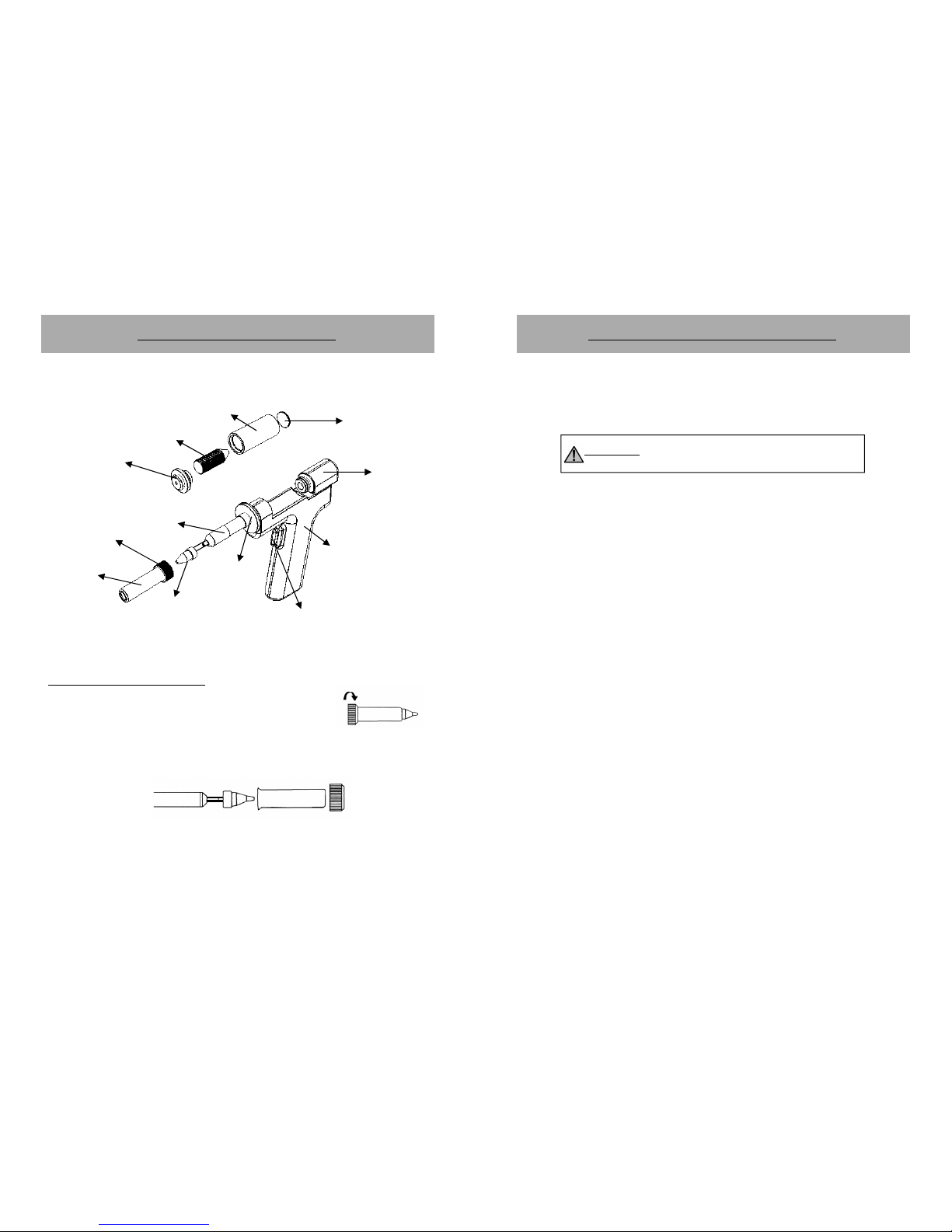
Soldering Iron Tip
Always keep the solder-plated section of the tip nozzle coated with a small amount
of solder. Oxide coating on the tip of the nozzle reduces its heat conductivity.
Coating the tip with a small amount of fresh solder ensures maximum heat
conductivity is obtained.
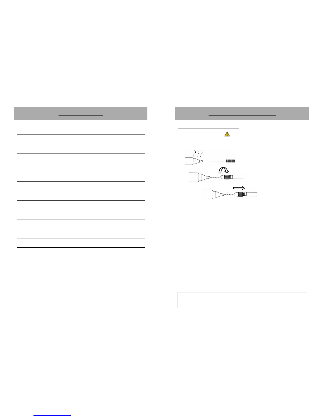
Replacing the Soldering Iron tip
1. Always turn OFF main power switch when removing or inserting a tip.
2. If the tip is hot, use the heat resistant pad to pull it out.
3. Insert the new tip fully into the handle. If the tip is not fully inserted (or if the
tip is damaged), the device will display “PLUG”. Indicating a problem with the
contacts of the soldering iron or the tip.
Soldering Iron Error Messages
1. Soldering Iron connection assembly is not connected or not properly connected
to the receptacle on the control panel.
2. Soldering iron sensor, cord or connection is damaged and needs to be
replaced. The device will display “PEn”. Indicating a problem with the contacts
between the soldering iron and the main unit.
3. Soldering iron heating element has reached the end of its life, the temperature
would consistently display a low temperature value followed by “Err” display.
Indicting a problem with the heating element or a reversed sensor polarity.
9
9
IMPORTANT REMINDERS:
1. Make sure the equipment is placed on a flat stable surface and all
the heat-generating components placed on their respective
holders or stands.
2. Ensure all terminal connections are properly secured.
IMPORTANT: Please refer to the
CONTROL ANEL GUIDE
page for buttons and
display panel directory.
OPERATING GUIDELINES
A. INITIAL PROCEDURES
1. Plug the device to the main power source using the power cord provided
in the package.
2. Switch ON the device by activating the main power switch.
3. The display panels, will display show “OFF”. The system will remain at
this state until the user activates a function.
B. SOLDERING IRON
1. Connect the Soldering Iron connection assembly to the 7-pin receptacle
located at the front of the control panel (“9” from the CONTROL PANEL
GUIDE).
2. Follow the initial procedures (“A. INITIAL PROCEDURES”).
3. Connect the vacuum tube to the Smoke Absorber Terminal or Vacuum
Cap (“7” from the control panel). If smoke absorber function is to be
used.
4. To activate the “SOLDER IRON” function, press and hold the soldering
iron function button for 3 to 5 seconds (“3” from control panel). The
soldering iron temperature display will momentarily show the current set
temperature then switch to displaying the actual temperature.
5. Adjust the soldering iron temperature using the SOLDERING IRON
TEMPERATURE ADJUSTMENT buttons (“5” from the control panel).
6. To activate the smoke absorber function, simultaneously press both up
and down button of the soldering iron temperature adjustment button
(“5” from the control panel).