aoyue INT 738H User manual

INSTRUCTION MANUAL
Thank you for purchasing Aoyue Int738H Multi-Function
Re-Working System.
It is important to read the manual before using the equipment.
Please keep manual in accessible place for future reference.
INT 738H
(Centigrade / Fahrenheit switchable)
Multi-Function
Re-Working System
AOYUE
®

2
TABLE OF CONTENTS
Product Description ………………………………………… 3
Specifications ………………………………………………… 3
Package Inclusion …………………………………………… 4
Functions and Features …………………………………. 5
Safety Precautions ………………………………………… 6
Assembly and Preparation ……………………………… 7
Control Panel Guide ……………………………………….. 8
Operating Guidelines ………………………………...…… 9—11
Auto-Sleep Functions …………………………………..… 12—13
Digital Calibration ……………………………………..…… 14—15
Centigrade/Fahrenheit switching…………………………. 16
Care and Maintenance …………………………………… 17
Basic Troubleshooting Guide …………………..……… 18—19
Air Nozzles ……………………………………………….…… 20
This manual is designed to familiarize and instruct the
operator with the proper usage and maintenance of the
equipment. The “Care and Safety Precautions” section
explains the hazards of using any type of soldering or
reworking device. Please read carefully and observe the
guidelines in order to maximize usage and minimize the
risk of injury or accidents .
Manufacturer:
AOYUE INTERNATIONAL LIMITED
Jishui Industrial Zone, Nantou, Zhongshan City,
Guangdong Province, P.R.China
http://www.aoyue.co

3
The Aoyue INT738H Lead-Free Repairing System is a reworking
equipment that combines the functionality of Hot Air Gun, 70 watts
Soldering Iron and Smoke Absorber in one package.
It has several safety features such as the auto-cooling process of
the Hot Air Gun. This functionality protects the device (and its
components) from excessive heat upon reaching any of the following
conditions: (1) when the soldering gun remained idle on its resting
handle after a certain period and (2) when the temperature of the
device is above a safe threshold upon turning off. It has several
advanced features such as solder iron digital calibration, configurable
auto sleep for hot-air and soldering iron and switchable centigrade or
Fahrenheit readout.
PRODUCT DESCRIPTION
MAIN STATION
Power Input : available in 110V / 220V
Station Dimensions: 188(w) x 126(h) x 250(d) mm
Weight: 5.6Kg
SOLDERING IRON
Power Consumption: 70W
Temperature Range: 200°C - 480°C
Heating Element: Ceramic Heater
Output Voltage: 24V
HOT AIR GUN
Power Consumption: 500W
Temperature Range: 100°C - 480°C
Heating Element Metal Heating Core
Pump/Motor Type: Diaphragm Pump
Air Capacity: 23 l /min (max)
SPECIFICATION
Specifications are subject to change without prior notice.

4
PACCKAGE INCLUSIONS
* Type of soldering tip included might change depending on availability.
** Kindly refer to soldering iron stand installation on page 7 for parts and
instructions.
1 unit Int 738H Main Station with Hot Air Gun and Holder
1 pack AT-7 Hot Air Nozzle Set(1124,1130.1197,1010,1313,1919 ,936
Sponge, Suction nozzle cover)
1 pc 20094 Spare Hot Air Gun Heating Element
1 pc T005 Soldering Tweezers
1 pc Tip Alignment Tool
1 pc B018 Solder Iron with Smoke Absorbing function
1 pack Soldering Iron Tips(9pcs) includes (T-B, T-LB, T-0.8D, T-1.2D,
T-1.6D, T-2.4D, T-1C, T-0.8C, T-0.5C)
1 pc C031 Heating Element
1 pc 2680 Soldering Iron Stand
1 pc Large Copper Ball
1 pc 932-3 Handle Vacuum Pick-up
1 pc G001 IC Popper
1 pc H036 Soldering Paste
1 pc Tool Box
1 pc M4 Nut
1 pc Instruction Manual
1 pc Power Cord

5
FUNCTION and FEATURES
●Microprocessor-controlled ESD safe equipment.
●3-in-1 repairing system combining Hot Air Gun, Soldering Iron, and
Smoke Absorber in one sophisticated package.
●Digital control and display of hot air temperature, soldering iron
temperature, and air pressure with touch type panel controls for
precision and ease of use.
●Switchable temperature readout between Fahrenheit and
Centigrade.
●Integrated smoke absorber functionality with filter pad to
efficiently absorb and filter harmful fumes.
●User configurable 1 to 30 minute idle-to-auto-stand-by mode (with
5 minutes as default) for additional device protection and power
saving.
●Built-in auto-cooling process that protects the system and its
components from excessive heat, prolonging usage life.
●Built-in auto-sleep mode for soldering iron and desoldering gun.
●Compatibility with air nozzles of various types.
●Compatibility with different kind of soldering tips.

6
SAFETY PRECAUTIONS
CAUTION: Improper usage can cause serious injury to personnel
and/or damage to equipment. For your own safety, please observe
the ff. precautions.
●Check each component after opening the package to make sure
everything is in good condition. If there are any suspected damage,
do not use the item and report the issue to your vendor.
●Turn OFF the
Main Power Switch
and unplug the device when
moving the device from one location to another.
●Do not strike or subject the main unit to physical shock. Use
carefully to avoid injury and damage to any part.
●Handle with care.
- Never drop or sharply jolt the unit.
- Contains delicate parts that may break if the unit is dropped.
●Make sure the equipment is always grounded. Always connect
power to a grounded receptacle.
●Temperature may reach as high as 480°C when switched ON.
- Do not use the device near flammable gases, paper and other
flammable materials.
- Do not touch heated parts, which can cause severe burns.
- Do not touch metallic parts near the tip.
●Disconnect the plug from the power source if the unit will not be
used for a long period.
- Turn OFF power during breaks, if possible.
●Use only genuine replacement parts.
- Turn OFF power and let the unit cool before replacing parts.
●The unit may produce a small amount of smoke and unusual odor
during initial usage. This is normal and should not yield any
negative result when reworking.
●Soldering process produces smoke — use on well ventilated place.
●Do not alter the unit, specifically the internal circuitry, in any
manner.

7
ASSEMBLY and PREPARATIONS
A. Main Station
As soon as the equipment has been removed from the package,
REMOVE THE SCREW located at the center of the bottom of the
main unit. This screw holds the pump in place during transportation.
B. Soldering Iron Stand
C. Soldering Iron
1. Connect the soldering iron cord assembly to the soldering iron
output terminal found at the lower middle portion of the main unit.
2. Place the soldering iron to the soldering iron stand.
D. Smoke Absorber
1. Attach the smoke absorbing tube to the suction vacuum cap. Make
sure the cord connections are free from tangles.
F. Hot Air Gun
The Hot Air Gun holder was installed on the station upside down for
packaging purpose. To set up the Hot Air Gun holder:
1. Loosen the two screws that secure the holder to the station.
2. Turn the holder right side up.
3. Re-fasten the two screws.
4. Place the hot air gun onto the holder in preparation for usage.
WARNING: Failure to remove the screw before using the
equipment can cause damage to the system.
0
+

8
CONTROL PANEL GUIDE
LEGEND:
1 — Air Pressure Gauge
2 — Hot Air Gun Temperature Adjustment Buttons
3 — Air Pressure Adjustment Buttons
4 — Soldering Iron Temperature Adjustment Buttons
5 — Hot Air Gun Output Terminal
6 — Smoke Absorber Terminal or Vacuum Cap
7 — Soldering Iron Receptacle
8 — Main Power Switch
9 — Soldering Iron Function Switch
10 — Soldering Iron Temperature Display
11 — Smoke Absorber Function Switch
12 — Air Pressure Display
13 — Hot Air Gun Temperature Display
14 — Hot Air Gun Function Switch
1
2
3
4
8
9
10
11
12
13
14
Prefixes
and
meanings:
“H” - actual temperature
“” - temperature being set
“C” - cooling down
“---” - sleep mode display
“OFF” - function deactivated display
Prefixes and
meanings:
“H” - actual temperature
“” - temperature being set
5 6 7

9
IMPORTANT REMINDERS:
1. Make sure the equipment is placed on a flat stable surface
and all the heat-generating components are placed on their
respective holders or stands.
2. Ensure all function switches are OFF prior to reworking.
3. Ensure all terminal connections are properly secured.
IMPORTANT: Please refer to the CONTROL PANEL GUIDE
page for buttons and display panel directory.
OPERATING GUIDELINES
A. INITIAL PROCEDURES
1. Plug the device to the main power source using the power cord
provided in the package.
2. With all function switches deactivated and all terminal connections
properly secured, switch ON the device using the
Main Power Switch
(“8” from the control panel).
3. The display panels, “10” and “12” will temporarily show the product
name in a scrolling manner and then display “OFF”on all rows once
the scroll is finished. The system will remain in this state until the user
activates a function.
B. HOT AIR GUN
1. Follow the initial procedures above, “A. INITIAL PROCEDURES”.
2. Activate
Hot Air Gun Function Switch
(“14” from the control panel).
3. The system will immediately start to blow air at an airflow rate of 50
while rapidly and safely increasing the air temperature to 100°C
(default system operating parameters). These values will be reflected
on the Hot Air Gun Air Temperature and Air Pressure display panels,
“13” and “12” from the control panel, respectively. The metal ball
inside the air pressure gauge (“1” from the control panel) will also
settle somewhere in the middle of the visible area indicating that the
system is blowing air at an average or normal rate.

10
OPERATING GUIDELINES
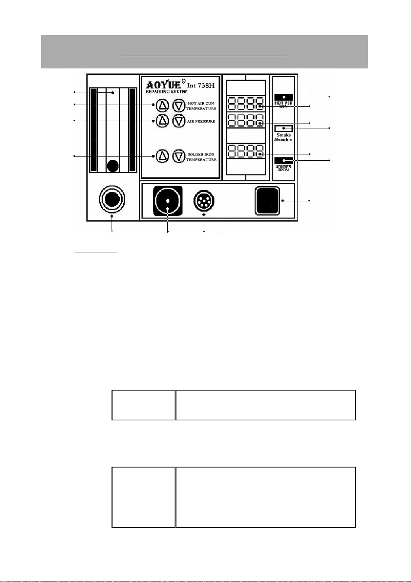
4. Adjust the air pressure level using the
Air Pressure Adjustment Buttons
(“3” from the control panel).
5. Adjust the hot air gun air temperature using the
Hot Air Gun
Temperature Adjustment Buttons
(“2” from the control panel). The
prefix of the display for Hot Air Gun Temperature will change from
“H” to “” indicating that temperature is being adjusted. It will return
to “H” (indicating actual temperature) while the temperature is
gradually increasing or decreasing until the set temperature is
reached.
6. Reworking task can be started 1 minute after the desired hot air
temperature and airflow level are reached, indicated on display
panels “10” and “12”, respectively.
7. When reworking is complete, return the Hot Air Gun to its holder
and DO NOT immediately turn OFF the
Main Power Switch
.
8. Turn OFF the
Hot Air Gun Function Switch
first in order to activate
the auto-cooling process. The system will start to blow air (at room
temperature) at a fast rate to reduce heat from the hot air gun and
bring down the temperature to a reasonable safe level of 90°C.
During this time, the prefix of the display for hot air gun
temperature will also change from “H” to “C” while temperature is
gradually decreasing. Likewise, the air pressure level is at its highest
reading as indicated from the display panel. Once the temperature
drops to approximately 90°C the system will halt and display “OFF”
on the panel. It is now safe to switch OFF the
Main Power Switch
.
9. Turn OFF the
Main Power Switch
.
10. Unplug the device from the main power source.
IMPORTANT: When adjusting the hot air gun temperature, it is
strongly advised to initially increase the airflow level in order to
manage the system temperature. This is to protect the heating
element inside the handle from excessive heat and avoid the pos-
sibility of subjecting adjacent components to thermal shock.

11
OPERATING GUIDELINES
NOTES:
1. Hot Air Gun Temperature is adjustable between 100°
and 480°C with an increment of 2° on each step.
2. Hot Air Gun Airflow Rate is adjustable between 10
and 100 with an increment of 2 on each step.
C. SOLDERING IRON
1. Connect the Soldering Iron connection assembly to the 6-pin
Soldering Iron Receptacle
located at the front of the control panel
(“7” from the control panel).
2. Follow the initial procedures (“A. INITIAL PROCEDURES”).
3. Connect the vacuum tube to the
Smoke Absorber Terminal
or
Vacuum Cap
(“6” from the control panel). If smoke absorber
function is to be used.
4. Activate the
Soldering Iron Function Switch
(“9” from control panel).
This will automatically start to increase the temperature of the
soldering iron to 350°C (default).
5. Adjust the soldering iron temperature using the
Soldering Iron
Temperature Adjustment Buttons
(“4” from the control panel).
6. If smoke absorber function is to be used. Activate the
Smoke
Absorber Function Switch
(“11” from the control panel).
7. Start using the soldering iron as soon as desired temperature is
reached.
8. When the task is finished, deactivate the
Smoke Absorber Function
Switch
.
9. Deactivate the
Soldering Iron Function Switch
.
10. Allow sufficient time for the soldering iron to cool down before
keeping in a safe storage.

12
AUTO SLEEP FUNCTIONS
A. Auto-Sleep Mode (Hot Air Gun)
The device has a built-in auto-sleep mode feature such that if the
Hot Air Gun sits on its handle and remained idle after a certain period
(the prefix of the display for Hot Air Gun air temperature will also
change from “H” to “L”) , the device will switch to sleep mode. This
mechanism is triggered by a countdown timer so when the time has
elapsed, the system will blow air (at room temperature) at maximum
rate in order to bring down the temperature. During this time, the prefix
of the display for Hot Air Gun air temperature will also change from “L”
to “C”. Once the temperature drops to approximately 90°C, the Hot Air
Gun will automatically stop and show an all-dash “- - - -”display
indicating that the system is now on sleep mode.
B. Changing SLEEP Mode Timer (HOT AIR GUN)
By default, the system has 5-minute countdown time before the
hot air gun goes to sleep mode. This can be altered by the following
procedure.
1. While the hot air gun is on stand-by mode (“OFF” is displayed
on the panels “13” and “12”), hold both UP and DOWN
buttons of the
Hot Air Gun Temperature Adjustment Buttons
.
2. Wait until “t005” is displayed on the Hot Air Gun Temperature
display panel, “13”.
3. Release the buttons when “t005” appears.
4. Adjust the time using the same UP and DOWN buttons of the
Hot Air Gun Temperature Adjustment Buttons
.
5. Confirm the change by activating the
Hot Air Gun Function
Switch
.
6. The system will immediately switch back to operation and use
the defined countdown parameter for the entire usage.

13
AUTO SLEEP FUNCTIONS
NOTES:
●The sleep mode timer is configurable between 1and 30 minutes.
●Sleep mode settings for Hot-Air Gun and Soldering Iron is saved
into the memory an shall remain effective until it is reset or new
data is entered.
C. Activating Soldering Iron Auto-Sleep Mode
The Soldering Iron’s SLEEP mode is deactivated by default. Follow
the set of procedures below to activate this feature.
CONDITION: SOLDERING IRON function is inactive.
1. While soldering iron is displaying “OFF”or in stand-by mode, push
both UP and DOWN buttons of the
Soldering Iron Temperature
Adjustment Buttons
(“4” from the CONTROL PANEL GUIDE page).
2. Wait until “t0FF” appears from soldering iron temperature display
panel. This means sleep mode is currently turned OFF.
3. Release the two buttons after the change in display.
4. Use the same two buttons to adjust the countdown time. “t001”
means solder iron will go to sleep in 1 minute. Timer is adjustable
from 1 to 60minutes.
5. Confirm the change by activating the SOLDERING IRON switch.
6. To DEACTIVATE this feature, simply follow the above procedures.
This time, select “tOFF” .
7. During sleep mode, the soldering iron temperature display panel
will show an all-dash, “- - - - ” .
8. To wake the soldering iron from sleep mode, press the soldering
iron temperature adjustment buttons.

14
Utilizing the Solder Iron Digital Temperature Calibration
By default, the system is properly calibrated but for cases when a
little adjustment of the soldering iron calibration is required the following
procedure can be done.
1. Turn ON the
Soldering Iron Function Switch
.
2. Set to appropriate temperature you want to calibrate. Place the
tip of the soldering iron on an external temperature sensor.
3. The readings on the external temperature sensor should be
more or less equal to the displayed temperature.
4. If there are large discrepancy in the temperature reading we
can re-calibrate the temperature setting.
5. While the solder iron is operating make sure the hot air gun is in
OFF mode (“0FF” is displayed on the panels “6” and “7”), hold
the air pressure UP button for a few seconds until four zeroes
are displayed “0000” .
6. Adjust the temperature compensation using the UP and DOWN
buttons of the
Soldering Iron Temperature Adjustment Buttons
.
7. A zero “0” on the first digit signifies addition to the current
temperature and a minus “-” on the first digit will subtract the
displayed value from the current settings.
8. Confirm the change by pressing the air pressure down button.
DIGITAL CALIBRATION
Initial display when
in calibration mode
Increase tempera-
ture by 38 degrees
Decrease tempera-
ture by 30 degrees

15
DIGITAL CALIBRATION
Solder Iron Digital Temperature Calibration Example
●The external temperature sensor displays 248 to 252 degrees.
●The set temperature and displayed actual temperature of the
soldering iron is 300 degrees.
●300 — 248 = 52. An additional adjustment of 52 degrees is
required.
●Enter calibration mode
●We increase from “0000” to “0052”.
●Exit calibration mode.
●The external temperature sensor would now display 298 to 302
degrees.
NOTES:
●The calibrated data is saved into the memory an shall remain
effective until it is recalibrated again or new data is entered.
●Calibration will only make the newly calibrated point the most
accurate. Other temperature points may be a little off.
●The soldering Iron has a lowest temperature limit such that when
the temperature has been set to 200 degrees with external actual
temperature also showing 200 degrees, further decreasing the
temperature offset would be only have minimal effect to the
actual temperature.
●To reset the calibration settings to factory setting, switch
OFF and ON the unit and while holding the hot-air temperature
up button until the banner finishes scrolling, the Set
temperature / Temperature calibration of the unit would revert to
its default factory setting.

16
CENTIGRADE /FAHRENHEIT
Part No. Description
20094 Hot air gun heating element
30106S Plastic handle of hot air gun
S009 Hot air gun complete handle
20962 Hot air gun metal pipe
B012 Soldering Iron complete handle
Spare Parts Guide
To switch between the centigrade and Fahrenheit scale
By default, the system is set to the centigrade scale, if the
Fahrenheit scale is preferred proceed with the following
procedures .
1. Turn OFF power to the main unit.
2. Make sure all function switches are in the OFF position.
3. Press and hold the down button of the soldering iron
temperature adjustment button while switching the main POWER
switch to ON.
4. The initial display would show a scrolling “AOYUE” name and
“768F” the “F” at the end of the model number indicates that
current settings are in the Fahrenheit mode.
5. To switch back to using the Centigrade mode, Press and hold the
up button of the soldering iron temperature adjustment button
while switch the main switch ON.
6. The initial display would show a scrolling “AOYUE” name and
“768C” the “C” at the end of the model number indicates that
current system settings are in the Centigrade scale.

17
CARE and MAINTENANCE
Blower/Vacuum Air Terminal Filters
Filters should be cleaned and replaced regularly to avoid dirt which can
clog the air passage. More importantly, this will also effectively clean
the toxic fumes produced during soldering process.
Soldering Iron Tip
Always keep the solder-plated section of the tip/nozzle coated with a
small amount of solder. Oxide coating on the tip of the nozzle reduces
its heat conductivity. Coating the tip with a small amount of fresh solder
ensures maximum heat conductivity is obtained.
Replacing the heating element of the Hot Air Gun
The heating element is found in the middle part of the hot air gun.
The normal life of a heating element is 1 year under normal operating
conditions.
Steps:
1. Loosen the 3 screws that secure the handle.
2. Slide off the plastic tube.
3. Disconnect the ground wire sleeve.
4. Inside the pipe, the quartz glass and heat insulation are
installed. Loosen the cable and take out the heating element.
5. Insert new heating element and reconnect the terminal.
Be
careful not to rub Heating Element wire.
6. Reconnect the ground wire after replacing the element.
7. Assemble the handle again.
Soldering Iron Error Messages
1. Soldering Iron connection assembly is not connected
or not properly connected to the receptacle on the
control panel.
2. Soldering iron tip is damaged and needs to be
replaced. The device will display “PLUG”.
3. Indicating a problem with the contacts of the
soldering iron or the tip.

18
BASIC TROUBLESHOOTING GUIDE
PROBLEM 1: THE UNIT HAS NO POWER
1. Check if the unit is switched ON.
2. Check the fuse. Replace with the same type if fuse is blown.
3. Check the power cord and make sure there are no disconnections.
4. Verify that the unit is properly connected to the power source.
PROBLEM 2: HOT-AIR GUN TEMPERATURE DISPLAY IS ALWAYS
ABOVE 500oC
Description: Constant display of above 500oC temperature from the panel
then displays an “Err1” on the panel after a few minutes.
SOLUTION: The thermal sensor may be broken and needs to be replaced.
PROBLEM 3: HOT-AIR GUN ACTUAL AIR TEMPERATURE IS NOT
INCREASING
Description: Actual temperature reading is not increasing or decreasing based
on desired level.
SOLUTION: The heating element may be broken or is at the end of its life and
needs to be replaced.
PROBLEM 4: THE UNIT IS VIBRATING TOO MUCH
SOLUTION: Check if the 4 screws that hold the pump in place are properly and
tightly connected. Unplug the system from the main power source before
opening the case to check inside the station.
PROBLEM 5: THE UNIT IS VERY NOISY
SOLUTION: Make sure the screw at the center of the base of the main unit has
been removed. This holds the pump in place during transportation and needs to
be removed before using the equipment.
PROBLEM 6: SOLDERING IRON TEMPERATURE DISPLAY PANEL
SHOWS “PLUG” CHARACTERS
Case 1: The system shows “PLUG” from the soldering iron temperature
display panel .
SOLUTION 1: Check if the soldering iron connection assembly is properly
connected and secured to the receptacle on the control panel.
SOLUTION 2: Make sure the soldering iron tip is properly inserted and secured
inside the handle. Loose contacts between the tip and handle can also cause
this error message.
SOLUTION 3: See “Soldering Iron Error Messages” on page 21 for further
details.

19
BASIC TROUBLESHOOTING GUIDE
PROBLEM 7: AIR PRESSURE LEVEL IS SIGNIFICANTLY LOW NO
MATTER HOW HIGH THE AIRFLOW LEVEL IS CALIBRATED
Case 1: Check the mains voltage (AC power source). If the voltage level falls
significantly low, about 15-20% lower than the standard, there will also be a
noticeable drop in the air pressure level.
SOLUTION: Please refer to your local power service provider.
Case 2: The microcontroller might have detected the operating frequency
incorrectly. The user will notice that airflow level is weaker with reference to the
airflow gauge compared with the displayed value.
SOLUTION: Turn off the unit and on again to let the device re-detect the
proper operating frequency.
Case 3: The Suction Vacuum cap is connected to the Smoke Absorber
Terminal or Vacuum cap instead of the Wire mesh cap.
SOLUTION: Change the cap to the Wire mesh cap. This allows more air to
pass through the system. Make sure as well that the vacuum tube of the
soldering iron or desoldering gun is not connected.
Case 4: The Wire mesh cap is connected but airflow level is still low.
SOLUTION: Check the filter pad inside for dirt that can block the air passage.
Clean or replace if necessary.
ADDITIONAL SOLUTION: Check for any tangles in the tube of the hot air
gun that can cause the air blockage.
PROBLEM 8: UNIT SHOWS UNCONVENTIONAL BEHAVIOR
Description: Unit operates erratically.
SOLUTION1: Try to switch OFF the device and switch ON again. Unplug the
system from the main power source and plug in again when necessary
SOLUTION2: Restore unit to default factory setting. switch OFF/ON the unit
while holding the hot-air temperature down button until the banner finishes
scrolling, the unit would revert to its default factory setting.
OTHER PROBLEMS NOT MENTIONED:
Contact the vendor.

Replacement Air
Nozzles
2Ø
1325 Air Nozzle
1142 Air Nozzle
MODEL#NOZZLE SIZE Ø
1124 2.4mm
1130 4.4mm
1194 6mm
1195 8mm
1196 7mm
1197 9mm
1198 12mm
MODEL#IC SIZE L(mm)
1191 SIP25L 26
1192 SIP50L 52.5
MODEL#IC SIZE L(mm) W(mm)
1010 9×9mm 10 10
1313 12×12mm 13 13
1616 15×15mm 16 16
1919 18×18mm 19 19
2828N 27×27mm 28 28
3030N 29×29mm 30 30
3232W 31×31mm 32 32
3636W 36×36mm 36 36
3939W 38×38mm 39 39
4141W 40×40mm 41 41
4343W 42×42mm 43 43
4545W 44×44mm 45 45
MODEL#IC SIZE A(mm) B(mm) C(mm) D(mm)
1125 10×10mm 9 9 16 16
1126 14×14mm 14 14 21 21
1127 17.5×17.5mm 18 18 25 25
1128 14×20mm 20 14 21 27
1129 28×28mm 28 28 35 35
1215 42.5×42.5mm 41 41 48 48
1261 20×20mm 19 19 26 26
1262 12×12mm 11 11 18 18
1263 28×40mm 38 28 35 45
1264 40×40mm 39 39 46 46
1265 32×32mm 31 31 38 38
MODEL#IC SIZE L(mm) W(mm) A(mm) B(mm)
1131 4.4×10mm 11 3.8 9 10.3
1132 5.6×13mm 16 4.7 14 11.7
1133 7.5×15mm 17 6 15 13
1134 7.5×18mm 20 6 18 13
1257 11×21mm 22 11 20 18
1258 7.6×12.7mm 12 7 10 14
1259 13×28mm 30 12.5 28 19.5
1260 8.6×18mm 20 7.7 18 14.7
MODEL#IC SIZE L(mm) W(mm) A(mm) B(mm)
1183 15×8mm 17 7 15 14
1184 18×8mm 20 9 18 16
1214 10×26mm 27 11 25 18
TSOL
SERIES
MODEL#IC SIZE L(mm) W(mm) A(mm) B(mm)
1185 13×10mm 11 11 9 18
1186 18×10mm 12 17 10 24
1187 18.5×8mm 11 18 9 25
MODEL#IC SIZE L(mm) W(mm) A(mm) B(mm)
1180 17×17mm 17.2 17.2 24.2 24.2
1181 19×19mm 18.2 18.2 25.2 25.2
1182 24×24mm 23.2 23.2 30.2 30.2
1203 35×35mm 34.2 34.2 41.2 41.2
BQFP
SE-
SGL SERIES
SIL SERIES
45º
10mm
5mm
22mm
22mm
22mm
22mm
22mm
22mm
22mm
SOJ
SERIES
SOP
SERIES
BGA
SERIES
QFP
SERIES
PLCC
SERIES
Ø
MODEL#IC SIZE A(mm) B(mm) C(mm) D(mm)
1135 17.5×17.5mm 17.5 17.5 24.5 24.5
1136 20×20mm 20 20 27 27
1137 25×25mm 25 25 32 32
1138 30×30mm 30 30 37 37
1139 7.3×12.5mm 7.5 12.5 14.5 19.5
1140 11.5×11.5mm 12 12 19 19
1141 11.5×14mm 12 14 19 21
1188 9×9mm 10 10 17 17
1189 34×34mm 35.5 35.5 42.5 42.5
Table of contents
Other aoyue Soldering Gun manuals