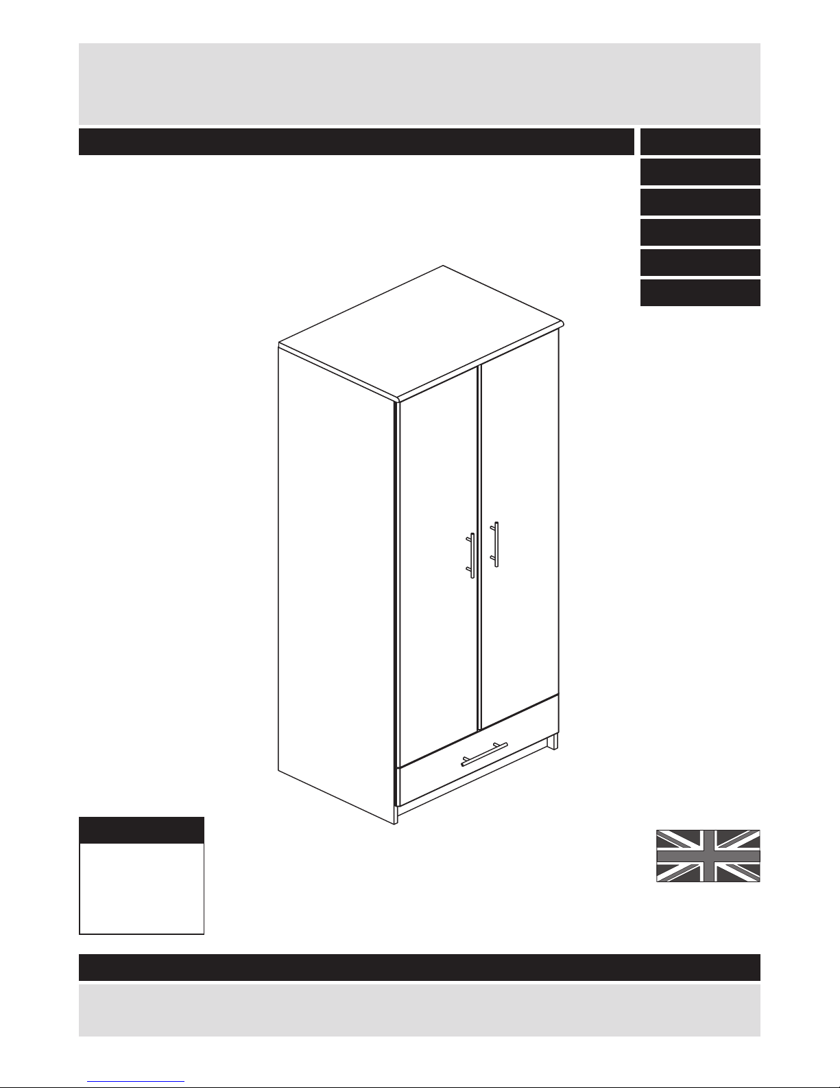
Argos 246/6848 User manual
Other Argos Indoor Furnishing manuals

Argos
Argos Tolga 346/0111 User manual

Argos
Argos Hallingford 305/2763 User manual

Argos
Argos 833/4792 User manual

Argos
Argos 244/9315 User manual

Argos
Argos 875/0383 User manual

Argos
Argos KINGSTON 6029731 User manual

Argos
Argos Amersham 724/4199 User manual

Argos
Argos 239/2352 User manual

Argos
Argos Caspian 365/6499 User manual

Argos
Argos Bali KD Armchair and Cushion User manual

Argos
Argos 903/6240 User manual

Argos
Argos White Toddler bed 4277891 User manual

Argos
Argos PENTON User manual

Argos
Argos 184/9198 User manual

Argos
Argos Victoriana 244/5034 User manual

Argos
Argos Stirling User manual

Argos
Argos Washington 425/8425 User manual

Argos
Argos Lamberto Ottoman TV Bed User manual

Argos
Argos Sywell 643/8047 User manual

Argos
Argos Ellie 244/7472 User manual


Popular Indoor Furnishing manuals by other brands


Coaster
Coaster 4799N Assembly instructions

Stor-It-All
Stor-It-All WS39MP Assembly/installation instructions

Lexicon
Lexicon 194840161868 Assembly instruction

Next
Next AMELIA NEW 462947 Assembly instructions

impekk
impekk Manual II Assembly And Instructions

Elements
Elements Ember Nightstand CEB700NSE Assembly instructions