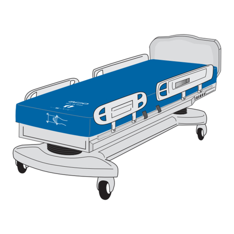
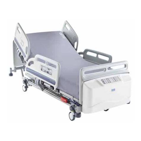
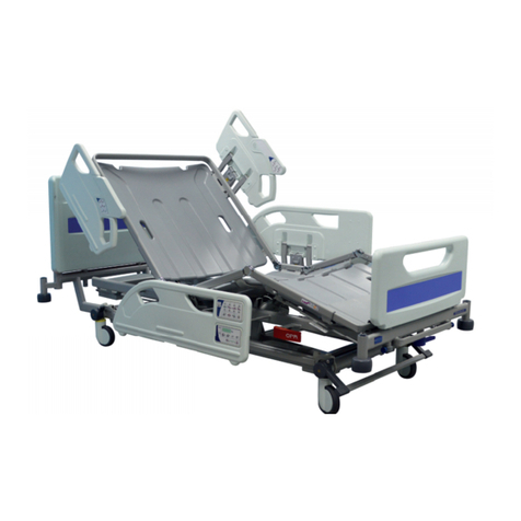
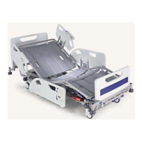
Arjo Prioma Series User manual

CTK-SM-REV8-060720
Service Manual
Prioma Medical Bed

Page | 1
Commercial in confidence. User Manual Revision CTK-SM-REV8-060720
WARNING: Indicates possible hazard in procedures or conditions which, if not
correctly followed, could result in death, injury or other serious adverse reactions.
Caution: Indicates possible hazard in procedures or conditions which, if not
correctly followed, could result in equipment damage or failure.
Explains or amplifies a procedure or condition
Indicates an optional item or feature
PREFACE
Read and understand this manual before attempting to service or repair the equipment.
This manual is intended for use by Arjo approved service technicians. The manual may be
provided to a customer in response to customer requirements, but in no event will Arjo be
responsible for any service or repair performed by customer.
Warnings, Cautions and Notes
General Warnings
•Before starting any service or maintenance procedures, ensure that the equipment
has been adequately decontaminated.
•Electrical equipment can be hazardous if misused. Obey all safety instructions. Do
not use electrically powered beds in the presence of flammable gases, such as
anaesthetic agents.
•The bed and its sub-assemblies are very heavy and appropriate precautions must be
taken to avoid injury when moving or lifting them.
•Disconnect the bed from the mains supply before starting any maintenance activity.
The bed will still operate on battery power unless the function is locked on the
Attendant Control or the Side Control panel.
•Do not remove protective covers or open electrical enclosures while the bed is
connected to the mains power supply.

Page | 2
Commercial in confidence. User Manual Revision CTK-SM-REV8-060720
CONTENTS
1.
Introduction …………………………………………………………………….............
4
1.1
About this manual …………………………………………….........................
4
1.2
Product Description …………………………………………….......................
5
2.
Decontamination ………………………………………………………………............
7
2.1
Cleaning ………………………………………………………………………….
7
2.2
Disinfecting ………………………………………………………………………
7
3.
Preventative Maintenance …………………………………………………...............
8
3.1
General …………………………………………………………………………..
8
3.2
Castors & Brakes ……………………………………………………………….
8
3.3
Battery Test ………………………………………………………………….......
9
3.4
Handset Checks (if fitted) ……………………………………………………...
10
4.
Testing ……………………………………………………………………………..........
11
4.1
Preliminary ……………………………………………………………………….
11
4.2
Electrical Functions ……………………………………………………………..
11
4.3
Manual Functions ……………………………………………………………….
12
5.
Troubleshooting ………………………………………………………………….........
13
5.1
Fault finding …………………………………………………………………......
13
5.2
Fault indications ……………………………………………………………......
14
5.3
Calibration ………………………………………………………………………
14
6.
Servicing Instructions …………………………………………………………..........
15
6.1
General …………………………………………………………………………..
15
6.2
Tools & Equipment ……………………………………………………………..
17
6.3
Electrical Assembly ……………………………………………………………..
18
6.4
Electrical Assembly Parts List ………………………………………………....
19
6.5
Undercarriage Assembly ……………………………………………………….
20
6.6
Crank & Crank Stabiliser Assemblies ……………………………………......
21
6.7
Base Frame/Mattress Platform Assembly ………………………………......
22
6.8
Backrest & Backrest Retraction Assemblies ……………………………......
23
6.9
Thigh & Foot Section Assemblies …………………………………………….
24
6.10
Base Extension & Linen Rack Assembly …………………………………….
25
6.11
Fold Down Tubular ¾ Rail Assembly …………………………………………
26
6.12
Split Side Rails –Head End …………………………………………………...
27
6.13
Split Side Rails –Foot End Short ……………………………………………..
28
6.14
Split Side Rails –Foot End Long ……………………………………………..
29
6.15
Brake / Steer Pedal Replacement …………………………………………….
30
6.16
Castors Replacement ……………………………………………………….....
30
6.17
Battery Backup replacement …………………………………………………..
31
6.18
Mains Power Cable replacement ……………………………………………..
32
6.19
Control Box replacement ………………………………………………………
33
6.20
Junction Box / Underbed Light replacement ……………………………......
34
6.21
Roving Handset replacement ………………………………………………....
35
6.22
Attendant Control OpenBus Mini Panel (ACP) replacement ………………
35
6.23
Attendant Control Panel (ACOM) replacement …………………………......
36

Page | 3
Commercial in confidence. User Manual Revision CTK-SM-REV8-060720
CONTENTS - Continued
6.24
Height Actuator replacement ……………………………………………….....
36
6.25
Thigh Panel Actuator replacement ……………………………………….......
37
6.26
Backrest Actuator replacement …………………………………………….....
37
6.27
Actuator Cables replacement ………………………………………………....
38
6.28
CPR Handle & Cable adjustment & replacement ...…………………….......
39
6.29
Backrest Damper replacement …………………………………………….....
39
6.30
X-Ray Backrest Damper replacement …………………………………….....
40
6.31
Linen Rack (Stripper) replacement …………………………….....................
40
6.32
Base Extension replacement ……………………………………………….....
40
6.33
Head-end Split Side Rail replacement …………………………………….....
41
6.34
Foot-end Split Side Rail replacement …………………………….................
41
6.35
Fold-down tubular Side Rails replacement ……………………………….....
42
6.36
Roller Buffer & Socket Adaptor replacement ……………………….............
42
6.37
Calf section Ratchet replacement ………………………………………….....
42
6.38
Stabiliser Arm replacement …………………………………………………....
43
6.39
Crank roller bearings replacement ……………………………………….......
43
6.40
Mattress Platform ABS Covers replacement ……………………….............
44
6.41
Mattress Retainer replacement …………………………………………….....
44
6.42
Powder coat restoration …………………………………………………….....
45
7.
Technical Data ………………………………………………………………................
46
7.1
Product Specifications ..………………………………………………………..
46
7.2
Environmental Protection ……………………………………………………...
47
7.3
Symbols & Labels ……………………………………………………………....
47
7.4
Product Lifetime ........................……………………………………………....
48
7.5
End of Life Disposal …..................…………………………………………....
48
7.6
Safe Disposal of Gas Springs ………...……………………………………....
48
7.7
Electromagnetic compatibility ………………………………………………....
49
8.
Transportation & Storage .........………………………………………………….......
50
9.
Regulatory Information .......…………………………………………………….........
51

Page | 4
Commercial in confidence. User Manual Revision CTK-SM-REV8-060720
1. INTRODUCTION
1.1 About This Manual
This manual contains information on the servicing and maintenance of the Arjo Prioma
Medical Bed.
Section 1.
Introduction (this chapter): General description of the equipment with an explanation of the
various features available, together with contact details for Arjo around the world.
Section 2.
Decontamination: recommended procedures for cleaning and disinfecting the equipment.
Section 3.
Preventative Maintenance: Details of regular, periodic maintenance actions to ensure
correct operation of the equipment.
Section 4.
Testing: Serviceability test to verify correct operation of the equipment if function is suspect
or following any maintenance or servicing procedure.
Section 5.
Troubleshooting: Fault symptoms, possible causes and suggested remedial actions.
Section 6.
Servicing Instructions: Procedures for removal and installation of replaceable parts and
sub-assemblies.
Section 7.
Technical Data: List of electrical and dimensional data for the equipment and components.
Instructions for safe disposal of gas springs.
Electromagnetic Compatibility (EMC) test results
Section 8.
Transportation & Storage: Information relating to transportation and storage temperatures
and conditions. Charging of batteries when beds are stored for prolonged periods of time.
Section 9.
Regulatory Information: Contact details.

Page | 5
Commercial in confidence. User Manual Revision CTK-SM-REV8-060720
1. INTRODUCTION - Continued
1.2 Product Description
The Arjo Prioma Medical Bed is an electrically operated acute care medical bed. The bed
has multiple functions to provide bed nursing positions for both patient and carer.
Scope
This service manual covers all Arjo Prioma Medical Bed variants.
Standard Features
oFour sectioned electrically operated profiling mattress platform with independent
adjustment of backrest angle, thigh section angle and calf section angle.
oSimultaneous adjustment of backrest and thigh sections by pressing one button (Auto
Contour).
oElectrically operated height adjustment.
oElectrically operated Trendelenburg and reverse Trendelenburg tilt.
oAuto (chair) seated function.
oSplit drop down side rails with integrated controls.
oRemovable mattress platform top covers.
o125mm single wheel central locking castors.
oDrainage Bag rail.
Optional Features
o125 Kick-stop brake castors
o125 & 150mm twin wheel central locking castors
oAdditional head-end brake pedals
oBase Extension & Bed Stripper
oFold down ¾ length tubular rails
oSplit side rails without integrated controls
oUnderbed Light
oBattery Backup for all electrical functions
oNurse & Patient Handsets
oAttendant Control Panels (ACP or ACOM)

Page | 6
Commercial in confidence. User Manual Revision CTK-SM-REV8-060720
1. INTRODUCTION - Continued
Figure 1: Prioma Bed
All power operated functions are operated by push button controls. Each function has
separate up and down push buttons with the exception of electronic CPR and
Trendelenburg functions with are a single touch control.
Depending on the bed model, the patient can control the bed via a hand-held handset or
by integrated controls on the inside face of the head end split side rails. The patient’s
controls adjust backrest angle, leg elevation and bed height.
The care giver can control the bed via a nurse handset or integrated controls on the
outside face of the head end split sides. The nurse’s (outer) controls adjust backrest angle,
height, calf angle, auto contour (seated position), Trendelenburg & reverse Trendelenburg,
CPR position and includes a lockout function, hence operation by the patient is at the
discretion of the carer.
The bed is also available with attendant control panel (ACP or ACOM) incorporating
functions lockout.
The electrical actuators consist of a screw and nut assembly driven by a 24V d.c. motor
and gearbox. Power for the actuators is derived from an switch mode a.c. power supplied
control box located below the seat section of the bed mattress platform. The control box
also houses the control electronics with the battery backup pack adjacent to it.
When the thigh section is raised, the knee-break angle between the calf and thigh sections
can be changed manually. The default position is Fowler (calf section angled down) but
this can be changed to vascular (calf section horizontal) by lifting the calf section.

Page | 7
Commercial in confidence. User Manual Revision CTK-SM-REV8-060720
2. DECONTAMINATION
WARNING
•Disconnect the bed from the mains power supply before carrying out
cleaning procedures.
•Do not allow the mains plug or power supply cord to get wet when
cleaning the bed.
•Disconnect the bed from the mains power supply before carrying
out cleaning procedures.
•The following procedure also applies to the beds accessories
but does not include the mattress.
2.1 Cleaning
Clean all surfaces with a disposable cloth soaked in a neutral detergent and a comfortable
hot temperature for bare hands.
Mattress platform sheet tops and head/foot panels can be removed from the bed and
cleaned separately.
Start by cleaning the upper sections of the bed work along all horizontal surfaces. Work
methodically towards the lower sections of the bed and clean the castors last. Take extra
care to clean areas that may trap dust or dirt.
Wipe over with a new disposable cloth moistened with clean water and dry with disposable
paper towels. Allow the cleaned parts to dry before replacing the mattress.
2.2 Disinfecting
After cleaning the bed as described above, wipe all surfaces with sodium
Dichloroisocyanurate (NaDCC) at a concentration of 1,000 parts per million (0.1%) of
available chlorine.
In the case of pooling body fluids, e.g. blood, the concentration of NaDCC should be
increased to 10,000 parts per million (1%) of available chlorine.
CAUTION
•Do not use abrasive compounds or pads or phenol-based disinfectant
solutions.
•Do not use jet stream cleaning or wash tunnels.
•Take care not to remove lubricant from the actuator pistons.

Page | 8
Commercial in confidence. User Manual Revision CTK-SM-REV8-060720
3. PREVENTATIVE MAINTENANCE
This product has been designed to be virtually maintenance-free between service
intervals. The degree of periodic maintenance required will be determined by use and
condition.
The following preventative maintenance checks and procedures should be carried out
every 12 months.
All service and repair activities must only be carried out by properly qualified and trained
persons approved by Arjo.
Disposal of the product and its components should be compliant with local regulations.
WARNING
Before starting any maintenance activity, disconnect the bed from the mains
power supply. The bed sections will still operate on battery power unless the
function has been disabled on the side rails outer controls or ACP.
Avoid skin contact with lubricants. Gloves and protective clothing should be
worn when carrying out maintenance work.
3.1 General
Examine the bed for obvious signs of damage. Make sure that all visible fixings/fasteners
are secure and not missing.
Examine all flexible cables for cuts, abrasions, kinks or other deterioration.
Check the mains plug and cable for any signs of damage. If either the mains plug or cable
is damaged, both must be replaced as a complete assembly. Under no circumstances
should the integral moulded plug be replaced with a rewireable plug.
3.2 Castors and Brakes
Check the brakes for efficient operation.
Check that the steering lock operates effectively.
Poor braking or steering performance indicates that one or more castors require
replacement (the castors on this product are not adjustable).

Page | 9
Commercial in confidence. User Manual Revision CTK-SM-REV8-060720
3. PREVENTATIVE MAINTENANCE - (continued)
3.3 Battery Test
Check the condition of the backup battery by carrying out the following test.
1. Disconnect the bed from the mains electricity supply.
2. Raise the mattress platform to maximum height.
3. Raise the backrest and thigh sections to maximum elevation.
4. Press and hold the CPR button. The mattress platform will
flatten and lower to a mid-height position.
5. Lower the mattress platform to minimum height.
6. Apply maximum head down tilt (Trendelenburg).
7. Return the mattress platform to the level position, then
apply maximum foot down tilt (reverse Trendelenburg).
If this test is not completed successfully, connect the bed to mains electricity supply for at
least eight hours to recharge the battery, then perform the test again. If the bed fails a
second time, contact Arjo or an approved service agent.
To maintain best performance, the backup battery should be replaced every four years by
an approved service agent.
CAUTION
If the bed is stored for a long period of time, it should be connected to the
electricity supply for 24 hours every three months to fully recharge the backup
battery, otherwise it may become unserviceable.

Page | 10
Commercial in confidence. User Manual Revision CTK-SM-REV8-060720
3. PREVENTATIVE MAINTENANCE - (continued)
3.4 Handset Checks
Patient Handset:
Between each new patient, Arjo strongly advises that Preventative Maintenance checks
are conducted on the patient handset.
Nurse Handset:
Arjo strongly advises that the Nurse Handset is visually inspected for obvious damage
before each use if practicable. When using a specific function staff should be aware of and
be checking for any of the symptoms listed in point 3 below.
Preventative Maintenance Checks:
Arjo recommends that the full check and testing regime is conducted between each bed
use, or worst case during annual preventative maintenance. This should take no more than
one (1) minute to complete.
3.4.1 Visual Inspection of Handset Casing
•Inspect the outer plastic casing for any obvious cracks or damage.
•Inspect for damage to the front cover (outer label) particularly over the
buttons where the label may be torn or indented.
•If any damage is identified while conducting checks immediately lock out the
handset using the bed lockout function and report the damage to
maintenance staff or replace the handset.
3.4.2 Inspection of the cable and cable insulation
•Inspect the cable for any nicks or cuts in the insulation.
•Inspect for any evidence that the cable may have been squashed/flattened.
•Squashed or flattened cables may indicate a possible break in the internal
conductors or insulation causing conductors to short together, which could
cause unwanted movement of the bed. Any handsets found with obvious
damage to the cable insulation, immediately lock out the handset using the
lockout function and report the damage to maintenance staff or replace the
handset.
3.4.3 Tactile inspection of the buttons.
All buttons should be operated, and response tested.
Depress each button on the handset. Each button should have a positive audible click
that is also felt. The function being pressed should also operate.
If the button:
•Does not have a click feel
•Does not have an audible click sound
•Does not immediately operate the function
•Feels soft offering no resistance
•Feels different to the rest of the buttons
•Travels further when depressed
Immediately lock out the handset using the lockout function and report the damage to
maintenance staff or replace the handset. Quarantine the bed and contact an Arjo
approved Technician.

Page | 11
Commercial in confidence. User Manual Revision CTK-SM-REV8-060720
4. TESTING
The following serviceable tests should be performed before returning the bed to use after
service, or if the function is suspect.
These instructions should be read in conjunction with the instructions for use supplied with
the product.
If the result of any test is unsatisfactory, investigate and take the appropriate remedial
action. Refer to section 6 (Troubleshooting) and section 6 (Servicing Instructions).
All references to left and right are when viewed from the head-end (i.e. by a patient lying
on the bed and facing up)
WARNING
If any electrical assembly or wiring has been replaced or repaired, the
appropriate electrical safety checks must be made.
Keep clear of the bed when it is being operated. Severe injury can result from
crushing by moving parts.
4.1 Preliminary
Do the following preliminary checks before testing:
•Connect the bed to mains power supply. If necessary, reinstate all locked out
functions.
•Check that no furniture or other obstruction can impede the movements of the bed.
4.2 Electrical Functions
Bed Controls
1. Check that each ACP (if fitted) operates all bed functions over the full range of
movement as specified in section 7 (Technical Data). Verify that the actuators are
de-energised when the control button is released, or the limit of travel is reached.
2. Check that each of the patient control operating buttons all function correctly.
3. Check that each of the nurse control units operate the backrest, Tilt, height, thigh
section and Auto Contour (seated position) correctly.
4. Check that lockout functions on the nurse control and ACP (if fitted) disables the
appropriate functions on all the control units.
5. With the bed in a flat or foot-down tilt position, press and hold the Trendelenburg
control button on the nurse control or ACP (if fitted) and check that the bed tilts in
Trendelenburg (head-down tilt) position.
6. Raise the backrest, thigh section and bed mattress platform to maximum height.
Press and hold the CPR button and verify that the mattress platform returns to the
flat, mid height position.
7. Check that the underbed light is illuminated whenever the bed is connected to the
mains supply.

Page | 12
Commercial in confidence. User Manual Revision CTK-SM-REV8-060720
4. TESTING - Continued
Battery Operation.
Check operation of the battery by completing the steps described in section Battery
Test (refer to section 3)
4.3 Manual Functions
The following tests check functions that are not electrically powered.
Brakes & Steering.
Check the brakes for efficient operation. Apply the brakes by pressing down on either
one of the central locking brake levers and push the bed. None of the four braking
castors should rotate.
Place the pedals in the “steer” position and verify that the tracking (steering) castor is
engaged and does not swivel. The tracking castor should be placed at the head end,
and on the same side as the link bar.
Split Side Rails.
Check operation of each of the four split side rail sections. Verify that the release and
latching mechanism are effective and that the sides are securely locked when raised.
Also, check that sides drop down in a controlled manner when locking mechanism is
released.
Base Extension.
Check that the base extension extends and retracts smoothly and easily. Make sure
that release handle and catch bar operate easily and that the extension locks securely
in both extended and retracted positions.
Bed Stripper (linen Rack).
Check that the linen rack extends and retracts smoothly and easily.
Emergency CPR Release.
Use the bed controls to raise the backrest to about 45°. Operate either CPR release
lever to verify that the backrest quickly descends to a horizontal (flat) position in a
smooth, controlled manner. Check that both CPR release handles operate correctly.
Manual Calf Section.
Use the bed controls to fully raise the thigh section. Holding the Calf section by the
mattress keep handle (found on either side of the bed), slowly lift as the section will
incrementally click and lock into position if released. To lower the calf section back
down, lift the calf section all the way up and the ratchet system will release allowing the
calf section to be lowered down to the neutral position.

Page | 13
Commercial in confidence. User Manual Revision CTK-SM-REV8-060720
5. TROUBLE SHOOTING
5.1 Fault Finding
The following table identifies some fault symptoms, possible cause(s) and suggested
remedial action.
Symptom
Possible Cause
Remedial Action
All actuators inoperative
Functions locked on nurse
control panel or ACP.
Unlock functions
Power disconnected and
backup battery discharged.
Connect the power cable to
a suitable mains power
supply outlet
Fuse blown and backup
battery discharged.
Call Arjo Service
department
Roving handset, control
panel or ACP disconnected.
Check all cable connections
between control units,
junction box and control
box.
One actuator inoperative
Actuator cable
disconnected or faulty.
Check cable connection
into control box and
actuator. Check for faulty
cable.
Main lift actuators fail to
operate and an audible
beeping sound can be
heard when handset is
activated
Control Box requires
calibrating possibly due to
bed being operated on
backup power, when
batteries were fully
discharged.
Ensure bed is connected to
mains power supply and
carry out calibration
procedure.
Brake and/or steering lock
not effective
Worn or damaged castor(s)
or brake pedal
Replace castor or brake
pedal.
Backrest Emergency CPR
not effective
Release mechanism not
properly adjusted
Check and re-adjust

Page | 14
Commercial in confidence. User Manual Revision CTK-SM-REV8-060720
5. TROUBLE SHOOTING - (continued)
5.2 Fault Indications - Could be Flashing LEDs or Audible Warnings.
The bed’s control software can detect and indicate faults with the electrical system by
means of audible beeps and flashing LEDs.
Audible Warnings.
POSITION LOST on an actuator is indicated via an intermittent beep 200msec ON /
200msec off.
Try the RESET/CALIBRATION procedure and in turn run all functions. If problem persists,
locate faulty actuator or cable.
FATAL ERROR is indicated via an intermittent beep 50msec ON / 500msec OFF.
Try the RESET/CALIBRATION procedure and then in turn run all functions. If problem
persists, locate faulty actuator/cable and replace as required.
HOOT is indicated by a constant beep.
Try the RESET/CALIBRATION procedure and then in turn run all functions. If problem
persists, locate faulty actuator/cable and replace as required.
BATTERY LOW is indicated by a 50msec beep when a function is activated.
Charge or replace the battery.
OVERHEATING is indicated by a single 5 second beep when a function is activated.
Allow the system to cool down before operating.
Flashing LED Warning.
Flashing LEDs on nurse control panel (side rail outer side) and Attendant Control Panel
(ACP) or Attendant Control OpenBus Mini Panel (ACOM) indicate a fatal error.
Trouble shoot problem and replace faulty component.
Reset by pressing HiLo Up and Down buttons simultaneously until beeping sound stops.
5.3 Calibration
Although highly unusual, it is possible that long use in service may result in lost position
(non-parallelism) of the height actuators, as a result of which the bed may not return to a
true horizontal position. This may be automatically corrected by driving the bed to its
maximum height. If this is not effective, the condition can be rectified by the recalibration
procedure described below.
In the case of a main lift actuator or cable requiring replacement it is imperative that the
system is re-calibrated as described below.
Procedure
a) Ensure that the bed is connected to the mains power supply.
b) Adjust the bed to approximately mid height position.
c) Simultaneously press HILO UP and DOWN keys on the handset until the system
stops beeping. Please note that the two keys must be activated at exactly the same
time.
d) Calibrate the Lifting / HILO actuators by running HILO UP until both actuators are
fully extended (bed is at its highest point).
e) Hold the button for approximately 1 second after the actuators have stopped.
f) Note: Backrest and Knee break actuators do not require calibrating.

Page | 15
Commercial in confidence. User Manual Revision CTK-SM-REV8-060720
6. SERVICING INSTRUCTIONS
WARNING
Before starting any service or maintenance procedures, ensure that the
equipment has been adequately decontaminated.
Avoid contact with lubricants. Rubber gloves and protective clothing should
be worn when carrying out maintenance work.
The bed and its sub-assemblies are heavy and could cause serous injury or
death by crushing. When working beneath the mattress platform, the
equipment must be properly supported with suitable lifting devices, blocks or
stands.
Use only replacement parts that are approved by Arjo.
Use only parts listed in this manual; similar parts from other Arjo products
may not be compatible.
If single use fasteners are removed, they should always be replaced with new
parts.
CAUTION
After replacing any cableor actuator, check that none of the cables are kinked,
strained or pinched. Adjust the cables to remove any slack that could become
entangled in the bed mechanism. Verify that these conditions are maintained
over the full range of movement of the bed sections.
Do not allow electrical components to come in contact with aggressive
chemical agents, e.g. cutting oil.
6.1 General
The servicing procedures given in this section include instructions for:
•Replacement of specific components and sub-assemblies
•Dismantling and assembly of the main structure
•Restoration of paint finish
Procedures which are considered to be self-evident have not been included.
Do not disassemble more than is necessary to replace a defective item.
Remove old Loctite and other adhesives from components before re-assembly. Apply
Loctite 270 to screw threads on assembly of items as specified. Before applying Loctite,
clean and degrease both internal and external screw threads using a suitable volatile
solvent e.g. methylated spirits.
Apply grease to bushes and joints on assembly of items as specified.
To facilitate access for carrying out servicing procedures, remove the mattress platform top
covers and head and foot panels from the bed.

Page | 16
Commercial in confidence. User Manual Revision CTK-SM-REV8-060720
6. SERVICING INSTRUCTIONS - Continued
All references to left or right of the bed are when viewed from the head end or by patient
lying on the bed.
Always refer to the appropriate diagram and parts list to identify component Part
Numbers.
Before returning the equipment to use following repairs or servicing:
•Carry out a visual inspection for signs of damage, paying particular attention to
cables and paintwork.
Perform a serviceable test as described in the (Testing) section of this manual.
Clean the equipment as described in the (Decontamination) section of this manual.
Product Identification
Bed model number REF and serial number SN can be located on the bed mattress
platform frame just below the foot panel on the left hand side.
The bed configuration and optional features can be identified by the bed reference
number shown on the identification label. Shown below, is an example breakdown of the
reference numbering system used.

Page | 17
Commercial in confidence. User Manual Revision CTK-SM-REV8-060720
6. SERVICING INSTRUCTIONS - Continued
Actuator Cable Clips
Cable connections to actuators are held in place by
retaining clips as shown in Figure 3.
To release the clip, insert a small screwdriver
through slot (A) on either side of the socket and
press in the retaining lugs and pull the clip out (B).
Sealing Rings
For cable connections to Actuators, Junction Boxes or the Control Box, the plug has a
rubber sealing ring to ensure the connection remains watertight.
Apply a small amount of lubricant, e.g. petroleum jelly, to the sealing rings to make it
easier to insert the plugs. Do not allow excess lubricant to contaminate the electrical
contacts.
6.2 Tools and Equipment
In addition to normal workshop tools, the special tools and equipment listed below will be
required for servicing.
•Lifting Hoist Minimum SWL 225 kg
•Sling straps (2)
•Electrical safety test equipment compliant with EN60601-1:2006 (earth bonding
test)
When using a hoist to lift any part of the bed, always ensure that the sling straps are
applied to main frame sections and do not bear upon components or minor fabrications.
Always ensure that the Hoist manufacturer’s instructions/user guides are followed.
It is essential that a Risk Assessment is conducted by an appropriately qualified and
competent person to ascertain if the Hoist is appropriate to use as described in this
manual. DO NOT use the hoist if it is deemed a possible risk.
When lifting the entire bed or the deck assembly, first remove all deck sheets and lift
equally at the head and the foot end of the bed. Sling straps should be located around the
main longitudinal members of the deck frame.

Page | 18
Commercial in confidence. User Manual Revision CTK-SM-REV8-060720
Figure 4: Electrical Assembly (including options)
6. SERVICING INSTRUCTIONS - Continued
6.3 Electrical Assembly

Page | 19
Commercial in confidence. User Manual Revision CTK-SM-REV8-060720
6. SERVICING INSTRUCTIONS - Continued
6.4 Electrical Assembly Parts List
Item
Part Number
Description
Qty
1.1
C0610022-00
C061 Control Box (if bed not fitted with ACP unit)
1
1.2
C0615268-00
C061 Control Box (if fitted with ACP unit)
1
2
1015W1001-A
Fixing Plate for Control Box
1
3
270439-00
LA27 Hi-Lo Actuator
2
4
J18110
LA27 Quick Release Backrest Actuator
1
5
LA27-C533-01
LA27 Knee Break Actuator
1
6
0968000-0850
Actuator Connect Cable
4
7
See Below Table
Power Mains Cable (country specific)
1
8.1
MJB0005000-1023
Junction Box –(no under bed light) (5 Port)
1
8.2
MJB5050120-00
Junction Box –(with under bed light) (5 Port)
1
9
0821008
Junction Box Plug
2
10
0964862
Control Connect Cable
1
11
0965808-A
Side Rail Control Connect Cable
2
12
KB19004-102
Battery Back-Up Unit
1
13
10ACK0171-B
Head End Side Rail Nurse Side Control Panel-LH
1
14
10ACK0172-B
Head End Side Rail Nurse Side Control Panel-RH
1
15
10ACK0174
Head End Side Rail Patient Side Control Panel-LH
1
16
10ACK0176
Head End Side Rail Patient Side Control Panel-RH
1
17
10MACK301-00C1005
PCB for Side Rail Control Panel
2
18
0964461-0800
Control Box to Junction Box Cable
1
19
HB70-c123-00
Nurse Handset
1
20
KH21076-00
Patient Handset
1
21
ACC610001-B0000
Attendant Control Panel (ACP)
1
22
ACOM013-01
Attendant Control OpenBus Mini Panel
1
Country
Part No.
Description
Unit
Australia
SML912324
Type I, Australian 3-pin plug, orange curly cord, external earth wire
1
Brazil
SML912477-B
Type N, Brazil 3-pin plug, with external earth wire
1
Croatia
SML912474-B
Type E/F, European plug, 2 pins, with external earth wire
1
Greece
SML912474-B
Type E/F, European plug, 2 pins, with external earth wire
1
India
SML912479-B
Type D/M, Old British 3-pin plug, with external earth wire
1
Mexico
SML912372
Type B, US 3 pin-plug, with external earth wire
1
New Zealand
SML912324
Type I, Australian 3-pin plug, orange curly cord, external earth wire
1
Philippines
SML912372
Type B, US 3 pin-plug, with external earth wire
1
Singapore
SML912475-B
Type G, British 3-pin plug, with external earth wire
1
South Africa
SML912479-B
Type D/M, Old British 3-pin plug, with external earth wire
1
South Korea
SML912474-B
Type E/F, European plug, 2 pins, with external earth wire
1
Thailand
SML912372
Type B, US 3 pin-plug, with external earth wire
1
UAE
SML912475-B
Type G, British 3-pin plug, with external earth wire
1
United Kingdom
SML912475-B
Type G, British 3-pin plug, with external earth wire
1
Table of contents
Other Arjo Medical Equipment manuals

Arjo
Arjo Enterprise ENT-ACC05 User manual
Arjo
Arjo Huntleigh Hydroven 12 LymphAssist... User manual

Arjo
Arjo FIRST STEP User manual

Arjo
Arjo Flowtron Excel User manual

Arjo
Arjo Sara Combilizer User manual

Arjo
Arjo Alpha Active User manual

Arjo
Arjo Citadel User manual

Arjo
Arjo Sara 3000 User manual

Arjo
Arjo Typhoon User manual

Arjo
Arjo Nimbus Professional User manual

Arjo
Arjo MLAAS2000 User manual

Arjo
Arjo Flowtron ACS900 User manual

Arjo
Arjo MAXI MOVE User manual

Arjo
Arjo Sara 3000 User manual

Arjo
Arjo Enterprise ENT-ACC24 User manual

Arjo
Arjo MaxxAir ETS User manual

Arjo
Arjo Enterprise E8000X User manual

Arjo
Arjo TheraKair Visio User manual

Arjo
Arjo Sara 3000 Installation guide

Arjo
Arjo Bolero User manual