5
[SV] Indikeringar:
- regel ute (förreglad)
- regel inne
- daglås låst / öppen
- dörr stängd / öppen
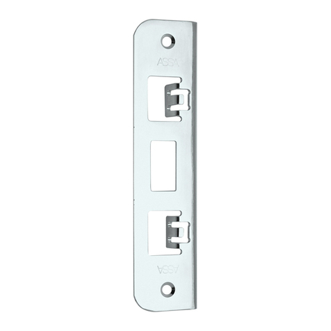
Slutbleck: EA300
803677 plant + 803711 magnet
804811 plant + 803711 magnet
[EN] Monotoring outputs:
- security bolt out
- security bolt in
- auxiliary lock locked / open
- door closed / open
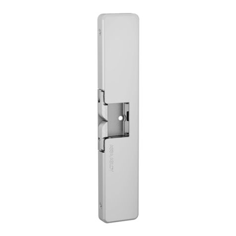
Striker plate: EA300
803677 flat strike + 803711 magnet
804811 flat strike + 803711 magnet
[RU] Выводы индикации:
- ригель повышенной наджности снаружи
- ригель повышенной наджности внутри
- дополнительный замок закрыт / открыт
- дверь закрыта / открыта
Запорная планка: EA300
803677 плоская планка + 803711 магнит
804811 плоская планка + 803711 магнит
EN 14846:2008 3C8D-L513
0809-CPR-1157 VTT-S-04768-13 Metal fire doors single
[SV] KABLAGE INSTRUKTIONER EL654, EL655
DATA KABEL EA216, 6 m, 9 * 0,14 mm2
BUSSTERMINATION 120 Ω
I ett bussnätverk är det nödvändigt att avsluta busslingan för att
undvika att reflektioner sänds. I det här systemet avhjälps detta
med ett motstånd. Observera att själva låshuset inte inbegrips
i bussterminering. Om låshuset är installerat med styrenhet
EA470 kan termineringen utföras med Dip omkopplarna i styr-
enheten.
Obesrvera! Om mer än en terminering i nätverket står i läge på
(ON) kan det medföra problem. Endast ett 120 Ωterminerings
motstånd är tillåtet.
INSTÄLLNING AV GRUPPER
Det är möjligt att dela nätverkets anordningar i två oberoende
logiska grupper. Låset är inställt till grupp 1 när den bygglade
kontakten inte är ansluten.
När den bygglade kontakten är ansluten ställs låset till grupp två.
Observera! När EL654/EL655 är ställt till att arbeta ensam (utan
daglås) i grupp två, skall den bygglade kontakten för blå ledning
klippas.
KOPPLING DAGLÅS EL654/655 OCH DAGLÅS
Det är möjligt att koppla EL654/EL655 tillsammans med ABLOY
låshus EL480, EL482, EL402 och EL490.
Kopplingen måste utföras med anslutningskabel, ABLOY EA235
eller EA236 beroende på låstyp (se sidan 9).
Daglåset aktiveras genom att ansluta konfigurations bygeln
enligt nedan:
- Anslut bygelkontakten till kontakten från EL654/EL655 (3-pin
AMP kontakt)
- Slå av strömmatningen till EL654/EL655.
Observera! Strömmatningen måste slås av varje gång du aktiverar
ett nytt låshus EL654/EL655.
[EN] CABLING INSTRUCTIONS EL654, EL655
DATA CABLE ABLOY EA216, 6 m, 9 x 0.14 mm2
BUS TERMINATION 120 Ω
In a bus network it is necessary to terminate the bus lines in
order to avoid transmitting reflections. In this system, it is
accomplished by one resistor. Please note that the lock case
itself does not include the bus termination, but if the lock case is
installed with EA470 control unit, the bus termination can be set
by DIP-switch in the control unit.
Note! If more than one termination in the network is switched
ON, this may cause problems. Only one 120 Ωtermination
resistor is allowed.
SETTING THE GROUPS
It is possible to split the network devices into two logically
independent groups. The lock is set to group 1 when the loop
connector is not connected.
When the loop connector is connected, the lock is set to group 2.
Note! When EL654/ EL655 is set alone (without auxiliary lock) in
group 2, the blue wire in the loop connector must be cut.
CONNECTION BETWEEN EL654/EL655 AND AUXILIARY LOCK
CASE
It is possible to connect EL654/EL655 together with lock cases
ABLOY EL480, EL482, EL402 and EL490.
The wiring must be implemented by using ABLOY connection
cables EA235 or EA236 depending on the lock type
(see page 9).
The auxiliary lock case is activated by using the configuration
connector loop connector as follows:
- Connect the loop connector to the EL654/EL655 cable (3-pin
AMP connector).
- Turn the power off from EL654/EL655.
Note! The power must be turned off everytime you activate a
new EL654/EL655 lock case.

