IS93 07/21
Copyright © 2021, ASSA ABLOY Accessories and Door Controls Group, Inc. All rights reserved. Reproduction in whole or in
part without the express written permission of ASSA ABLOY Accessories and Door Controls Group, Inc. is prohibited.
2
Model 93, Metal Frame
Before You Begin:
IMPORTANT:
• The Americans with Disabilities Act (ADA) requires that doors having door closers have an opening force not to
exceed 5 lbf.
• Door closer’s power size adjustment feature may require adjustment to its lowest setting to comply with ADA
opening force guidelines.
• ADA compliant closers may not latch doors, manufacturer does not guarantee latching on lower opening
force settings.
• A separate Rixson Surface Checkmate® or other door stop, supplied by others, is strongly recommended to
avoid damage to door closer and adjacent property.
• Doors should be hung on ball bearing or anti-friction hinges/pivots. Door must swing freely. For other hanging
means a special layout may be required, consult factory.
• Door and frame must be reinforced for attaching screws.
• All dimensions are given in inches (millimeters).
• An improperly installed or incorrectly adjusted door closer may cause property damage or personal injury and
will void product warranty.
• To avoid personal injury, DO NOT DISASSEMBLE THIS DOOR CLOSER BODY.
• Door closers must be securely fastened to a prepared door and frame with fasteners provided.
• HOLD OPEN option not permitted to be installed in re door assemblies.
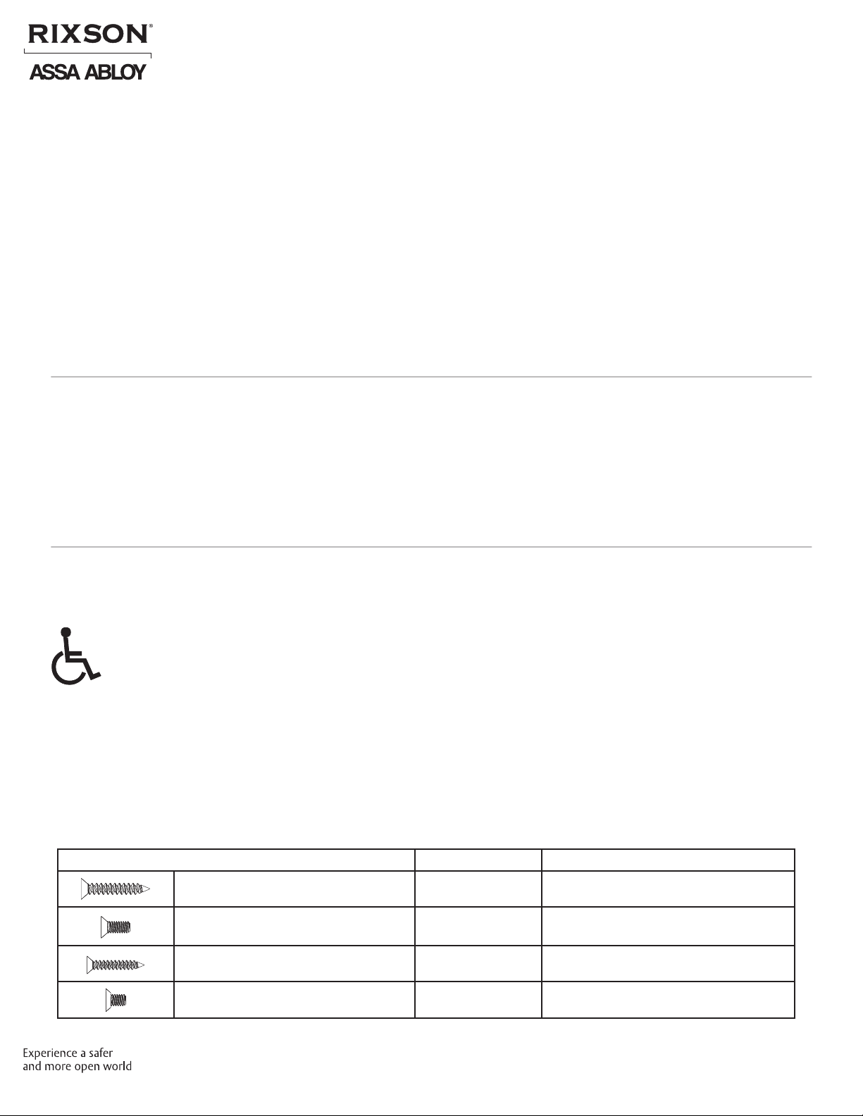
Mounting Hardware Door / Frame Drill
Closer, Top Pivot and Bottom Pivot:
#14 x 1-1/2" Wood 3/16" (4.76mm)
Closer, Top Pivot and Bottom Pivot:
1/4-20 x 5/8" Metal Drill #7 (.201 dia. or 5.10mm)
Tap 1/4-20
Track:
#14 x 1-1/4" Aluminum or Wood 3/16" (4.76mm)
Track:
1/4-20 x 7/16" Hollow Metal Drill #7 (.201 dia. or 5.10mm)
Tap 1/4-20
Contents
Important.............................................................................................. 2
Before You Begin ....................................................................................... 2
Mounting Hardware and Drill Table ..................................................................... 2
Supplied Fasteners . . . . . . . . . . . . . . . . . . . . . . . . . . . . . . . . . . . . . . . . . . . . . . . . . . . . . . . . . . . . . . . . . . . . . . . . . . . . . . . . . . . . . 3
Pivot Installation ....................................................................................... 4
Track Installation . . . . . . . . . . . . . . . . . . . . . . . . . . . . . . . . . . . . . . . . . . . . . . . . . . . . . . . . . . . . . . . . . . . . . . . . . . . . . . . . . . . . . . . 6
Closer Installation ...................................................................................... 7
Adjustments ........................................................................................... 9
Closer and Pivot, Metal Frame Template . . . . . . . . . . . . . . . . . . . . . . . . . . . . . . . . . . . . . . . . . . . . . . . . . . . . . . . . . . . .11-12


