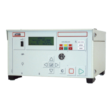
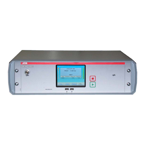
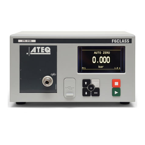
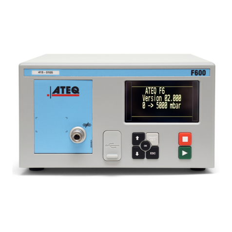
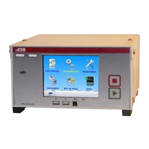
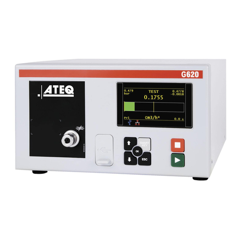
ATEQ F670 User manual

ATEQ F670
Quick Start Guide

QSG_F670_363.00_EN_01_2021-02-09
2/42
Table of contents
Safety advisory / Warranty
Good practices and safety instructions 4
Air quality requirements 5
Preamble
ATEQ F670, an universal leak tester 6
Leak test 7
Principe of a cycle 8
Your ATEQ F670
Front panel 9
Connectors on the back panel (with all options) 10
Power supply connectors 12
Digital links 12
Analog outputs 15
Digital inputs/outputs 16
Pneumatic connectors 19
Pneumatics configuration 22
User interface
Overview 30
Keys 30
Display 31
Starting up
Power up 33
Preparing a program 33
Modifying a parameter 34
Selecting a program or a sequence 35
Starting and stopping current cycle 35
User adjustments
Options of the menus 36
Specifications
Characteristics 42

QSG_F670_363.00_EN_01_2021-02-09
3/42
ATEQ - Measurement Solution, Global Leader.
ATEQ
15, rue des Dames, Z.I.
78340 LES CLAYES-SOUS-BOIS
FRANCE
ateq.com
T.: +33 1 30 80 1020
F.: +33 1 30 54 1100
ATEQ K.K.
3 –41 ATEQ Building, Ikehata
Chiryu-city, Aichi-pref
JAPAN
ateq.co.jp
T.: +81 566-84-4670
F.: +81 566-84-4680
ATEQ China
98 Jian Peng Lu
Shanghai
CHINA
ateq.com.cn
T.: +86 21 6763 9508
F.: +86 21 6763 9528
ATEQ SYSTEMS ANALYSIS TAIWAN CO.,
LTD.
NO. 3, LAN 223, San Jia Dong Street
40642, TAICHUNG
TAIWAN
ateq.com.tw
T.: +886 4 2437 5278
F.: +886 4 2437 3675
ATEQ CORP.
35980 Industrial Road Suite L
Livonia MI 48150
UNITED STATES
atequsa.com
T.: +1 734-838-3100
F.: +1 734-838-0644
We continuously work on improving our products. This is why information contained in this
manual, the device and the technical specifications may be modified without prior notification.
Pictures and figures in this manual are non-contractual.

QSG_F670_363.00_EN_01_2021-02-09
4/42
Safety advisory / Warranty
GOOD PRACTICES AND SAFETY INSTRUCTIONS
Safety recommendations
If the device is supplied with 100 / 240 V AC, it is mandatory to connect it to the ground with
a good link to the ground, to protect against electric hazard or electrocution.
It is dangerous to change the status of the outputs.
They can control power actuators or other equipment (mechanical, pneumatic, hydraulic,
electrical or other) which can cause serious personal injury and damage to surrounding
material.
For safety and quality measurement reasons, it is important, before powering on the device,
to ensure that it is air supplied with a minimum operating pressure (0.6 MPa ± 15%).
Recommendations for the test environment
Keep the test area as clean as possible.
Recommendations for operators
ATEQ recommends that the operators who use the devices have training and a level of
qualification that correspond to the job to perform.
General recommendations
—Read the user manual before using the device.
—All electrical connections to the device must be equipped with safety systems (fuses,
circuit breakers, etc.) adapted to the needs and in accordance with the applicable
standards and rules.
—To avoid electromagnetic interference, electrical connections to the device must be
shorter than 2 meters.
—Power supply plug must be grounded.
—Disconnect the device from the mains before performing any maintenance work.
—Shut off the compressed air supply when working on the pneumatic assembly.
—Do not open a connected device.
—Avoid splashing water on the device.
ATEQ is at your disposal for any information concerning the use of the device under
maximum safety conditions.
We draw your attention to the fact that ATEQ cannot be held responsible for any accident
related to a misuse of the measuring instrument, the workstation or non-compliance of the
installation with safety rules.
In addition, ATEQ declines any responsibility for the calibration or the fitting of their
instruments that is not done by ATEQ.
ATEQ also declines any responsibility for any modification (program, mechanical or
electrical) of the device done without their written consent.
QSG_F670_363.00_EN_01_2021-02-09
5/42
AIR QUALITY REQUIREMENTS
The air supplied into the device must be clean and dry. Even though the device is provided
with a filter, the presence of dust, oil or impurities may cause malfunction.
Air quality requirements according to ISO standard 8573
The air must be clean and dry.
The presence of impurities, oil or humidity in the air may cause deterioration which will not
be covered by the warranty.
When the instrument is working in vacuum conditions, impurities must be prevented from
being drawn into its internal components.
For this purpose, we strongly recommend that a suitable airtight filter is installed between
the part under test and the instrument.
ATEQ recommends the following characteristics for the air supplied into the device.
Recommended additional equipment
ATEQ recommends the installation of this additional equipment:
—Air dryer to provide dry air at less than - 40°C dew point
—25 microns and 1/100 microns double filter
Air characteristics
ISO standard 8573 class
Grain size and concentration
0.1 μm and 0.1 mg/m3
Class 1
Dew point under pressure
- 40°C dew
Class 2
Maximum concentration of oil
0.01 mg/m3
Class 1

QSG_F670_363.00_EN_01_2021-02-09
6/42
Preamble
ATEQ F670, AN UNIVERSAL LEAK TESTER
ATEQ F670 is a leak detector that tests the airtightness of parts.
ATEQ F670 can memorise 128 different test programs.

QSG_F670_363.00_EN_01_2021-02-09
7/42
LEAK TEST
Direct measurement principle
The part under test
3
and the reference part
5
are filled to an identical pressure. A
differential sensor
4
measures the pressure variation between the part under test
3
and the reference part
5
. In some applications, the reference part can be replaced by
a cap.
1 Device
2 Pressure sensor
3 Part under test
4 Differential pressure sensor
5 Reference part
Desensitized test
This mode is used for the measurement of large leaks, when the reject level required is
above the full scale of the differential sensor.
The test pressure is applied to the input of the part under test 3. The measurement is
performed by the pressure sensor 2.
1 Device
2 Pressure sensor
3 Part under test
4 Cap on the reference connector
Other type of tests are available in option (Burst test, Volume, Operator …).

QSG_F670_363.00_EN_01_2021-02-09
8/42
PRINCIPLE OF A CYCLE
The measurement cycle is made of 4 main phases: fill, stabilization, test, dumping.
A Pressure auto zero additional phase 0can be placed at the start or at the end of a cycle,
depending on the requirement of the operator.
0 Waiting phase
1 Fill phase
2 Stabilization phase
3 Test
4 Dumping

QSG_F670_363.00_EN_01_2021-02-09
9/42
Your ATEQ F670
FRONT PANEL
The user interface is located on the front panel.
1 Device name
2 Serial number
3 Display
4 Parameters lock key (option)
5 RS232 connector (option)
6 Mechanical regulator (option)
7 Cycle keys
8 Navigation keys
9 USB connectors
10 Mechanical regulator (option)
11 Quick connector (option)
For more information, refer to User interface.
5
1
2
3
4
6
7
8
9
10
11

QSG_F670_363.00_EN_01_2021-02-09
10/42
CONNECTORS ON THE BACK PANEL (WITH ALL OPTIONS)

QSG_F670_363.00_EN_01_2021-02-09
11/42
Ref
Name
Description
1
J12
Printer RS232 connector / Modbus (option)
2
J1
Analog outputs –test pressure and leak pressure (option)
3
J8
Program selection extension connector (option)
4
J10*
Extender (not operational)
5
J14*
Extender (not operational)
6
J5
Fieldbus connector
7
-
Input connector to the air filter (valves or regulator air supply)
8
-
0.6 MPa valves air supply input (1 MPa range)
9
-
Optional fitting according to special configuration
10
-
Optional fitting according to special configuration
11
-
Vacuum supply input (option)
12
R
Reference output
13
P2
External back pressure connector (option)
14
-
Test part exhaust (also for test pressure sensor auto zero)
15
ATEQ
Air supply energy information
16
-
Part number / Serial number
17
P1
External back pressure connector (option)
18
T
Test output
19
V
Volume for calibration check (option)
20
Y2
T1+T2 tests output (option)
21
B
B automatic connector option
22
Y1
T1+T2 tests output (option)
23
A
A automatic connector option
24
J6
Fieldbus connector
25
J4*
Extender (not operational)
26
J15
Outputs code board connector (digital inputs/outputs) (option)
27
J11*
Extender (not operational)
28
J9
Relay board connector (digital inputs/outputs) (option)
29
J3*
Not operational
30
J2*
Not operational
31
-
Ground
32
J7
Connector for 100 / 240 V AC power supply
33
J13
Connector Profibus (option)
*
These connectors are not operational. They are provided for future development of our
devices
.

QSG_F670_363.00_EN_01_2021-02-09
12/42
POWER SUPPLY CONNECTORS
Internal supply only
100 / 240 V AC connector (J7) (option)
The device can be connected to a 100 / 240 V AC power supply.
This connector has an ON/OFF button.
It is mandatory to connect the device to the ground with a good link to the ground, to protect
against electric hazard or electrocution.
1 ON
0 OFF
DIGITAL LINKS
PC USB connectors (on front face)
USB connectors can be used for connecting miscellaneous compatible USB devices.
The USB connectors are located under the rubber cover 1(see figure).
1 Rubber cover
2 USB connector to PC
3 USB connector to USB key
Do not connect two USB devices at the same time.
Do not use a cable longer than 2 m.
Push the rubber cover 1slightly forward for an easy access to USB connectors 2and 3.
Only use this connection for temporary communication. Connection to a PC cannot be used
permanently because the communication can be disconnected by the PC.

QSG_F670_363.00_EN_01_2021-02-09
13/42
Printer RS232 connector (J12) / Modbus (option)
RS232 - SubD 9 pins male connector (printer)
RS232 for printer, bar code reader, PC connection.
Profibus connector (J13) (option)
SubD 9 pins female connector (Profibus) option
Profibus: SubD 9 pins female connector.
Devicenet connectors (J5) (J6) (option)
M12 type connector - 5 pins male connector (J5) (Devicenet input)
For connection to others ATEQ devices.
Pin number
Signal
1
Not used
2
RXD data input
3
TXD data input
4
Not used
5
Ground
6
Not used
7
RTS request to send
8
CTS clear to send
9
Not used
Pin number
Signal
1
PE (ground)
2
Not used
3
Data line A
4
CNTR - A (repeater control
signal)
5
DGND (logic ground)
6
VP (supply)
7
Not used
8
Data line B
9
Not used
Pin number
Signal
1
Drain
2
V+
3
V-
4
CAN_H
5
CAN_L
J13

QSG_F670_363.00_EN_01_2021-02-09
14/42
M12 type connector - 5 pins female connector (J6) (Devicenet output)
For connection to other ATEQ devices.
Profinet connectors (J5 + J6) (option)
M12 D coded type connector - 4 pins female connector (J5 + J6)
Ethernet connector (J5 + J6) (option)
Standard connection Ethernet TCP / IP protocol.
One of these network protocols is available:
—Ethernet IP
—Profinet
—Ethercat (J5 = Input, J6 = Output)
Pin number
Signal
1
Drain
2
V+
3
V-
4
CAN_H
5
CAN_L
Pin number
Signal
1
Ethernet Tx + (Transmit Data +)
2
Ethernet Rx + (Receive Data +)
3
Ethernet Tx - (Transmit Data -)
4
Ethernet Rx - (Receive Data -)

QSG_F670_363.00_EN_01_2021-02-09
15/42
ANALOG OUTPUTS
M12 type connector –8 pins female connector (J1) (option)
Pin number
Description
1
Ground pressure
2
0-10V DC pressure
3
Ground Pressure (Diff)
4
0-10V DC Pressure (Diff)
5
Signal contact event (option)
6
Ground contact event (option)
7
Not connected
8
Not connected

QSG_F670_363.00_EN_01_2021-02-09
16/42
DIGITAL INPUTS/OUTPUTS
The 24V DC power supply for the digital inputs can be provided by 2 means:
—The internal power supply of the device (0.3 A max)
—An external power supply provided by the customer
Inputs default mode is PNP. NPN mode is available on request.
Relay board connector (J9) (option)
Characteristics
—Inputs
• Activation: + 24 V DC
—Outputs
• Dry contacts
• 60 V AC / DC max - 200 mA max.
Pin number
Inputs / outputs
Description
1
Input 1
RESET
2
+ 24 V DC
Common
3
Input 2
START
4
+ 24 V DC
Common
5
Input 3
Program selection
6
Input 4
Program selection
7
Input 5
Program selection
8
Input 6
Program selection
9
Input 7
Program selection (programmable input)
10
Output
Common floating output
11
Output
Pass part
12
Output
Test fail part
13
Output
Reference fail part
14
Output
Warning
15
Output
End of cycle
16
0 V
Ground
J9

QSG_F670_363.00_EN_01_2021-02-09
17/42
Program selection extension connector (J8) (option)
The J8 connector is an extension of the J9 connector that enables the selection of 128
programs.
Characteristics
—Inputs
• Activation: + 24 V DC.
Program selection (J8 and J9)
The connectors J8 and J9 (option) enable you to select a program from digital inputs.
Combinations of connector pins to activate for program selection.
* X is equal to 0 or 1 in function of the program number.
Pin number
Inputs/outputs
Description
1
Input 8
Program selection from 33 to 64 (programmable input)
2
Input 9
Program selection from 65 to 128 (programmable input)
Program
number
J9
J8
Pin 5
(input 3)
Pin 6
(input 4)
Pin 7
(input 5)
Pin 8
(input 6)
Pin 9
(input 7)
Pin 1
(input 8)
Pin 2
(input 9)
1
0
0
0
0
0
0
0
2
1
0
0
0
0
0
0
3
0
1
0
0
0
0
0
4
1
1
0
0
0
0
0
5
0
0
1
0
0
0
0
6
1
0
1
0
0
0
0
7
0
1
1
0
0
0
0
8
1
1
1
0
0
0
0
9
0
0
0
1
0
0
0
10
1
0
0
1
0
0
0
11
0
1
0
1
0
0
0
12
1
1
0
1
0
0
0
13
0
0
1
1
0
0
0
14
1
0
1
1
0
0
0
15
0
1
1
1
0
0
0
16
1
1
1
1
0
0
0
17 to 32
X*
X
X
X
1
X
X
33 to 64
X
X
X
X
X
1
X
65 to 128
X
X
X
X
X
X
1
J8

QSG_F670_363.00_EN_01_2021-02-09
18/42
Valve codes and auxiliary outputs board connector (J15)
(option)
Characteristics
—Outputs:
• 24 V DC - 100 mA max per output.
—Inputs:
• Activation: + 24 V DC.
Pin number
Inputs / outputs
Description
1
+ 24 V DC
Common (outputs 1, 2,3)
2
Output 1
Open collector
3
Output 2
Open collector
4
Output 3
Open collector
5
+ 24 V DC
Common (outputs 4, 5, 6)
6
Output 4
Open collector
7
Output 5
Open collector
8
Output 6
Open collector
9
Input 1
Programmable input
10
Input 2
Programmable input
11
Input 3
Programmable input
12
Input 4
Programmable input
13
Input 5
Programmable input
14
0 V
Ground
15
Input 6
Programmable input
16
0 V
Ground
J15

QSG_F670_363.00_EN_01_2021-02-09
19/42
PNEUMATICS CONNECTORS
Pneumatic connectors used to connect the part under test are located on the back panel of
the device.
Pneumatic supply
The pneumatic supply has to meet specific requirements recommended by ATEQ. Refer to
Good practices and safety instructions section.
A specific filter may be necessary.
The air is supplied via the filter located on the back panel of the device.
Metal air filter
The metal filter is used for 1MPa range.
The maximum pressure admissible is
1.2 MPa.
Plastic air filter
The plastic filter is used for 0.5 MPa
range (direct and indirect modes) or 2
MPa range (indirect mode only).
The maximum pressure admissible is
690 kPa.

QSG_F670_363.00_EN_01_2021-02-09
20/42
Quick connector (on front face) (option)
Use this function to check the
calibration.
As this connector is part of the measurement circuit, all its connections must be air tight.
Test and reference outputs
1 Test connector
2 Reference connector
3 Not used
4 Exhaust output
5 Pressurization output
Metallic fitting available for test (1) and
reference (2) connectors:
—2.7/4 mm
—3/5 mm
—4/6 mm
—6/8 mm.
Differential sealed part connectors (option) (V1 and V2)
External volume (closed tube) connection.
Metallic fitting available for V1 and V2
connectors:
—2.7/4 mm
Other manuals for F670
1
Table of contents
Other ATEQ Test Equipment manuals
Popular Test Equipment manuals by other brands

Schrader International
Schrader International TPMS PAD user manual

multicomp pro
multicomp pro MP780834 user manual

YOKOGAWA
YOKOGAWA DL7440 Operation guide

PCE Instruments
PCE Instruments PCE-900 user manual

Lutron Electronics
Lutron Electronics DL-9954 Operation manual

Ibiza
Ibiza STROBE-150 instruction manual