ATEQ F610 Instruction manual

QUICK START
ATEQ F610
Version 1.0
(Photo no contractual)
Reference: MR-36200C-U

REVISIONS OF THE ATEQ F610 USER MANUAL
Due to continuing improvements, the information contained in this user manual, the features and design of
this device are subject to be changed without prior notice.
Edition/Revision Reference Date
Week/Year Chapters up dating
First edition MR-36200A-U 15/2013 -----
Second edition MR-36200C-U 20/2013 Minor corrections. C Indice to be the
same as the F620 (B indice cancelled).

Quick start - F610
MR-36200C-U Quick start manual ATEQ F610 Page 1/24
Quick start manual
TABLE OF CONTENTS
TABLE OF CONTENTS..................................................................................................1
PREAMBULE..................................................................................................................2
1. DEFINITION OF THE ATEQ F610 ......................................................................................................2
2. MEASUREMENT CHARACTERISTICS..............................................................................................2
3. THE MAIN TYPES OF MEASUREMENT............................................................................................3
4. THE THREE TYPES OF TEST ............................................................................................................3
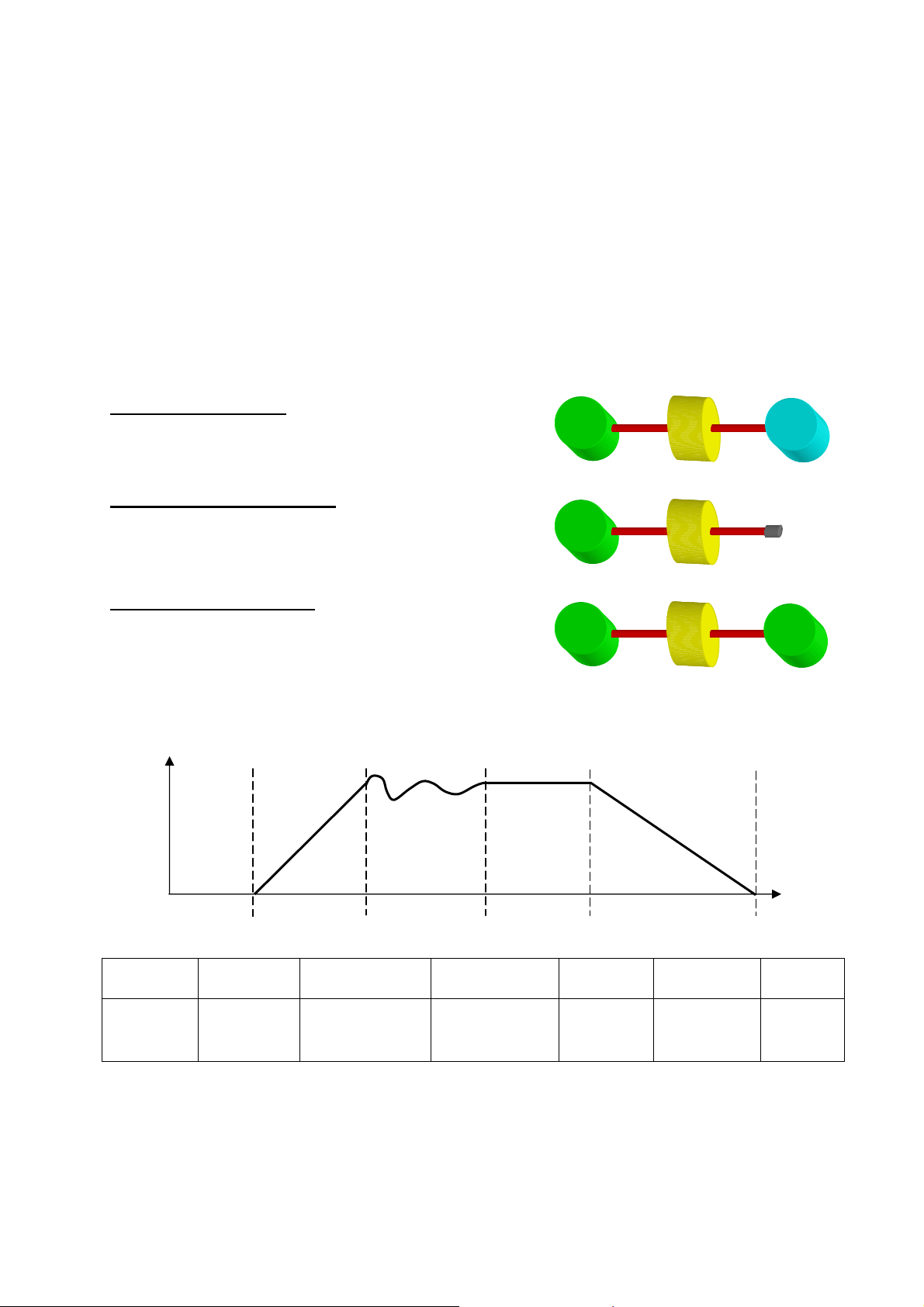
5. MEASUREMENT CYCLE ....................................................................................................................3
INSTALLATION ..............................................................................................................4
1. APPEARANCE OF THE ATEQ F610..................................................................................................4
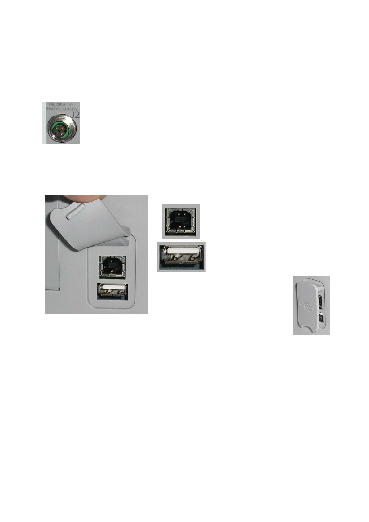
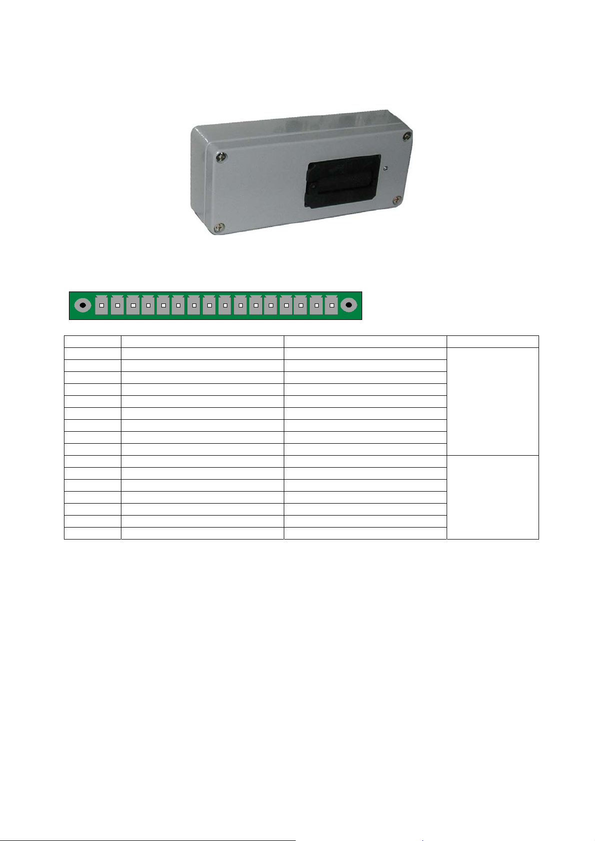
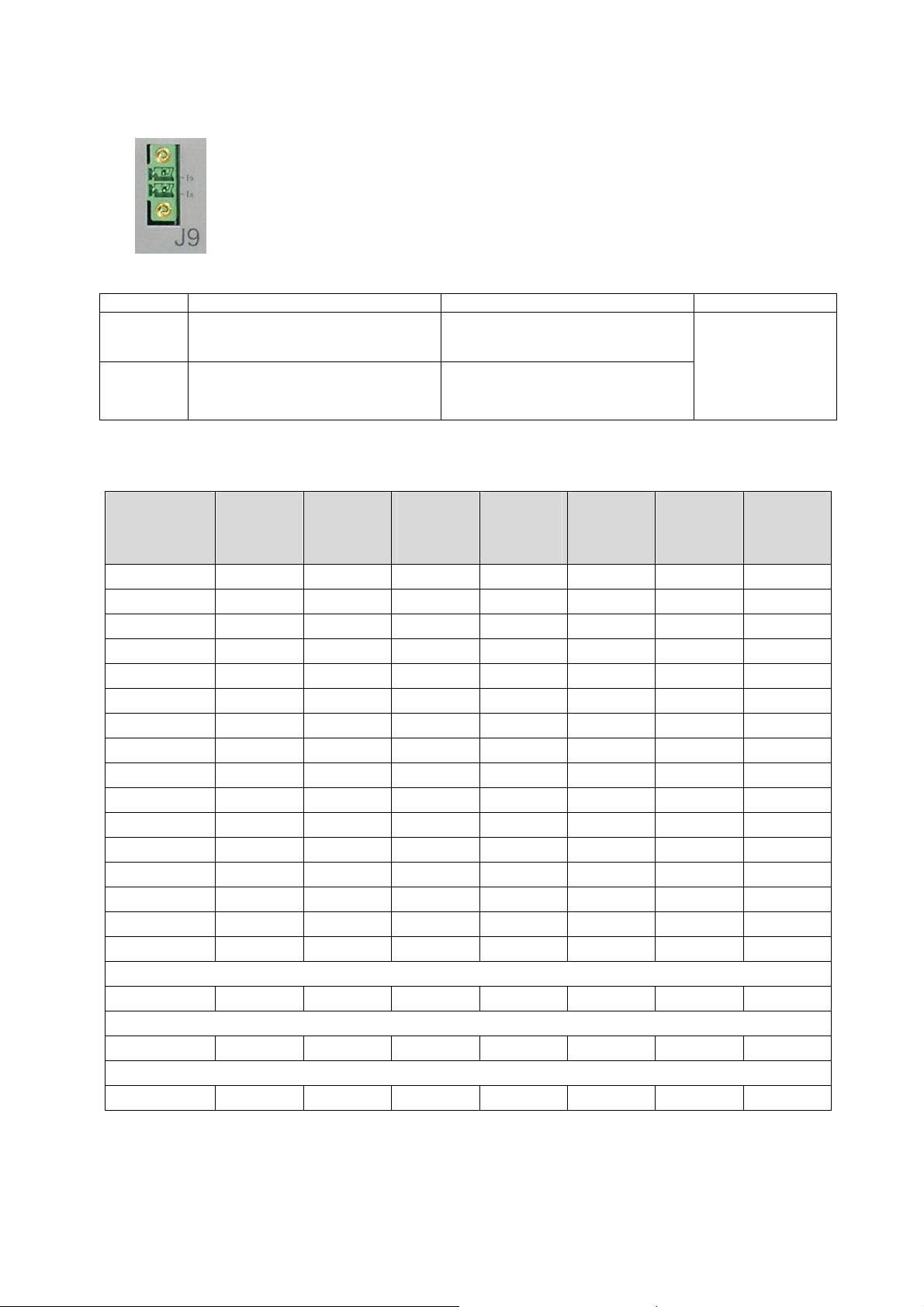
2. ELECTRICS CONNECTORS ..............................................................................................................5
3. PNEUMATIC SUPPLY.........................................................................................................................9
4. PNEUMATIC CONNECTORS ...........................................................................................................10
USER INTERFACES.....................................................................................................11
1. CYCLE KEYS ....................................................................................................................................11
2. TOUCHES DE NAVIGATION ............................................................................................................11
STARTING UP AND ADJUSTMENTS..........................................................................13
1. TEST MENU.......................................................................................................................................13
2. MAIN MENU.......................................................................................................................................13
3. LOCK PARAMETERS .......................................................................................................................13
4. PROGRAMS MANAGEMENT...........................................................................................................14
5. PARAMETERS ..................................................................................................................................15
6. START AND STOP MEASUREMENT CYCLE .................................................................................16
7. FUNCTIONS ......................................................................................................................................17
OTHERS MENUS..........................................................................................................18
1. SPECIAL CYCLES ............................................................................................................................18
2. MENU CONFIGURATION .................................................................................................................19
3. SERVICE MENU MAINTENANCE ....................................................................................................20
4. RESULTS MENU ...............................................................................................................................20
5. USB MENU ........................................................................................................................................20
ACCESSORIES AND CHARACTERISTICS.................................................................21
1. ACCESSORIES PROVIDED .............................................................................................................21
2. ACCESSORIES IN OPTION..............................................................................................................21
3. TECHNICAL CHARACTERISTIC OF THE F610 ..............................................................................22
ERRORS AND FAULTS ...............................................................................................23
1. ERROR MESSAGES .........................................................................................................................23
2. IN CASE OF OPERATION DOUBT ..................................................................................................23
INDEX ...........................................................................................................................24
Due to continuing improvements, the information contained in this user manual,
the features and design of this device are subject to be changed without prior
notice.

Quick start - F610
MR-36200C-U Quick start manual ATEQ F610 Page 2/24
PREAMBULE
1. DEFINITION OF THE ATEQ F610
The ATEQ F610 is a compact air/air
leak detector used to test the air-
tightness of parts. The method used
is based on the measurement of a
small variation or drop in differential
pressure between the test and
reference parts, when both are filled
to an identical pressure.
TEST
PART
REFERENCE
PART
DIFFERENTIAL
SENSOR
PIEZO
SENSOR
TEST
PRESSURE
2. MEASUREMENT CHARACTERISTICS
2.1. PRESSURE DROP MEASUREMENT
RANGE ACCURACY RESOLUTION
Maximum
0 – 500 Pa +/- (2,5% of the pressure + 1 Pa) 0,1 Pa
2.2. TEST PRESSURE MEASUREMENT
RANGE ACCURACY RESOLUTION
Maximum
F.S. = 200 mbar +/- (1,5% of the pressure+ 0,2 hPa) 0,1 % F.S.
0.2 < F.S. ≤5 bar +/- (1,5% of the pressure + 7.5 hPa) 0,1 % F.S.
5 < F.S. ≤10 bar +/- (1,5% of the pressure + 15 hPa) 0,1 % F.S.
F.S. = Full scale.

Quick start - F610
MR-36200C-U Quick start manual ATEQ F610 Page 3/24
3. THE MAIN TYPES OF MEASUREMENT
Direct measurement, indirect measurement and sealed component measurement.
These three methods apply to measurements taken both under pressure and in vacuum
conditions.
The configuration is determined by the application and must be carried out prior to the
use of the instrument.
4. THE THREE TYPES OF TEST
Test with reference: measurement of a pressure
variation between a test part and a reference part.
TEST
PART
REFERENCE
PART
DIFFERENTIAL
SENSOR
Test without reference: measurement of a
variation in pressure between a test part and a
sealing connector on the reference side.
TEST
PART
CAP
DIFFERENTIAL
SENSOR
Test with central zero: test of two parts at the
same time. One part is connected to the test side
and the other to the reference side.
TEST
PART
DIFFERENTIAL
SENSOR
TEST
PART
5. MEASUREMENT CYCLE
FILL STABILIZATION TEST DUMPWAIT
The measurement cycle consists of 5 phases:
1 2 3 4 5
Start Coupling
time Fill time Stabilization
time
Test
time
Dump
time
Cycle
end

Quick start - F610
MR-36200C-U Quick start manual ATEQ F610 Page 4/24
INSTALLATION
1. APPEARANCE OF THE ATEQ F610
1.1. FRONT FACE
1.2. CONNECTORS SIDE

Quick start - F610
MR-36200C-U Quick start manual ATEQ F610 Page 5/24
2. ELECTRICS CONNECTORS
2.1. SUPPLY THE DEVICE WITH 24 VDC -2AON M12 CONNECTOR
Two means are available to supply the device following its configuration.
Connect the power supply fitted with the device. This option is not
possible if the connector is used for the Fieldbus network.
¾Pin 2 : + 24 V DC.
¾Pin 4 : masse 0 V.
2.2. USB CONNECTOR (FRONT FACE)
Allows the connection of miscellaneous compatibles
USB devices. The connectors are located under the
rubber cover.
USB connector to plug a PC.
USB connector to plug an UBS
memory key or a remote control.
The USB connector rubber cover can
be slightly deviated to the front for easy
access to connectors.

Quick start - F610
MR-36200C-U Quick start manual ATEQ F610 Page 6/24
2.3. RS232 CONNECTOR PRINTER /MODBUS OR PROFIBUS
2.3.1. Connector in RS232 mode
51
9
6
RS232: SubD 9 points male connector.
To plug a printer or a PC.
Pin 1 Not used Pin 4 Not used Pin 7 RTS request to send
Pin 2 RXD data input Pin 5 Earth/Ground Pin 8 CTS clear to send
Pin 3 TXD data output Pin 6 Not used Pin 9 Not used
2.3.1. 1) Examples of RS232 cables
1
2
3
4
5
6
7
8
9
1
2
3
4
5
6
7
8
9
ATEQ Use
r
9 pin SubD
connector
9 pin SubD
connector
RX
TX
GND
RTS
CTS
RX
T
X
GND
RTS
CTS
1
2
3
4
5
6
7
8
9
1
2
3
4
5
6
7
8
A
TEQ User
25
9 pin SubD
connector
25 pin SubD
connector
RX
TX
GND
RTS
CTS
RX
T
X
GND
RTS
CTS
2.4. ANALOG OUTPUTS (OPTION)
Connection for analog outputs.
2 1
4
3
¾Pin 1: Leak (signal).
¾Pin 2: Leak (ground).
¾Pin 3: Pressure (signal).
¾Pin 4: Pressure (ground).

Quick start - F610
MR-36200C-U Quick start manual ATEQ F610 Page 7/24
2.5. OTHERS CONNECTORS
The following connectors are located under the gland cap:
2.5.1. Connector I/O all or nothing
1 2 3 4 5 6 7 8 9 10111213141516
Inputs / Outputs All or Nothing.
Pin Standard Mode Compact Mode
1 Input 1 RAZ Input 1 RAZ
2 Common (+ 24 V) Common (+ 24 V)
3 Input 2 START Input 2 START
4 Common (+ 24 V) Common (+ 24 V)
5 Input 3 Program selection Input 3 Program selection
6 Input 4 Program selection Input 4 Program selection
7 Input 5 Program selection Input 5 Program selection
8 Input 6 Program selection Input 6 Program selection
9 Input 7 Program selection Input 7 Program selection
Inputs
(Activation by
24 V DC)
Common
+ 24 V = 0,3 A
maximum
10 Floating common output Floating common output
11 Output 1 Pass part Output 1Pass part cycle 1
12 Output 2 Fail Test part Output 2 Fail part cycle 1 + Alarm
13 Output 3 Fail reference part Output 3 Pass part cycle 2
14 Output 4 Alarm Output 4 Fail part cycle 2 + Alarm
15 Output 5 End of cycle Output 5 End of cycle
16 0 V 0 V
Outputs dry
contacts
60V AC / DC Max
200mA Max
The compact mode is a software function which is activated in the CONFIGURATION /
AUTOMATISM / OUTPUTS CONFIG. / I/O / OUTPUT… menu.

Quick start - F610
MR-36200C-U Quick start manual ATEQ F610 Page 8/24
2.6. PROGRAM SELECTION EXTENSION CONNECTOR (OPTION)
The J8 connector is to extend the selection to 128 programs.
Pin Standard Mode Compact Mode
1 Input 8 Program selection Input 8 Program selection
33 to 64.
2 Input 9 Program selection Input 9 Program selection
65 to 128
Inputs
(Activation by
24 V DC)
Common
+ 24 V = 0,3 A
maximum
Combinations of pins to activate to select programs
Program
number
I/Oconn
Pin 5
(input 3)
I/O Conn
Pin 6
(input 4)
I/O Conn
Pin 7
(input 5)
I/O Conn
Pin 8
(input 6)
I/O Conn
Pin 9
(input 7)
Extens
Pin 1
(input 8)
Extens
Pin 2
(input 9)
1 0 0 0 0 0 0 0
2 1 0 0 0 0 0 0
3 0
1 0 0 0 0 0
4 1 1 0 0 0 0 0
5 0 0 1 0 0 0 0
6 1 0 1 0 0 0 0
7 0
1 1 0 0 0 0
8 1 1 1 0 0 0 0
9 0 0 0 1 0 0 0
10 1 0 0 1 0 0 0
11 0
1 0 1 0 0 0
12 1 1 0 1 0 0 0
13 0 0
1 1 0 0 0
14 1 0 1 1 0 0 0
15 0
1 1 1 0 0 0
16 1 1 1 1 0 0 0
17 à 32 x x x x 1 0 0
33 à 64 x x x x x 1 0
65 à 128 x x x x x x 1
With xwho takes the 0 or 1 value in function of the program number to be called.

Quick start - F610
MR-36200C-U Quick start manual ATEQ F610 Page 9/24
2.7. CONNECTOR OUTPUT CODES /ANALOG (OPTION)
1 2 3 4 5 6 7 8 9 10111213141516
Output codes / analogue
outputs / temperature sensor.
Pin 1 COMMUN (Outputs 1, 2, 3) + 24 V DC
Pin 2 Output n°1, open collector
Pin 3 Output n°2, open collector
Pin 4 Output n°3, open collector
Pin 5 COMMON (Outputs 4, 5, 6) + 24 V DC
Pin 6 Output n°4, open collector
Pin 7 Output n°5, open collector
Pin 8 Output n°6, open collector
Output
codes
24V DC
100mA Max
Pin 9 Input 0 (NPN or PNP)*
Pin 10 Input 1 (NPN or PNP)*
Pin 11 Input 2 (NPN or PNP)*
Pin 12 Input 3 (NPN or PNP)*
Inputs
Pin 13 Input 4 (NPN or PNP)*
Pin 14 Ground
Pin 15 Input 5 (NPN or PNP)*
Pin 16 Ground
Analogue
outputs
24 V DC
8
7
6
5
4
3
2
1
0,1 A max
Charge / Load
Obligatory
diode for an
inductive load.
* Inputs NPN or PNP following the strap position on the board.
3. PNEUMATIC SUPPLY
Air supply is via the filter located on the rear panel of the Air supply
is via the filter located on the rear panel of the instrument.
The air must be clean and dry.
The supply pressure must always be between 4 and 8 bar (400
kPa and 800 kPa).

Quick start - F610
MR-36200C-U Quick start manual ATEQ F610 Page 10/24
4. PNEUMATIC CONNECTORS
The pneumatics connectors are located on the low side.
4.1. AUTOMATIC CONNECTOR AAND B(OPTION)
To drive pneumatics caps.
4.2. PNEUMATICS TEST OUTPUTS
These outputs enable parts to be connected (test, reference). The pressurization output
is used for the addition of ATEQ accessories (Y valve).
Inputs / Outputs on the rear side of the F610:
Reference Output R
Pressurization Output
Test Output T
4.3. QUICK CONNECTORS (OPTION)
One quick connector may be mounted on the front panel of the
instrument.
This connector is to check the the calibration. It's used to check the
test circuit and enables, by use of a calibrated leak, calculation of the
equivalent pressure drop.
As this connector is part of the measurement circuit, all its
connections must be air tight.

Quick start - F610
MR-36200C-U Quick start manual ATEQ F610 Page 11/24
USER INTERFACES
Used to display measurements and
adjustable parameters.
1. CYCLE KEYS
KEY FUNCTION KEY FUNCTION
START key
Start a measurement
cycle.
RESET Key
Current measurement cycle
stop.
2. TOUCHES DE NAVIGATION
2.1. TOUCHES DE NAVIGATION
TOUCHE FONCTION
Scroll up or increase numerical values.
Scroll down or decrease numerical values
Opening a menu, entering a parameter, confirmation of a parameter.
Return to the previous menu or function, escape without modifying a
parameter
Programmable key by the user's preferences (see below).

Quick start - F610
MR-36200C-U Quick start manual ATEQ F610 Page 12/24
2.2. "SMART KEY"KEY FUNCTIONS
The "Smart Key" key can be programmed following the user preferences; this can have
a direct access to the selected function.
The programming for this key is done from the CONFIGURATION / MISCELLANEOUS /
SMART KEY menu.
The functions to assign are:
¾Special cycle menu: to access to the menu of special cycle selection.
¾Special cycle: to run the special cycle selected in the list of the availables ones.
¾Parameters: to access directly to the program parameters menu.
¾Program defined: to access directly to the selected program parameters.
¾Run program: to access directly to the current program parameterst (run
program).
¾Last results : to access directly to the test results menu.

Quick start - F610
MR-36200C-U Quick start manual ATEQ F610 Page 13/24
STARTING UP AND ADJUSTMENTS
1. TEST MENU
The test menu (or window) is displayed during a cycle measurement.
Test Unit
Last test result
Pass part
Fail part
Alarm
Time
remaining
Test reject
Value
Test
Results
Test
Pressure
Run
program
Test
Measurement
By pressing the "OK" key or "Esc" key gives access to the menu.
2. MAIN MENU
The main menu allows accessing to the different menus for the management of the
device.
Access to the USB
connection
functions
Access to the
service menu
Access to the
configuration menu
Access to the
results menu,
backup and display
Access to the
special cycle's
menu
Access to the
programs
parameters
3. LOCK PARAMETERS
For the parameters lock, one option is possible, among the 3 available, asked at the
device order.
¾No lock parameters.
¾Lock with a password to be defined when activated in the CONFIGURATION /
SECURITY / PASSWORD menu.
¾Lock with an USB stick (an ATEQ file must be copied on a USB stick). Once the
key is plugged, the parameters are unlocked.

Quick start - F610
MR-36200C-U Quick start manual ATEQ F610 Page 14/24
4. PROGRAMS MANAGEMENT
4.1. LEAK PROGRAM CREATION
From the main menu, select the
"PARAMETERS" menu by using the "Up"
and "Down" keys and then validate with
"OK".
Select the test program number to create
(or modify).
------------ for an empty program.
PARAMETERS
►Copy-Paste
Pr:01 -----------------
Pr:02 -----------------
Pr:03 -----------------
Pr:04 -----------------
Pr:05 -----------------
Pr:06 -----------------
Pr:07 -----------------
Then Select the test type: LEAK.
PARAM / TYPE
►LEAK TEST
BLOCKAGE
DESENSITIZED TEST
OPERATOR
The parameters menu is displayed, access
to each parameter by using the "Up" or
"Down" keys and validate with "OK" to edit
the parameter.
PARAM / Pr001
►TYPE : LEAK TEST
COUPL A : 0.0 s
FILL TIME : 0.0 s
STAB TIME : 0.0 s
TEST TIME : Inf. s
DUMP TIME : 0.0 s
Press. UNIT: bar
Max FILL : 0.000
Then by using the "Up" or "Down" keys
and adjust the parameter to the desired
value and validate with "OK".
PARAM / Pr001
TYPE : LEAK TEST
COUPL A : 0.0 s
FILL TIME : 0.0 s
STAB TIME : 0.0 s
TEST TIME : 2.0 s ◄
DUMP TIME : 0.0 s
Press. UNIT: bar
Max FILL : 0.000
Do the same process for all the others parameters.

Quick start - F610
MR-36200C-U Quick start manual ATEQ F610 Page 15/24
5. PARAMETERS
Main parameters to configure:
Fill time: Time to fill the part to the test pressure.
Stabilization time: Time to equalize the pressure between the TEST and
REFERENCE components.
Test time: Leak measurement time, it depends of the reject level value and
the work mode programmed.
Dump time: Time to back the part to the atmospheric pressure. Dump time
by default is zero.
Pressure unit: Pressure unit (bar, mbar, PSI, Pa, kPa, MPa).
Maximum fill: Maximum level of the fill pressure.
Minimum fill: Minimum level of the fill pressure.
Fill instruction:
Test pressure that the device will automatically regulate.
Remind: the input pressure must be at least greater than 100
kPa (1 bar) of the test pressure.
Reject unit : Leak unit displayed. If a flow unit is selected, two parameters
are added.
Test reject: Level for the test part is fail.
Reference reject:
Level for the reference part is fail (possible problem on this
part).
Note: when the reference reject value is 0, the device takes into
account the absolute value of the symmetrical test reject.
Functions :
Menu to access to the extended functions that must be
activated in the "More functions" menu.
Note: if no extended function has been activated from the
"More Functions" menus, the FUNCTION menu is empty.
Edition, duplication, deletion or copy of a test program, program number to start:
see the manuals CDROM for further information.

Quick start - F610
MR-36200C-U Quick start manual ATEQ F610 Page 16/24
6. START AND STOP MEASUREMENT CYCLE
6.1. RUN PROGRAM SELECTION
From the "Cycle" menu, press on the "Up"
or "Down" keys, the run program number
is displayed.
LEAK TEST
Pr 001
6.2. RUN A CYCLE
Press the START key to run the
measurement cycle.
Press the RESET key to stop the current
measurement cycle. The message "OK"
show the device is pending a new test
cycle.
At the end of the measurement cycle, the
test result is displayed.

Quick start - F610
MR-36200C-U Quick start manual ATEQ F610 Page 17/24
7. FUNCTIONS
7.1. PROGRAMS FUNCTIONS
The functions program allows improving the test measurement or suit the program or the
device to its environment.
These functions are:
¾Name
¾Program sequence
¾Units
¾Filter
¾Automatic Connector
¾Calibration check by volume
¾Transient Attenuation (ATR 0, 1 , 2 or
3)
¾Pre Fill Type
¾Fill Type
¾Valves Codes
¾Auxiliaries Outputs 24 V DC
¾End Of Cycle
¾Mini-Valve ----------------
¾Rework Limit
¾Sealed Components
¾N tests
¾Peak Hold
¾Reference Volume
¾Volume Compute
¾Temperature 1 Correction
¾Sign
¾Flow Level
¾No Negative
¾Absolute
¾Display Mode
¾Buzzer
These functions, to appear in the program, must be activated first in the
"More functions" menu.
Then it must validate and configure it in function menu of the program.
Each program can be individually personalized.

Quick start - F610
MR-36200C-U Quick start manual ATEQ F610 Page 18/24
OTHERS MENUS
1. SPECIAL CYCLES
To start a special cycle, select it in the "Special cycles" menu, then pres the key.
To stop it, press the key or for some cycles the end is automatic.
1.1. STANDARD SPECIAL CYCLES
Following the extended menus validations or following the device options, some des
special cycles can appear:
None: no special cycle selected.
Infinite fill: to pressurize the part with a infinite fill time.
Piezo auto zero: to run an auto zero cycle on the piezo sensor and on the electronic
pressure regulator.
Sealed component learning pass and fail part: this is pressure parameters learning
cycles for the sealed component mode. The pass part learning cycle is obligatory.
Calibration check: cycle to check the calibration by volume with a pass part.
Learning / Check: these cycles allow running a learn or a check cycle (or both) in
Pascal or Pascal/sec calibrate mode with a master leak.
ATR Learning: cycle to enter ATR parameters; this is to run at each switching on of the
device or after a long time without measurement.
Volume calculation: cycle to calculate the volume of the test circuit.
Other manuals for F610
1
Table of contents
Other ATEQ Test Equipment manuals