AVLink IPS-TC User manual

- -
- -
- -
-
IPS-Series v1.9

- 2 -
Please pay attention to the following points before installing and using the IPS system:
•The 10GbE Switch used with the IPS system must be from an
SDVoE-certified manufacturer and model.
•Before connecting the IPS to the 10GbE Switch, you must enable the
DHCP service of the Switch and confirm that the domain setting of the
DHCP service is correct to ensure that the IPS is operating in the
correct network environment.

- 3 -
For Warranty:
Please follow the warranty policy according to AV LINK’s local official distributor; during the
warranty period, it is recommended to keep your proof of purchase, accessories, and
packaging in place.
◼Follow all instructions marked on the device during use.
◼Provide proper ventilation and air circulation and do not use near water.
◼It is better to keep it in a dry environment.
◼Place the device on a stable surface (for example cart, stand, table, etc.).
◼The system should be installed indoors only. Install either on a sturdy rack or desk
in a well-ventilated place.
◼Make sure the rack is level and stable before extending a device from the rack if
necessary.
◼Make sure all equipment installed on the rack including power strips and other
electrical connectors are properly grounded.
◼Only use the power cord supported by the device.
◼Do not use liquid or aerosol cleaners to clean the device.
◼Always unplug the power to the device before cleaning.
◼Unplug the power cord during lightning or after a prolonged period of non-use to
avoid damage to the equipment.
◼Do not stand on any device while installing the device to the rack.
◼Do not attempt to maintain the device by yourself, any faults, please contact your
vendor.
◼Save this manual properly for future reference.
AV LINK GROUP LTD. reserves all rights. No part of this document may be reproduced in any form
or by any means without the written permission of the product manufacturer. Changes are made to
the information in this document periodically. They will be incorporated in subsequent editions. The
product manufacturer may make improvements and/or changes to the product described in this
document at any time.
All the registered trademarks referred to in this manual belong to their respective companies.
(Note: If there is any discrepancy with the latest version, please refer official website as the primary source of information)
AV LINK GROUP LTD.
Headquarters:
13F.-1, No. 2, Jian 8th Rd., Zhonghe Dist., New Taipei City 235, Taiwan (R.O.C.)
TEL: 886-2-8226-2268
E-mail: sales@cctch.com.tw
Website: https://avlinksystem.com

- 4 -
Table of Contents
Table of Contents----------------------------------------------------------------------------------------------- 4
Table of Figures------------------------------------------------------------------------------------------------- 6
Chapter 1 Overview ------------------------------------------------------------------------------------------10
1.1 Introduction ------------------------------------------------------------------------------------------10
1.2 IPS-TX ------------------------------------------------------------------------------------------------11
1.3 IPS-RX ------------------------------------------------------------------------------------------------12
1.4 IPS-AX ------------------------------------------------------------------------------------------------13
1.5 IPS-M--------------------------------------------------------------------------------------------------14
1.6 Packing -----------------------------------------------------------------------------------------------15
Chapter 2 Features -------------------------------------------------------------------------------------------16
Chapter 3 Specifications ------------------------------------------------------------------------------------17
Chapter 4 Components --------------------------------------------------------------------------------------20
4.1 Front Panel ------------------------------------------------------------------------------------------20
4.2 Rear Panel -------------------------------------------------------------------------------------------22
Chapter 5 Connection----------------------------------------------------------------------------------------24
5.1 IPS system Connections -------------------------------------------------------------------------24
5.2 IPS system for KVM -------------------------------------------------------------------------------25
5.3 IPS system for Video Wall -----------------------------------------------------------------------26
5.4 IPS system for Matrix Switch -------------------------------------------------------------------27
5.5 IPS system for Multi-view ------------------------------------------------------------------------28
5.6 Audio Routing ---------------------------------------------------------------------------------------29
Chapter 6 Operation------------------------------------------------------------------------------------------30
6.1 Switch Configuration ------------------------------------------------------------------------------30
6.2 Powering On-----------------------------------------------------------------------------------------30
6.3 Powering Off and Restarting --------------------------------------------------------------------30
6.4 Powering Sequence -------------------------------------------------------------------------------30
6.5 Hot Plugging-----------------------------------------------------------------------------------------30
Chapter 7 Website Configurations------------------------------------------------------------------------31
7.1 IPS-M--------------------------------------------------------------------------------------------------31
7.1.1 IPS-M Connections -----------------------------------------------------------------------31
7.1.2 IPS-M Information -------------------------------------------------------------------------31
7.2 General Setting -------------------------------------------------------------------------------------33
7.3 Routing------------------------------------------------------------------------------------------------34
7.3.1 Video------------------------------------------------------------------------------------------35
7.3.2 Audio ------------------------------------------------------------------------------------------36

- 5 -
7.3.3 RS-232 ---------------------------------------------------------------------------------------37
7.3.4 USB -------------------------------------------------------------------------------------------38
7.3.5 USB HID -------------------------------------------------------------------------------------39
7.3.6 IR-----------------------------------------------------------------------------------------------40
7.4 Layout -------------------------------------------------------------------------------------------------41
7.4.1 Layout component-------------------------------------------------------------------------42
7.4.2 Multi-view ------------------------------------------------------------------------------------48
7.4.3 Video Wall -----------------------------------------------------------------------------------48
7.4.4 Create a New Multi-view / Video Wall Layout --------------------------------------49
7.4.5 Create a New Device Group------------------------------------------------------------49
7.4.6 Duplicate Layout / Device Group ------------------------------------------------------49
7.4.7 Edit Layout ----------------------------------------------------------------------------------49
7.4.8 Layout Context Menu---------------------------------------------------------------------53
7.4.9 Delete Layout-------------------------------------------------------------------------------55
7.4.10 Delete Layout Device Group----------------------------------------------------------55
7.4.11 Remove Device from Region ---------------------------------------------------------56
7.4.12 Preview Source Video ------------------------------------------------------------------57
7.5 Show --------------------------------------------------------------------------------------------------58
7.5.1 Show Component -------------------------------------------------------------------------58
7.5.2 Create Show --------------------------------------------------------------------------------62
7.5.3 Duplicate Show ----------------------------------------------------------------------------63
7.5.4 Edit Show ------------------------------------------------------------------------------------63
7.5.5 Delete Show --------------------------------------------------------------------------------65
7.6 Schedule ---------------------------------------------------------------------------------------------66
7.6.1 Schedule Component --------------------------------------------------------------------67
7.6.2 Edit Schedule-------------------------------------------------------------------------------74
7.7 Devices -----------------------------------------------------------------------------------------------75
7.7.1 IPS-TX / IPS-RX / IPS-AX Device Component ------------------------------------75
7.7.2 IPS-M Controller Component-----------------------------------------------------------84

- 6 -
Table of Figures
Figure 1-1 IPS-TF ---------------------------------------------------------------------------------------------11
Figure 1-2 IPS-TC---------------------------------------------------------------------------------------------11
Figure 1-3 IPS-RF---------------------------------------------------------------------------------------------12
Figure 1-4 IPS-RC --------------------------------------------------------------------------------------------12
Figure 1-3 IPS-AF---------------------------------------------------------------------------------------------13
Figure 1-4 IPS-AC --------------------------------------------------------------------------------------------13
Figure 1-7 IPS-M----------------------------------------------------------------------------------------------14
Figure 4-1 IPS-TX front panel------------------------------------------------------------------------------20
Figure 4-2 IPS-RX front panel -----------------------------------------------------------------------------20
Figure 4-3 IPS-AX front panel -----------------------------------------------------------------------------20
Figure 4-4 IPS-M front panel -------------------------------------------------------------------------------20
Figure 4-5 IPS-TC rear panel ------------------------------------------------------------------------------22
Figure 4-6 IPS-TF rear panel ------------------------------------------------------------------------------22
Figure 4-7 IPS-RC rear panel------------------------------------------------------------------------------22
Figure 4-8 IPS-RF rear panel ------------------------------------------------------------------------------22
Figure 4-9 IPS-AC rear panel ------------------------------------------------------------------------------22
Figure 4-10 IPS-AF rear panel-----------------------------------------------------------------------------22
Figure 4-11 IPS-M rear panel ------------------------------------------------------------------------------23
Figure 5-1 IPS system connections ----------------------------------------------------------------------24
Figure 5-2 KVM application connections----------------------------------------------------------------25
Figure 5-3 Video Wall application connections --------------------------------------------------------26
Figure 5-4 Matrix Switch application connections ----------------------------------------------------27
Figure 5-5 Multi-view application connections---------------------------------------------------------28
Figure 5-6 IPS-TX Analog Audio Output routing ------------------------------------------------------29
Figure 5-7 IPS-TX Analog Audio Input routing---------------------------------------------------------29
Figure 7-1 IPS-M information ------------------------------------------------------------------------------31
Figure 7-2 IPS-M connections -----------------------------------------------------------------------------32
Figure 7-3 System Preference window------------------------------------------------------------------33
Figure 7-4 ROUTING configuration ----------------------------------------------------------------------34
Figure 7-5 Routing Table Grid component--------------------------------------------------------------34
Figure 7-6 Routing Table Crosshair highlight ----------------------------------------------------------34
Figure 7-7 Video type in ROUTING configuration ----------------------------------------------------35
Figure 7-8 Audio type in ROUTING configuration ----------------------------------------------------36
Figure 7-9 RS-232 type in ROUTING configuration -------------------------------------------37
Figure 7-10 USB type in ROUTING configuration------------------------------------------------38

- 7 -
Figure 7-11 USB HID type in ROUTING configuration ------------------------------------------39
Figure 7-12 IR type in ROUTING configuration -------------------------------------------------40
Figure 7-13 LAYOUT configuration-----------------------------------------------------------------------41
Figure 7-14 Layout Template window--------------------------------------------------------------------42
Figure 7-15 Layout File List --------------------------------------------------------------------------------43
Figure 7-16 Canvas Edit Area -----------------------------------------------------------------------------44
Figure 7-17 Layout Device Info----------------------------------------------------------------------------45
Figure 7-18 IPS-TX device card---------------------------------------------------------------------------46
Figure 7-19 IPS-RX device card --------------------------------------------------------------------------46
Figure 7-20 IPS-AX device card---------------------------------------------------------------------------46
Figure 7-21 Press Alt key device card -------------------------------------------------------------------46
Figure 7-22 Device card status ----------------------------------------------------------------------------47
Figure 7-23 Device card streaming status--------------------------------------------------------------47
Figure 7-24 Device card overheat status ---------------------------------------------------------------47
Figure 7-25 Multi-view Layout Template window -----------------------------------------------48
Figure 7-26 Video Wall Layout Template window ----------------------------------------------48
Figure 7-27 Source assignment in Multi-view layout ------------------------------------------------49
Figure 7-28 Display assignment in Multi-view layout ------------------------------------------------50
Figure 7-29 Layout Width and Height setting ----------------------------------------------------------50
Figure 7-30 Routing Mode setting ------------------------------------------------------------------------51
Figure 7-31 Layout Padding setting ----------------------------------------------------------------------51
Figure 7-32 Region X and Y coordination setting-----------------------------------------------------51
Figure 7-33 Region Width and Height setting ---------------------------------------------------------51
Figure 7-34 Effect of Add and Delete region -----------------------------------------------------------52
Figure 7-35 Effect of Zoom Out and Zoom In----------------------------------------------------------52
Figure 7-36 Edit layout / device group name ----------------------------------------------------------52
Figure 7-37 Context menu of layout----------------------------------------------------------------------53
Figure 7-38 Search bar of Source / Display card list ------------------------------------------------53
Figure 7-39 Card list’s context menu of Order by-----------------------------------------------------53
Figure 7-40 Card list’s context menu of Filter by------------------------------------------------------54
Figure 7-41 Layout File List’s context menu -----------------------------------------------------------54
Figure 7-42 Popup of DELETE LAYOUT confirmation message ---------------------------------55
Figure 7-43 Popup of DELETE LAYOUT DEVICE GROUP confirmation message ---------55
Figure 7-44 Popup of REMOVE DEVICE confirmation message --------------------------------56
Figure 7-45 Preview source video ------------------------------------------------------------------------57
Figure 7-46 SHOW configuration -------------------------------------------------------------------------58
Figure 7-47 Show File List ----------------------------------------------------------------------------------58

- 8 -
Figure 7-48 Layout with Specific Device Group List of show --------------------------------------59
Figure 7-49 Popup of Layout Library (Multi-view) ----------------------------------------------------60
Figure 7-50 Layout Detail -----------------------------------------------------------------------------------60
Figure 7-51 Video Single Routing Effect list of show ------------------------------------------------61
Figure 7-52 Audio Play Effect list of show --------------------------------------------------------------61
Figure 7-53 Timeline of show ------------------------------------------------------------------------------62
Figure 7-54 Create show ------------------------------------------------------------------------------------62
Figure 7-55 Popup of create SHOW form --------------------------------------------------------------62
Figure 7-56 Show edit window-----------------------------------------------------------------------------63
Figure 7-57 Timeline item (layout) resizing-------------------------------------------------------------63
Figure 7-58 Timeline item dragging ----------------------------------------------------------------------64
Figure 7-59 Timeline axis display adjustment ---------------------------------------------------------64
Figure 7-60 Timeline movement---------------------------------------------------------------------------64
Figure 7-61 Popup of DELETE SHOW confirmation message -----------------------------------65
Figure 7-62 SCHEDULE configuration ------------------------------------------------------------------66
Figure 7-63 Top Control Area ------------------------------------------------------------------------------66
Figure 7-64 Calendar Date ---------------------------------------------------------------------------------66
Figure 7-65 Day View in SCHEDULE configuration -------------------------------------------------67
Figure 7-66 Week View in SCHEDULE configuration -----------------------------------------------67
Figure 7-67 Month View in SCHEDULE configuration ----------------------------------------------68
Figure 7-68 Agenda View in SCHEDULE configuration --------------------------------------------68
Figure 7-69 EVENT window--------------------------------------------------------------------------------69
Figure 7-70 Date picker in EVENT window ------------------------------------------------------------69
Figure 7-71 Time picker in EVENT window ------------------------------------------------------------70
Figure 7-72 Daily Repeat Option in EVENT window-------------------------------------------------70
Figure 7-73 Weekly Repeat Option in EVENT window----------------------------------------------71
Figure 7-74 Monthly Repeat Option in EVENT window ---------------------------------------------71
Figure 7-75 Yearly Repeat Option in EVENT window -----------------------------------------------72
Figure 7-76 Once event component----------------------------------------------------------------------72
Figure 7-77 Recurring event component----------------------------------------------------------------72
Figure 7-78 Rearrange event component --------------------------------------------------------------72
Figure 7-79 Edit recurring EVENT windows -----------------------------------------------------------73
Figure 7-80 Edit EVENT window--------------------------------------------------------------------------74
Figure 7-81 Delete EVENT window ----------------------------------------------------------------------74
Figure 7-82 DEVICE configuration -----------------------------------------------------------------------75
Figure 7-83 Device basic information --------------------------------------------------------------------75
Figure 7-84 Screen setting window-----------------------------------------------------------------------76

- 9 -
Figure 7-85 Device network information ----------------------------------------------------------------76
Figure 7-86 Device output information of the IPS-RX / IPS-AX-----------------------------------76
Figure 7-87 Resolution selector of the IPS-RX / IPS-AX -------------------------------------------77
Figure 7-88 Hz selector of the IPS-RX / IPS-AX ------------------------------------------------------77
Figure 7-89 Genlock selector of the IPS-RX / IPS-AX ----------------------------------------------77
Figure 7-90 Fast Switch selector of the IPS-RX / IPS-AX ------------------------------------------77
Figure 7-91 Device streaming Video information -----------------------------------------------------78
Figure 7-92 Device streaming Audio information -----------------------------------------------------78
Figure 7-93 Device streaming RS232 information----------------------------------------------------78
Figure 7-94 Device streaming USB information-------------------------------------------------------79
Figure 7-95 Online device’s context menu -------------------------------------------------------------79
Figure 7-96 Offline device’s context menu -------------------------------------------------------------80
Figure 7-97 Error device’s context menu ---------------------------------------------------------------80
Figure 7-98 Configuring device’s context menu-------------------------------------------------------80
Figure 7-99 Upgrading device’s context menu --------------------------------------------------------81
Figure 7-100 Press Alt key----------------------------------------------------------------------------------81
Figure 7-101 Edit device IP window----------------------------------------------------------------------82
Figure 7-102 Edit device IP window with invalid values---------------------------------------------82
Figure 7-103 Set device OSD window-------------------------------------------------------------------83
Figure 7-104 The screen with OSD ----------------------------------------------------------------------83
Figure 7-105 The screen without OSD ------------------------------------------------------------------83
Figure 7-106 IPS-M controller card-----------------------------------------------------------------------84
Figure 7-107 IPS-M controller basic information------------------------------------------------------84
Figure 7-108 IPS-M controller network information --------------------------------------------------84
Figure 7-109 IPS-M controller context menu ----------------------------------------------------------85

- 10 -
CHAPTER 1 OVERVIEW
The IPS system provides a true 4K/60Hz AV over IP solution with Zero compression and
Zero latency, it also includes unmatched I/O density, shared infrastructure, increased I/O
flexibility, and built-in scalability. In this structure, the controller IPS-M, which is an
API-based command server with the build-in web client, provides an efficient way to
configure IPS system devices including IPS-TX, IPS-RX, and IPS-AX series devices. IPS-M
monitors the status of each device within the network. You can easily use a PC to configure
IPS devices through the web client in IPS-M.

- 11 -
-
--
--

- 12 -
-
--
--

- 13 -
-
--
--

- 14 -
-
--

- 15 -
or
IPS-TF / IPS-TC x 1
or
IPS-RF / IPS-RC x 1
or
IPS-AF / IPS-AC x 1
IPS-M x 1
Power Adapter x 1
User Manual x 1

- 16 -
CHAPTER 2 FEATURES
HDMI Input
•True 4K/60Hz 4:4:4, HDR
•HDMI 2.0 compatible input port
•Support HDCP 1.4 and 2.2
HDMI Output
•True 4K/60Hz 4:4:4, HDR
•HDMI 2.0 compatible output port
•Support HDCP 1.4 and 2.2
•Multi-view mode: The video format keeps RGB 8-bit
10GbE Data Interface
•RJ45
•SFP+
Power over Ethernet
(POE)
•Support Type:POE+/PD
•IPS-AC only
Video Routing
•Lightweight 1.4 to 1 artifact-free compression
•Time to switch between sources in under 100
milliseconds.
•Support Transceiver Mode (Simultaneous transmitter
and receiver, IPS-AX only)
Audio Routing
•Lossless audio transmission
•HDMI downmixed stereo channel
•Support Microphone Input (with Bias voltage)
1GbE Control Interface
•Extension of Gigabit Ethernet data network
•Built-in Ethernet switch connects 1GbE to 10GbE
interface
•Device Control
USB Routing
•USB port: Up to 480 Mbps
•USB HID port: Only support Human Interface
Devices
RS-232 Routing
•Baud rate up to 115200
•Unicast and broadcast routing between devices
•Serial data routing between multiple devices
IR Routing
•IR data routing between multiple devices
Video Scaling
•Upscaling (Video Wall) and downscaling (Multi-view)
•Multi-source video compositing
•Video Wall processing with bezel correction and
display synchronization

- 17 -
CHAPTER 3 SPECIFICATIONS
---
--
Video Formats
Up to HDMI 2.0 4K/60Hz 4:4:4, HDR, DisplayPort 1.2
Connector
HDMI Type A
DisplayPort (IPS-TX)
--
Video Formats
Up to HDMI 2.0 4K/60Hz 4:4:4, HDR
Connector
HDMI Type A
EDID
Read Display EDID
---
HDCP
HDCP 2.2/1.4 Compliant
-
Audio Format
Analog L/R
MIC-IN, 20dB gain
Connector
3.5mm Jack
-
Audio Format
Analog L/R
Connector
3.5mm Jack
--
Audio Format
Analog L/R
Connector
3.5mm Jack
---
Channel Capacity
1 bi-directional
Signal Format
RS-232
Data Rate
Up to 115,200 baud rate
Connector
DB-9 / Female (IPS-TX / IPS-RX)
Phoenix 3 pin (IPS-AX)

- 18 -
---
Signal Format
USB 2.0
Connector
Type-A
-
Signal Format
USB 1.1
Connector
Type-A
---
Connector
Copper / RJ45
IPS-TF & IPS-RF & IPS-AF
Fiber / SFP+
IPS-TC & IPS-RC
Copper / RJ45
IPS-AC
Copper / RJ45 with POE+/PD
Voltage
+12V DC
Current (Max)
2A
Dimensions (LxDxH)
210 mm(L) x 114 mm(W) x 25mm(H)
Construction
Aluminium enclosure with black textured paint finish
Iron enclosure with black textured paint finish
Weight
380g (IPS-TX); 390g (IPS-RX); 722g (IPS-AX)

- 19 -
-
Video Formats
Up to HDMI 2.0 4K/60Hz 4:4:4, HDR
Connector
HDMI Type A
EDID
Read Display EDID
Channel Capacity
1 bi-directional
Signal Format
RS-232
Signal Format
USB 2.0
Connector
Type-A
Signal Format
USB 3.1 GEN1
Connector
Type-A
Signal Format
USB Type-C
Connector
Type-C
Ethernet Speed
10/100/1000 Base-T
Connector
RJ45
Voltage
+12V DC
Current (Max)
2A
Dimensions (LxDxH)
210 mm(L) x 114 mm(W) x 25mm(H)
Construction
Aluminium enclosure with black textured paint finish
Weight
656g

- 20 -
CHAPTER 4 COMPONENTS
These LEDs on the front panel specify the status of Power, Video data, Network packet,
and USB routing.
--
--
--
--
This manual suits for next models
6
Table of contents
Other AVLink Extender manuals
AVLink
AVLink HDM-SLC User manual
AVLink
AVLink HDMI-LN User manual
AVLink
AVLink DVI-EXW User manual
AVLink
AVLink WVGA-L User manual
AVLink
AVLink WVH-EPL User manual

AVLink
AVLink WVGA-LJ User manual
AVLink
AVLink HX-RUW2 User manual
AVLink
AVLink WCV-LJN Installation and operation manual
AVLink
AVLink DVI-LD User manual

AVLink
AVLink VGA-LDW User manual
AVLink
AVLink VGA-L User manual
AVLink
AVLink HDM-SXC User manual

AVLink
AVLink AV-1500-MINI User manual
AVLink
AVLink WUH-3MLCU User manual
AVLink
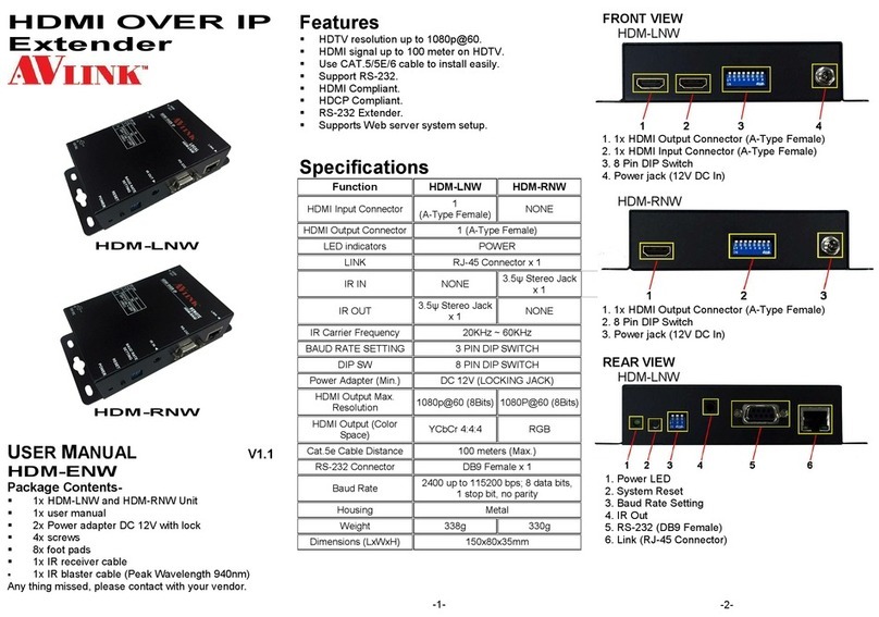
AVLink HDM-LNW User manual
AVLink
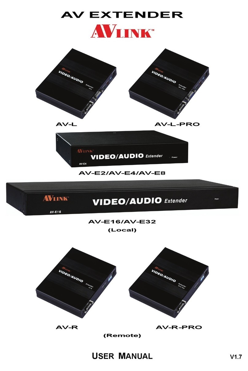
AVLink AV-L User manual
AVLink
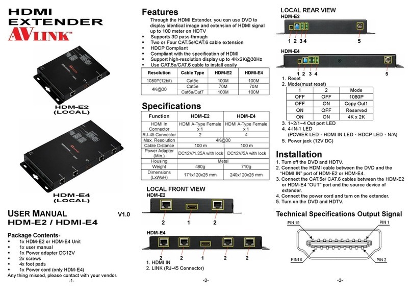
AVLink HDM-E2 User manual
AVLink
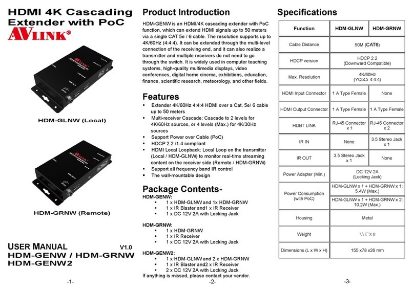
AVLink HDM-GENW User manual
AVLink
AVLink VGA-LDXW PRO User manual
AVLink
AVLink HE-A1L User manual
