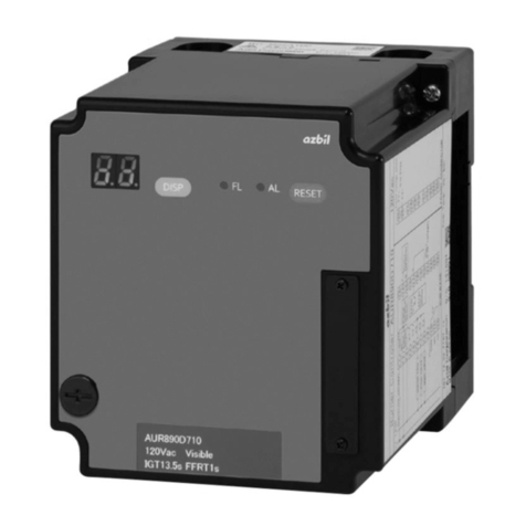
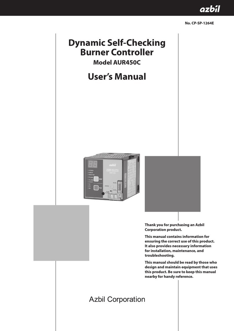
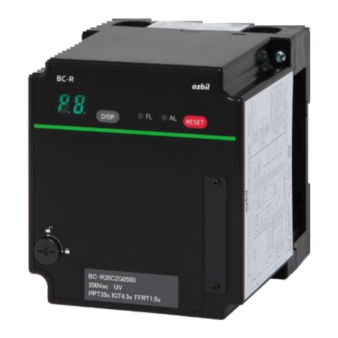
Azbil AUR890 Series User manual

1
ADD FURNACE CO.,LTD.
44 ซอยบรมราชชนนี
โทร: 02-888-3472 โทร: ออกแบบ:08-08-170-170 แฟกซ์: 02-888-3258
https://www.add-furnace.com E-mail: [email protected]
(1) Facilities that use combustion safety equipment must be designed in compliance with relevant laws, standards, safety guidelines, and the
like. If this device is used outside Japan, please observe the local laws and standards.
(2) This device monitors for failures of the relay contacts connected to combustion-related loads (IG, PV, MV). Error E09 is output if, due to
a ground fault or incorrect wiring, voltage is generated at the terminals connected to the loads even though this device is not outputting a
load. If E09 occurs after this device is installed, recheck the wiring and eliminate the cause of the error.
No. CP-SS-1892E
AUR890
Burner Controller
Overview
AUR890 burner controllers were developed to replace the
RA890, and are designed for batch operation of combus-
tion equipment (at least one start and stop in a 24-hour
period). In combination with an AUD100 series Advanced
Ultraviolet Flame Detector or a flame rod, the AUR890
automatically executes ignition, flame monitoring, and fuel
shutoff for ON/OFF-controlled gas burners or oil burners.
Features
•7-segment LED display shows the step in the combustion
sequence, alarm codes, and flame voltage.
•The presence/absence of a f lame signal or lockout is
shown by LED indicators.
•If lockout occurs due to ignition failure or flame failure,
combustion cannot restart without a manual reset.
•If there is a false flame signal during startup, the control-
ler will be locked out.
•Conducts self-diagnosis of the internal control relay cir-
cuit.
•A base unit, Q890A100, is available for use when re-
placing the RA890.
To use this Q890A base unit when replacing the RA890,
install the Q890A base unit under the sub-base
(Q270A1024) of the RA890F/G in the same mounting
holes. Then, attach the cables that were connected to the
Q270A1024 sub-base to the new base unit. The termi-
nals have the same numbers.
Precautions on equipment instrumentation

2
ADD FURNACE CO.,LTD.
44 ซอยบรมราชชนนี
โทร: 02-888-3472 โทร: ออกแบบ:08-08-170-170 แฟกซ์: 02-888-3258
https://www.add-furnace.com E-mail: [email protected]
Specifications
Item
Description
Application
Batch-operated combustion systems burning gas, oil, or gas/oil mixture
Compatible flame detector
AUD100 / 110 / 120 series UV sensor, flame rod
Sequence
Ignition wait time from
start check
3 ±0.3 s
Lock-out timing
13.5 ±1.5 s
Main burner
combustion
wait time
0.4 s
Flame response *1
AUD100/110/120 series UV sensor
Flame rod
3 ±1 s max (when flame voltage is 3 V)
1 s max, 3 ±1 s (when flame voltage is 2 V)
Reset timing
1 s or longer (main unit RESET switch or contact reset input) *2
False flame detection
time
15 s
Operation at igni- tion
failure
Lockout
Operation at flame
failure
Lockout
Electrical
specifications
Rated power
supply
100 V AC, 200 V AC (depending on the model), 50 Hz or 60 Hz
Allowable power supply
voltage
85 to 110 % of rated power supply
Power consumption
10 W or less
Dielectric strength
1500 V AC for 1 min, or 1800 V AC for 1 s
Betweeneachterminalandground(theDINrailclamp),exceptforflamedetectorconnectionterminals(terminals14,15)
Contact rating
Ignition transformer
Pilot valve
Main valve
Alarm
300 VA
200 VA
200 VA
75 VA
Insulation resistance
At least 50 MΩ, 500 V DC megger
Betweeneachterminalandground(theDINrailclamp),exceptforflamedetectorconnectionterminals(terminals14,15)
Flame detection
level
AUD100 / 110 / 120 series UV sensor
Flame rod
Flame establishment: 1.5 to 4.5 V DC
Flame-out detection: 0.2 to 0.6 V DC
Flame establishment: 1.5 to 4.5 V DC Flame-
out detection: 0.0 to 0.1 V DC
Flame voltage out- put
Recommended flame voltage: Must be stable at 2 V DC or above
Flame voltage output range: 0.2 to 4.5 V DC
Recommended flame voltage: Must be stable at 2 V DC or above
Flame voltage output range: 0.0 to 4.5 V DC
Input
Each input is a non-voltage contact input, with allowable contact resistance up to 500 Ω Low voltage temp.
controller, contact reset
Service life
10yearswhen usedfor eighthoursperday,or100,000 start/stop cycles (at 25°C,constanttemperature, rated voltage)
Transportation
and
storage
conditions
Ambient temperature
-20 to +70 °C
Ambient humidity
5 to 95 % RH (without condensation)
Vibration
0 to 9.8 m/s2 (10 to 150 Hz, 1 octave/minute, 10 cycles, in each of XYZ directions)
Shock
0 to 300 m/s2
Packaged drop test
60 cm drop height (free drop onto 1 corner, 3 edges, 6 sides)
Operating
conditions
Ambient temperature
-20 to +60 °C
Ambient humidity
10 to 90 % RH (without condensation)
Vibration
0 to 3.2 m/s2 (10 to 150 Hz, 1 octave/minute, 10 cycles, in each of XYZ directions)
Shock
0 to 9.8 m/s2
Mounting angle
Reference plane ±10°
Dust
0.3 mg/m3 or less
General
specifications
Protective structure
IP40 (with a sideboard (81447515-001) attached to the sub-base (BC-R05)) IP10 • When only
the replacement base unit (Q890A100) is used
•sub-base (BC-R05) only
Overvoltage category
II
Pollution degree
PD2
Case color
Black
Case material
Denatured PPE resin (UL94-V0 PTI materials group IIIa)
Structure
Sub-base and a main unit
Mounting orienta-
tion
Vertical or horizontal
However, in horizontal mounting the 7-segment display must face directly upward (DIN rail mounting or
direct mounting through base screw holes)
Dimensions
When used in combination with the replacement base unit (Q890A100) : W126 ×H136 ×D147 mm When used in
combination with the sub-base (BC-R05A100) : W95 ×H105 ×D110 mm
Weight
Approximately 1200g (When used in combination with the replacement base unit), Approximately 600 g (incl. sub-base)
Wiring types and max. wiring length
- Low voltage temp. controller
Copper IV wire with 600 V vinyl insulation, 1.25 mm2, recommended condition: 20 m or less, maximum wiring length: 100 m
- Contact reset
Copper IV wire with 600 V vinyl insulation, 1.25 mm2, maximum wiring length: 10 m
- AUD100 Series (F, G)
Copper IV wire with 600 V vinyl insulation, 1.25 mm2, maximum wiring length: 100 m, 2 mm2, maximum wiring length: 200 m
- Flame rod (F, G)
RG-11U (JAN standard: US DoD compliant specification) or equivalent, 5C2V, 7C2V (JIS standard)
Recommended condition: 20 m or less, maximum wiring length: 30 m
- Signal line for flame voltage output
IV wire, 0.75 mm2 or larger, max. wiring length 10 m
*1 Depending on the model.
*2 Also, reset input is not accepted if no alarm has occurred.
3
ADD FURNACE CO.,LTD.
44 ซอยบรมราชชนนี
โทร: 02-888-3472 โทร: ออกแบบ:08-08-170-170 แฟกซ์: 02-888-3258
https://www.add-furnace.com E-mail: [email protected]
Model selection guide
(Note: The dedicated sub-base and sideboard are not provided with the AUR890 series controller. Order them separately.)
Model number
Power supply
Lock-out timing
Flame response
Compatible flame detector
AUR890F110
100 V AC
13.5 ±1.5 s
1 s max. *1
Flame rod (Ionization)
AUR890F130
100 V AC
13.5 ±1.5 s
3 ±1 s *1
Flame rod (Ionization)
AUR890F210
200 V AC
13.5 ±1.5 s
1 s max. *1
Flame rod (Ionization)
AUR890F230
200 V AC
13.5 ±1.5 s
3 ±1 s *1
Flame rod (Ionization)
AUR890G130
100 V AC
13.5 ±1.5 s
3 ±1 s *2
UV sensor (AUD100/110/120)
AUR890G230
200 V AC
13.5 ±1.5 s
3 ±1 s *2
UV sensor (AUD100/110/120)
*1 At flame voltage 2 V DC
*2 At flame voltage 3 VDC
Compatible flame detector (sold separately)
UV sensor
Model number
Name
Notes
AUD15C1000
Advanced UV sensor
tube unit
Use a dedicated socket for the AUD100C/110C/120C
AUD100C100_
Dedicated socket for the AUD15
Lead wire type
AUD15C1000, sold separately
AUD100C1000-A15
AUD15C1000 in package
AUD110C100_
Dedicated socket for the AUD15
Terminal board type
AUD15C1000, sold separately
AUD110C1000-A15
AUD15C1000 in package
AUD120C120_
Dedicated socket for the AUD15
1/2-inch mounting type
Without G1/2 adapter, AUD15C1000, sold separately
AUD120C121_
With G1/2 adapter, AUD15C1000, sold separately
_: 0: standard product, D: with inspection record (with data), T: tropicalization treatment (AUD110C only), B: with inspection record (with data) +
tropicalization treatment (AUD110C only)
Flame rod
Model number
Name
Notes
C7007A
Flame rod holder
Discontinued
C7008A
Flame rod assembly
Discontinued
Options (sold separately)
Model number
Product name
Notes
BC-R05A100
Dedicated sub-base for BC-R
Required for AUR890
81447514-001
Connector for front wiring *
Contains one.
Weidmueller model number : BL3.5/11F, compatible wire: 0.2-1.5 mm2 (AWG28-14)
81447514-002
Connector for front wiring *
(For right-side wiring)
Contains one.
Weidmueller model number : BL3.5/11/270F, compatible wire: 0.2-1.5 mm2 (AWG28-14)
81447515-001
Sideboards
Contains two.
Not included in the sub-base.
Q890A100
Q890A base unit
(when replacing the RA890)
The mounting holes and terminal numbers are the same as those of the sub-base
(Q270A1024) for the RA890.
FSP136A100
Analog flame meter
81447519-001
Jack and jack cover
(Included with the controller.)
81447531-001
Front connector cover
Packaged with mounting screws (Included with the controller.)
* Used for flame voltage measurement.

4
ADD FURNACE CO.,LTD.
44 ซอยบรมราชชนนี
โทร: 02-888-3472 โทร: ออกแบบ:08-08-170-170 แฟกซ์: 02-888-3258
https://www.add-furnace.com E-mail: [email protected]
Terminal numbers, front panel item names
Front
Display
RESET switch
DISP switch
BC-R05A100 Sub-base (sold separately)
Front connector cover
(connector is behind
cover)
Loader jack *
* Not used
DIN rail clamp Terminal board
(for inspection and adjustment before shipment)
Terminal numbers
Front connector terminals BC-R05A100 Sub-base terminals
Connector for front wiring
(81447514-001) terminal layout
Connector for front wiring (for right side wiring)
(81447514-002) terminal layout
Mounting screw Mounting screw
25
Wiring fastener
screw
Wiring
Wiring fastener
screw
Wiring
35
Mounting screw
Mounting screw
25
35
No.
Function
No.
Function
25
Flame voltage output (+)
31
NC
26
Flame voltage output (-)
32
NC
27
NC
33
NC
28
NC
34
NC
29
NC
35
NC
30
NC
-
-
No.
Function
No.
Function
1
Line voltage temp. controller
14
Flame detector (F)
2
AC power supply (L1)
15
Flame detector (G)
3
AC power supply (L2 (N))
16
NC
4
NC
17
Input common
5
NC
18
NC
6
Ignition transformer output
19
NC
7
Pilot valve output
20
Low voltage temp. control-
ler
Non-voltage contacts
(betw. 17 and 20)
8
Main valve output
9
NC
10
Alarm output COM
21
NC
11
Alarm output NO
22
NC
12
Alarm output NC
23
NC
13
NC
24
Contact reset

5
ADD FURNACE CO.,LTD.
44 ซอยบรมราชชนนี
โทร: 02-888-3472 โทร: ออกแบบ:08-08-170-170 แฟกซ์: 02-888-3258
https://www.add-furnace.com E-mail: [email protected]
6
T
5
T
4
F
3
G
1
COM
2
NO
NC
External connection terminals of the RA890 replacement base unit (Q890A100)
External connection terminals of Q890A100
When the upper part of the replacement base unit is removed,
the external connection terminals can be viewed.
Q590A100 external-connection
terminal Nos.
No.
Function
1
AC power supply (L1)
2
AC power supply (L2 (N))
3
Pilot valve output
4
Ignition transformer output
5
Main valve output
6
Line voltage temp. controller
T
External controller (for low voltage)
(Non-voltage contacts)
T
F
Flame detector
G
COM
Alarm output
NO
NC
Q890A100

6
ADD FURNACE CO.,LTD.
44 ซอยบรมราชชนนี
โทร: 02-888-3472 โทร: ออกแบบ:08-08-170-170 แฟกซ์: 02-888-3258
https://www.add-furnace.com E-mail: [email protected]
External dimensions
AUR890 with the BC-R05A100 sub-base
AUR890 Burner Controller
61
(Unit: mm)
Sub-base (sold separately)
AUR890 main unit
fastening screw
Model number
A
81447514-001
10.6
81447514-002
14.6
Sub-base BC-R05A100 (sold separately)
95
110
Connector for
front wiring
Sub-base
(sold separately)
AUR890 main unit
fastening screw
A
DIN rail clamp
64
M3.5 (terminal screw)
12 øknockout hole
12 øknockout hole
Sub-base
mounting hole
Sub-base
mounting hole
95
62.5
DIN rail clamp
61
Knockout hole
16
Knockout hole
27
17
105
27
17
105

7
ADD FURNACE CO.,LTD.
44 ซอยบรมราชชนนี
โทร: 02-888-3472 โทร: ออกแบบ:08-08-170-170 แฟกซ์: 02-888-3258
https://www.add-furnace.com E-mail: [email protected]
AUR890
Main unit
Sideboard 81447515-001 (sold separately)
Installation orientation
Install the device in the orientation shown below.
(Unit: mm)
Correct Correct
Do not install it in the orientations illustrated below.
Incorrect
Mounting in a panel
[1] Drill two M4 screw holes into the panel.
[2] Use screws to mount the sub-base on the panel.
(Maximum tightening torque: 1.2 N·m)
(Unit: mm)
30.7
Sub-base
Sub-base
19 øknockout hole
Sideboard
Sideboard
19 øknockout hole
23.9
Display area
AUR890
Main unit
AUR890
Main unit
M4
62.5 (2 locations)
46.6
73.5

8
ADD FURNACE CO.,LTD.
44 ซอยบรมราชชนนี
โทร: 02-888-3472 โทร: ออกแบบ:08-08-170-170 แฟกซ์: 02-888-3258
https://www.add-furnace.com E-mail: [email protected]
Screw (4) securing the upper part
of the replacement base unit
23 øhole (4 places)
M4 ground screw
25.5
31
Grommet (4 places)
9.5
Q890A100 base unit for RA890-AUR890 replacement
AUR890 Burner Controller
(Unit: mm)
Model number
A
81447514-001
10.6
81447514-002
14.6
126
147
AUR890 main unit
fastening screw
Connector for
front wiring
AUR890 main unit fastening screw
A
Sideboard (in package)
Screw (4) securing the upper part
of the replacement base unit
37
5
126
5
19

9
ADD FURNACE CO.,LTD.
44 ซอยบรมราชชนนี
โทร: 02-888-3472 โทร: ออกแบบ:08-08-170-170 แฟกซ์: 02-888-3258
https://www.add-furnace.com E-mail: [email protected]
Q890A100 base unit for RA890-AUR890 replacement (sold separately)
Installation orientation
Install the device in the orientation shown below.
(Unit: mm)
Display area Correct AUR890
Main unit Correct
Do not install it in the orientations illustrated below.
Incorrect
126
70
Sideboard (in package)
M4 ground screw
23 øhole (4 places)
25.5 31
Grommet (4 places)
9.5
AUR890
Main unit
AUR890
Main unit
37
5
126
5
19

10
ADD FURNACE CO.,LTD.
44 ซอยบรมราชชนนี
โทร: 02-888-3472 โทร: ออกแบบ:08-08-170-170 แฟกซ์: 02-888-3258
https://www.add-furnace.com E-mail: [email protected]
5.5 ømounting hole (3 places)
Mounting in a panel
[1] Drill three 5 screw holes into the panel.
[2] Loosen the four retaining screws to remove the upper part of the replacement base unit.
[3] Insert screws into the three mounting holes on the lower part of the base unit, and tighten the screws.
(Unit: mm)
[4] Wire the external connections to the terminal block on the lower part of the replacement base unit, and then connect
the cable connectors of the upper part of the base unit to the connectors on the lower part.
[5] After connecting the connectors, secure the upper part to the lower part using the four retaining screws. (maximum
tightening torque: 1.2 N·m)
Structure of the replacement base unit (Q890A100)
(Upper part of Q890)
(Lower part of Q890)
73
104.8
(3 places)
Screw (4) securing the upper part
of the replacement base unit
Screw (4) securing the upper part
of the replacement base unit

11
ADD FURNACE CO.,LTD.
44 ซอยบรมราชชนนี
โทร: 02-888-3472 โทร: ออกแบบ:08-08-170-170 แฟกซ์: 02-888-3258
https://www.add-furnace.com E-mail: [email protected]
7-segment display, LED display, switches
If this device detects a flame failure etc., it isolates the load and applies a lockout. During lockout, the relevant diagnostic
function code is displayed on the 7-segment display.
Part name
7-segment LED (green)
When normal:
sequence code/ flame voltage
When an error occurs:
Alarm code/ flame voltage
DISP switch
Flame voltage/ sequence code
Flame voltage/ alarm code display switch
Flame LED (green)
Lit when flame signal is detected.
Off when flame signal is off.
Jack *
* Not used
(for adjustment before shipment)
AUR890 main unit fastening screw
RESET switch
Switch to cancel lockout
(Press and hold for approximately 1s)
ALARM LED (red)
Lit duringlockout.
Off when there is no lockout.
Front connector
Flame voltage output (0-5V)
Identification label
Alarm codes
Alarm
codes
Sub-code
Description
1
None
False flame
Ignition failure
7
Flame failure
Switch input
Internal relay feedback (K1)
Terminal 7 voltage discrepancy (PV)
Terminal 8 voltage discrepancy (MV)
7
Terminal 6 voltage discrepancy (IG)
8
Alarm activation at power ON
or more
Device error
Sequence codes
Display
Status content
P 1
Start check
Ignition standby
P
Lock-out timing
Main burner combustion standby
P8
RUN
--
Stop
Examples of sequence codes and alarm codes
•Alarm code: E1 to E7 • Alarm code: E9 + sub-code (2 digits)
Switches every 0.8 s Switches every 0.8 s
(sub-code)

12
ADD FURNACE CO.,LTD.
44 ซอยบรมราชชนนี
โทร: 02-888-3472 โทร: ออกแบบ:08-08-170-170 แฟกซ์: 02-888-3258
https://www.add-furnace.com E-mail: [email protected]
Terminal layout
of connector
for front wiring
Internal block circuit, external connection terminals
With the sub-base BC-R05A100 (1-24 on sub-base, 25-35 on front connector)
•Non-recycling gas-fired combustion
L1 L2(N)
* Use the external controller for either the power supply or for low voltage.
If the line voltage controller is used to start burner controller operation,
connect terminal 17 to terminal 20.
Breaker
Burner on-off circuit
Limit / Interlock Circuit
Bloweroperationcircuit/prepurgecircuit
Prepurge completion signal
Line voltage temp. *
controller
AUR890/BC-R05A100
10 A
1 AC input
circuit NC 13
2
Power
supply circuit
Flame
detection
Circuit
14
F
Flame
3
4 NC
K1
15
G detector
24 V DC
K2
TM1
Ignition transformer
5 NC
6 K5
TM1
Pilot valve 1
7
K3
NC 16
17 +
NC 18
Input NC 19 Low voltage temp.
circuit controller*
(24V DC) 20
Pilot valve 2
103X
NC 21
TM
1TM1
Main valve 1
NC 22
8
K4
NC 23
Contact reset
Main valve 2
24
103
X
9 NC
10
Alarm outputCOM
Alarm
11
12
Alarm outputNO
K6
Alarm outputNC
Flame
voltage
circuit
25
26
NC 27
FV+ 0 to 5 V DC
FV-
NC 35
RESET
Switch
DISP
Switch
Display
FLAME
ALARM
Combustion
safety
control
circuit

13
ADD FURNACE CO.,LTD.
44 ซอยบรมราชชนนี
โทร: 02-888-3472 โทร: ออกแบบ:08-08-170-170 แฟกซ์: 02-888-3258
https://www.add-furnace.com E-mail: [email protected]
for front wiring
•Non-recycling oil-fired combustion (2-level combustion)
L1 L2(N)
Terminal layout
of connector
* Use the external controller for either the power supply or for low voltage.
If the line voltage controller is used to start burner controller operation,
connect terminal 17 to terminal 20.
Breaker
Burner on-off circuit
Limit / Interlock circuit
Bloweroperationcircuit/prepurgecircuit
Prepurge completion signal
Line voltage temp. *
controller
AUR890/BC-R05A100
10A
1
AC input
circuit
NC 13
2
Power
supply circuit
Flame
detection
circuit
14
F
Flame
K1
15
G detector
Ignition transformer
3
4 NC
5 NC
6
24 V DC
K2
K5
Fuel oil valve
Two-level fuel oil valve
7
K3
Input
circuit
(24 V DC)
NC 16
17 +
NC 18
NC 19 Low voltage temp. *
controller
20
Alarm
8K4
9 NC
10 Alarm outputCOM
11 Alarm output NO K6
Combustion
safety
control
circuit
12
Alarm outputNC
NC 21
NC 22
NC 23 Contact reset
24
Flame
voltage
circuit
25
26
NC 27
FV+ 0 to 5 V DC
FV-
NC 35
RESET
switch
DISP
switch
Display
FLAME
ALARM

14
ADD FURNACE CO.,LTD.
44 ซอยบรมราชชนนี
โทร: 02-888-3472 โทร: ออกแบบ:08-08-170-170 แฟกซ์: 02-888-3258
https://www.add-furnace.com E-mail: [email protected]
Q890A100 base unit for RA890-AUR890 replacement
•Non-recycling gas-fired combustion
L2(N) L1
Breaker
* Use the external controller for either the power supply or for low voltage.
If the line voltage controller is used to start burner controller operation,
connect terminal 17 to terminal 20.
Burner on-off circuit
Limit / Interlock Circuit
Blower operation circuit / prepurge circuit
Line voltage temp. controller * Prepurge completion signal
Terminal numbers of Q890A100 base unit (for RA890 replacement)
AUR890/BC-R05A100
10 A
RESET Display
switch
DISP
switch
6
1
K4
FLAME
ALARM
8
5
103
X
TM1 Main valve 1
Main valve2
DC 24 V
K5
TM1
T
+ 17
6
4
Ignition transformer
Low voltage temp. *
controller
Input
circuit
(24 V DC)
K3
TM1
T 20 7 3 Pilot valve 1
103X
Pilot valve 2
K2
F
F
14
TM
1
AC input
circuit
K1
2
1
Flame
detection
circuit
Power
supply circuit
G
G
15
3
2
Flame voltage
circuit
K6
FV+ FV-
25 26
Alarm
Alarm
10 11
Alarm
12
output COM output NO output NC
COM
NO
NC
Alarm
: Terminal numbers of AUR890/BC-R05
: Terminal numbers of Q890A100 base unit
(for RA890 replacement)
: Terminal numbers of the front connector
Terminal layout
of connector
for front wiring
Flame
detector
Combustion
safety
control
circuit

15
ADD FURNACE CO.,LTD.
44 ซอยบรมราชชนนี
โทร: 02-888-3472 โทร: ออกแบบ:08-08-170-170 แฟกซ์: 02-888-3258
https://www.add-furnace.com E-mail: [email protected]
for front wiring
•Non-recycling oil-fired combustion (2-level combustion)
L2(N) L1
Breaker
Burner on-off circuit Limit / Interlock Circuit
Blower operation circuit / prepurge circuit
Line voltage temp. controller * Prepurge completion signal
Terminal numbers of Q890A100 base unit (for RA890 replacement)
AUR890/BC-R05A100
10 A
6 1
RESET
switch
Display
FLAME
ALARM
DISP
switch K4 8
5 Two-level fuel oil valve
T + 17
Input
DC 24 V
K5 6 4 Ignition transformer
Low voltage temp. *
controller T
F
G
20
F 14
G 15
circuit
(24V DC)
Flame
detection
circuit
AC input
circuit
K3 7
K2
K1 2
Power
supply circuit
3
3 Fuel oilvalve
1
2
FV+
Flame voltage
circuit K6
FV-
25 26
Alarm
10
Alarm
11 12
Alarm
output COM
output NO
output NC
COM
NO NC
Alarm
: Terminal numbers of AUR890/BC-R05 Terminal layout
of connector
: Terminal numbers of Q890A100 base unit
(for RA890 replacement)
: Terminal numbers of the front connector
* Use the external controller for either the power supply or for low voltage.
If the line voltage controller is used to start burner controller operation,
connect terminal 17 to terminal 20.
Flame
detector
Combustion
safety
control
circuit

16
ADD FURNACE CO.,LTD.
44 ซอยบรมราชชนนี
โทร: 02-888-3472 โทร: ออกแบบ:08-08-170-170 แฟกซ์: 02-888-3258
https://www.add-furnace.com E-mail: [email protected]
Operation sequence
Normal operation (Non-recycling gas-fired combustion)
[7-segment display]
[Input]
Power supply
–– ––
P1 P3
P4 P5 P8 ––
Limit, Interlock
Burner operation switch
Blower
Controller
Flame signal
AUR890
RESET switch
[Output]
Ignition transformer
Pilot valve
TM1 on delay time
Main valve
Alarm output
[LED]
FLAME LED (Green)
ALARM LED (Red)
Approximately 8 s
Pre-purge time
(external circuit)
Main burner combustion standby time
Lock-out timing time
Start check + Ignition standby time
Approximately 3 s
Input
AUR890 operation
Sequence
codes
Operation of external devices
Power-ON
When eight seconds have passed after the power has been turned on,
the 7-segment LED display on the front panel of the AUR890 shows the
sequence code [––].
––
Burner
operation
switch ON
––
When the burner operation switch is turned
on, the blower starts operation, and a
prepurge is done if the limit and interlock
conditions are normal. When the prepurge is
complete, the prepurge completion signal is
turned ON.
Blower: ON
Controller:
ON
If the prepurge completion signal is ON and the controller is ON, the
internal circuits are checked during the start check.
P 1
Afterward a false flame check is conducted during the ignition wait
time.
If the status is normal, lockout time begins, relays K1, K2, K3, and K5
turn ON, the ignition transformer starts, the pilot valve begins to open,
and external timer TM1 turns ON.
Ignition transformer : start
Pilot valve : open
(TM1 starts)
When the flame detector detects the pilot burner flame, relay K5 turns
OFF to stop the ignition transformer.
Ignition transformer : continues operation
Pilot valve : remains open
Relay 4K and external relay 103X turn ON.
When the time set for TM1 operation has passed and TM1's contacts
have turned on, the main valves open to begin normal combustion.
FLAME LED (green) on the front panel of the AUR890 turns on.
P8
Ignition transformer : stop
Main valve : open
(103X : ON)
(TM1's contacts : ON)
Burner
operation
switch OFF
When the burner operation switch turns OFF, relays K1, K2, K3, and K4
turn OFF, and the pilot and main valves begin to close.
FLAME LED (green) on the front panel of the AUR890 turns off.
––
Fuel oil combustion valve : closed
Main valve : closed
Blower : stop
Power-OFF
When the power is turned OFF, the 7-segment LED display on the front
panel of the AUR890 stops showing the sequence code [––].
* The AUR890 turns the main valve ON after the standby process for normal combustion. This feature does not allow the main valve to be turned on immediately after ignition in order to prevent the flame from being blown out. During the standby
process for normal combustion, if the time set for external timer TM1 is complete and the contacts are reversed, the supply of power to the pilot valve and main valve may be interrupted for a moment.
Whenever a flame is detected just before completion of the time set for external timer TM1, ignition is delayed. Adjust the burner so that it ignites
reliably at least one second before the time set for external timer TM1 passes.

17
ADD FURNACE CO.,LTD.
44 ซอยบรมราชชนนี
โทร: 02-888-3472 โทร: ออกแบบ:08-08-170-170 แฟกซ์: 02-888-3258
https://www.add-furnace.com E-mail: [email protected]
Normal operation (Non-recycling oil-fired combustion (2-level combustion))
[7-segment display]
[Input]
Power supply
–– ––
P1 P3
P4 P5 P8 ––
Limit, Interlock
Burner operation switch
Blower
Controller
Combustion signal
AUR890
Reset switch
[Output]
Ignition transformer
Fuel oil valve
Two-level fuel oil valve
Warning output
[LED]
FLAME LED (Green)
ALARM LED (Red)
Approximately 8 s Pre-purge time
(external circuit)
Main burner combustion standby time
Lock-out timing time
Start check + Ignition standby time
Input
AUR890 operation
Sequence
codes
Operation of external devices
Power-ON
When eight seconds have passed after the power has been turned on,
the 7-segment LED display on the front panel of the AUR890 shows the
sequence code [––].
––
Burner
operation
switch ON
––
When the burner operation switch is turned
on, the blower starts operation, and a
prepurge is done if the limit and interlock
conditions are normal. When the prepurge is
complete, the prepurge completion signal is
turned ON.
Blower: ON
External
controller:
ON
If the prepurge completion signal is ON and the external controller is
ON, the internal circuits are checked during the start check.
P 1
Afterward a false flame check is conducted during the ignition wait time.
In normal operation, safety lockout timing begins, relays K1, K2, K3, and
K5 turn ON, the ignition transformer starts, and the fuel oil valve opens.
Ignition transformer : start
Fuel oil valve : open
After the lockout time has passed, if a flame signal is detected,
the ignition transformer output is maintained until the main burner
combustion standby time has passed.
Ignition transformer : continues operation
Fuel oil valve : remains open
When the flame sensor detects the flame from the fuel oil valve, relay
K5 turns OFF, the ignition transformer stops, relay K4 turns ON, and the
two-level fuel oil valve opens, starting main burner combustion.
FLAME LED (green) on the front panel of the AUR890 turns on.
P8
Ignition transformer : stop
Two-level fuel oil valve : open
Burner
operation
switch OFF
When the burner operation switch is turned OFF, relays K1, K2, K3, and
K4 turn OFF, and the fuel oil valve and two-level fuel oil valve close.
FLAME LED (green) on the front panel of the AUR890 turns off.
––
Fuel oil valve : closed
Two-level fuel oil valve : closed
Blower : stop
Power-OFF
When the power is turned OFF, the 7-segment LED display on the front
panel of the AUR890 stops showing the sequence code [––].

ADD FURNACE CO.,LTD.
44 ซอยบรมราชชนนี
โทร: 02-888-3472 โทร: ออกแบบ:08-08-170-170 แฟกซ์: 02-888-3258
https://www.add-furnace.com E-mail: [email protected]
Specifications are subject to change without notice.
1-12-2 Kawana, Fujisawa
Kanagawa 251-8522 Japan
http://www.azbil.com/
(13)
1st edition: Jan. 2015
3rd edition: July 2018
No part of this publication may be reproduced or duplicated
without the prior written permission of Azbil Corporation.
Please read “Terms and Conditions” from the following URL
before ordering and use.
http://www.azbil.com/products/factory/order.html
20
Other manuals for AUR890 Series
2
Table of contents
Other Azbil Controllers manuals

Azbil
Azbil AUR890 Series User manual

Azbil
Azbil C26 User manual

Azbil
Azbil F4Q User manual

Azbil
Azbil RA890G User manual

Azbil
Azbil Infilex BC WY5610 User manual

Azbil
Azbil BC-R35 Series User manual

Azbil
Azbil C15 User manual

Azbil
Azbil INFILEX GC WY5311 User manual

Azbil
Azbil Infilex VC User manual

Azbil
Azbil C35 User manual
Popular Controllers manuals by other brands

Full Gauge Controls
Full Gauge Controls MT-530 Super manual

McQuay
McQuay MicroTech III Installation and maintenance manual

Delem
Delem DA-52s Reference manual

Hanna Instruments
Hanna Instruments BL 983320-0 user manual

Disaster Area Designs
Disaster Area Designs DMC.micro user manual

YASKAWA
YASKAWA PROFINET 1000 Series Technical manual