J1
CP-UM-5445JE
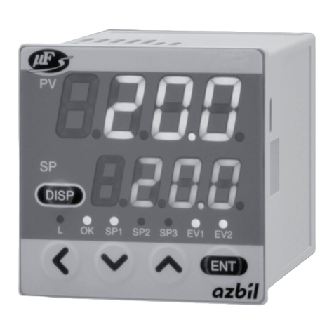
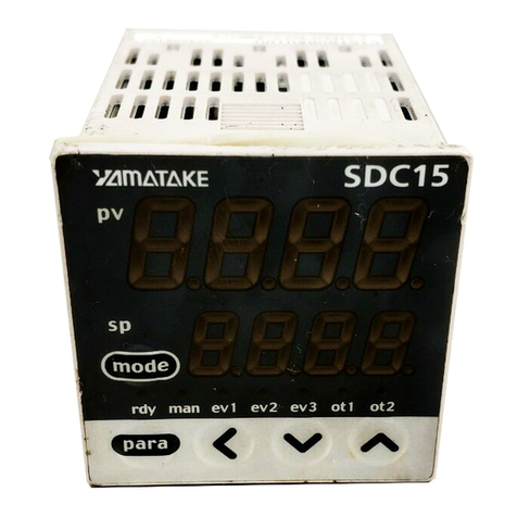
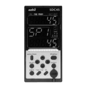
デジタル指示調節計
形 C45/46
取扱説明書 設置編
このたびは当社製品をご購入いただき、まことにありがとうございます。
この取扱説明書には、製品を安全に正しくご使用いただくための必要
事項が記載されております。また、この取扱説明書は、取り付け時だ
けでなく、保守、トラブル時の対応などの際に必要です。当社製品を
使用した操作盤、装置の設計、保守を担当される方は、必ずお読みに
なり、理解したうえでご使用ください。いつもお手元においてご活用
ください。
ご注文・ご使用に際しては、下記URLより「ご注文・ご使用に際して
のご承諾事項」を必ずお読みください。
https://www.azbil.com/jp/product/factory/order.html
お願い
この取扱説明書は、本製品をお使いになる担当者のお手元に確実に届
くようにお取りはからいください。
この取扱説明書の全部、または一部を無断で複写、または転載するこ
とを禁じます。この取扱説明書の内容を将来予告なしに変更すること
があります。
この取扱説明書の内容については、万全を期しておりますが、万一ご
不審な点や記入もれなどがありましたら、当社までご連絡ください。
お客さまが運用された結果につきましては、責任を負いかねる場合が
ございますので、ご了承ください。
関連取扱説明書
本書は使用上の注意事項と取り付け・結線・PVレンジ種類・おもな仕
様などを説明したものです。詳しい取扱方法・設定方法などは、別冊の「詳
細編」および「表示・設定データ一覧」をご覧ください。
各種機能の操作については次の説明書があります。
必要に応じてお読みください。
・ デジタル指示調節計 形C45/C46 表示・設定データ一覧
CP-UM-5457
・ デジタル指示調節計形C45/C46 取扱説明書 詳細編
CP-SP-1218
・ デジタル指示調節計 形C45V/46V 取扱説明書 演算機能編
CP-SP-1275
・ デジタル指示調節計形C45/46 用 スマートローダパッ
ケージ形SLP-C45取扱説明書 CP-UM-5458
これらの資料はhttps://www.compoclub.comからダウンロードする
こともできます。
確認してください
お買い上げいただいたSDC45/46は次のものが同梱されています。
万一、異常や間違いがあった場合は、直ちにお買い上げの販売店までご
連絡ください。
・ 取付器具 81405411-004 2個
・ ガスケット(形C45用) 81421863-001 1個
(形C46用) 81421864-001 1個
・ 取扱説明書(本書) CP-UM-5445JE 1部
・ 表示・設定データ一覧 CP-UM-5457 1部
安全要求事項(SAFETY REQUIREMENT)
人に損傷を与えるような感電の危険を減ずるために、この取扱説明書
に記載されているすべての安全に関わる注意事項に従ってください。
このシンボルは、触ると感電のおそれがあることをお客さまに警告す
るものです。
•当社が規定しない使い方をした場合、この製品に盛り込まれた安全保
護は損なわれます。
•当社によって決められた以外の部品に交換しないでください。
•すべての配線作業は、それぞれの地域での規則に従って、認定されか
つ経験のある作業者によって行われなければなりません。
•本器を操作される方がとどく範囲内に、本器の主電源遮断用のスイッ
チを必ず設けてください。
•AC電源モデルの主電源配線には、遅動タイプ(T)の、定格電流 1.0A、
定格電圧250Vのヒューズを設けてください。ヒューズは非接地側の
配線に設けてください。(IEC127)
•DC電源モデルの主電源に接続するDC電源装置には、クラスⅡの電
源装置を使用してください。
●機器の定格
AC電源モデル
供給電圧 AC100 ~240V(動作電源電圧AC85~264V)
電源周波数 50/60Hz
消費電力 30VA以下(SDC45)、40VA 以下(SDC46)
DC電源モデル
供給電圧 DC24V(動作電源電圧 DC21.6 ~ 26.4V)
消費電力 12W以下(SDC45)、15W 以下(SDC46)
●環境条件
可燃性の液体や蒸気のある場所では使用しないでください。
そのような環境下で使用すると安全性を損ないます。
使用温度範囲 0 ~ 50℃
使用湿度範囲 10 ~ 90%RH(結露なきこと)
許容振動 2m/s2
(10 ~ 60Hz)
過電圧カテゴリ CategoryⅡ(IEC60364-4-443、IEC60664-1)
汚染度 Pollutiondegree2
設置場所 屋 内
高 度 2000m以下
一時的過電圧 電源電圧+250V
●機器の設置
本器を操作される方が本器の背面端子に触らないように、本器は必
ずパネルに取り付けてください。供給電源およびリレー接点出力を
除く入出力のコモンモード電圧:対大地間の電圧は、
30Vrms以下、42.4V ピーク以下、DC60V 以下としてください。
●適合規格
EN61010-1、EN61326-1(Foruseinindustriallocations)
EMC試験中、± 10%FS に相当する指示値や出力値の変動が生じ
る場合があります。
安全上の注意
この安全上の注意は、製品を安全に正しくお使いいただき、あなたや他
の人々への危害や財産への損害を未然に防止するためのものです。安全
上の注意は必ず守ってください。また、内容をよく理解してから本文を
お読みください。
● 警告表示の意味
警告 取り扱いを誤った場合に、使用者が死亡または重傷
を負う危険の状態が生じることが想定される場合。
注意 取り扱いを誤った場合に、使用者が軽傷を負うか、
または物的損害のみが発生する危険の状態が生じる
ことが想定される場合。
警告
導電性の汚染が生ずる環境、もしくは結露などによって導電性とな
る乾燥した非導電性の汚染が生ずる環境で使用しないでください。
トラッキング現象などによる部品故障や、その部品故障に起因する
火災を引き起こすおそれがあります。
本器の電源配線には仕様に記載されているヒューズを設けてくださ
い。トラッキング現象に起因する火災や、他要因による部品故障に
起因する火災のおそれがあります。
FG端子を D 種接地以上に確実に接続してから、測定対象や外部制御
回路への接続を行ってください。
本器への通電前に配線が正しく行われていることを確認してくださ
い。本器への配線間違いは故障の原因になり、また危険な災害を招
く原因にもなります。
本器の取り付け、取り外し、および結線のときは、本器および接続
機器の電源をすべて切ってください。
感電することがあります。
電源端子などの充電部には触らないでください。
感電のおそれがあります。
本器を分解しないでください。
感電・故障のおそれがあります。
注意
本器は、 仕様に記載された使用条件(温度、湿度、電圧、振動、衝撃、
取付方向、雰囲気など)の範囲内で使用してください。
火災、故障のおそれがあります。
本器への結線は定められた基準に従い、指定された電源、および施
工方法で正しく配線してください。
火災、感電、故障のおそれがあります。
本器ケース内部に線くず、切粉、水などが入らないようにしてくだ
さい。火災、故障のおそれがあります。
端子ねじは仕様に記載されたトルクで確実に締め付けてください。
締め付けが不完全だと火災、感電のおそれがあります。
