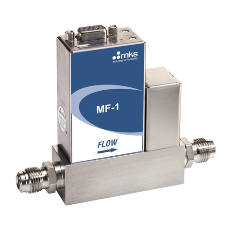
MKS 1152C User manual

-~
ARTISAN
®
~I
TECHNOLOGY
GROUP
Your definitive source
for
quality
pre-owned
equipment.
Artisan Technology
Group
Full-service,
independent
repair
center
with
experienced
engineers
and
technicians
on staff.
We
buy
your
excess,
underutilized,
and
idle
equipment
along
with
credit
for
buybacks
and
trade-ins
.
Custom
engineering
so
your
equipment
works
exactly as
you
specify.
•
Critical
and
expedited
services
•
Leasing
/
Rentals/
Demos
• In
stock/
Ready-to-ship
•
!TAR-certified
secure
asset
solutions
Expert
team
ITrust
guarantee
I
100%
satisfaction
All
tr
ademarks,
br
a
nd
names, a
nd
br
a
nd
s a
pp
earing here
in
are
th
e property of
th
e
ir
r
es
pecti
ve
ow
ner
s.
Find the MKS Instruments 1152C-731K at our website: Click HERE

112802-P1
Rev C, 4/97
Instruction Manual
MKS Type 1152C
Mass Flow Controller
Six Shattuck Road
Andover, MA 01810-2449
(800) 227-8766 or (978) 975-2350
Fax: (978) 975-0093
E-mail: mks@mksinst.com
Web site: http://www.mksinst.com
Artisan Technology Group - Quality Instrumentation ... Guaranteed | (888) 88-SOURCE | www.artisantg.com


WARRANTY
T
y
pe 1152C E
q
uipment
MKS Instruments, Inc. (MKS) warrants that the equipment described above (th
e
“equipment”) manufactured by MKS shall be free from defects in materials and
workmanship for a period of one year from date of shipment and will for a period of tw
o
years from the date of shipment, correctly perform all date-related operations, including
without limitation accepting data entry, sequencing, sorting, comparing, and reporting,
regardless of the date the operation is performed or the date involved in the operation,
provided that, if the equipment exchanges data or is otherwise used with equipment,
software, or other products of others, such products of others themselves correctl
y
perform all date-related operations and store and transmit dates and date-related dat
a
in a format compatible with MKS equipment. THIS WARRANTY IS MKS’ SOLE
WARRANTY CONCERNING DATE-RELATED OPERATIONS.
For the period commencing with the date of shipment of this equipment and ending one
year later in the case of defects in materials and workmanship, but two years later in the
case of failure to comply with the date-related operations warranty, MKS will, at its
option, either repair or replace any part which is defective in materials or workmanship
or with respect to the date-related operations warranty without charge to the purchaser.
The foregoing shall constitute the exclusive and sole remedy of the purchaser for an
y
breach by MKS of this warranty.
The purchaser, before returning any equipment covered by this warranty, which is
asserted to be defective by the purchaser, shall make specific written arrangements
with respect to the responsibility for shipping the equipment and handling any othe
r
incidental charges with the MKS sales representative or distributor from which the
equipment was purchased or, in the case of a direct purchase from MKS, with the MKS
home office in Andover, Massachusetts, USA.
This warranty does not apply to any equipment which has not been installed and used
in accordance with the specifications recommended by MKS for the proper and normal
use of the equipment. MKS shall not be liable under any circumstances for indirect,
special, consequential, or incidental damages in connection with, or arising out of, th
e
sale, performance, or use of the equipment covered by this warranty.
MKS recommends that all MKS pressure and flow products be calibrated periodicall
y
(typically every 6 to 12 months) to ensure accurate readings. When a product is
returned to MKS for this periodic re-calibration it is considered normal preventativ
e
maintenance not covered by any warranty.
THIS WARRANTY IS IN LIEU OF ALL OTHER RELEVANT WARRANTIES,
EXPRESSED OR IMPLIED, INCLUDING THE IMPLIED WARRANTY OF
MERCHANTABILITY AND THE IMPLIED WARRANTY OF FITNESS FOR
A
PARTICULAR PURPOSE, AND ANY WARRANTY AGAINST INFRINGEMENT O
F
ANY PATENT.
11-98 112802-P1
Artisan Technology Group - Quality Instrumentation ... Guaranteed | (888) 88-SOURCE | www.artisantg.com

112802-P1
Rev C, 4/97
MKS Type 1152C
Mass Flow Controller
Artisan Technology Group - Quality Instrumentation ... Guaranteed | (888) 88-SOURCE | www.artisantg.com

Copyright © 1997 by MKS Instruments, Inc.
All rights reserved. No part of this work may be reproduced or transmitted in any form or by
any means, electronic or mechanical, including photocopying and recording, or by any
information storage or retrieval system, except as may be expressly permitted in writing by MKS
Instruments, Inc.
Baratronis a registered trademark of MKS Instruments, Inc., Andover, MA
Inconelis a registered trademark of Inco Alloys International, Inc., Huntington, WV
Vitonand Kalrezare registered trademarks of E.I. DuPont de Nemours Co. Inc., Wilmington,
DE
Cajonand VCRare registered trademarks of Cajon Co., Macedonia, OH
Chemrazis a registered trademark of Greene, Tweed, & Co. Inc., Kulpsville, PA
NUPROis a registered trademark of NUPRO Co., Willoughby, OH
Artisan Technology Group - Quality Instrumentation ... Guaranteed | (888) 88-SOURCE | www.artisantg.com

Table of Contents
iii
Table of Contents
Safety Procedures and Precautions.......................................................................................... 1
Chapter One: General Information......................................................................................... 3
Introduction............................................................................................................... 3
How This Manual is Organized.................................................................................. 4
Customer Support...................................................................................................... 4
Chapter Two: Installation......................................................................................................5
How To Unpack the Type 1152 Unit.......................................................................... 5
Unpacking Checklist ..................................................................................... 5
Interface Cables ......................................................................................................... 6
Standard Cables............................................................................................. 6
Generic Shielded Cable Description .............................................................. 7
Product Location and Requirements........................................................................... 9
Operating Environmental Requirements ........................................................ 9
Setup ......................................................................................................................... 9
Dimensions................................................................................................... 9
Mounting ...................................................................................................... 11
Mechanical Installation.................................................................................. 12
Electrical Information................................................................................................ 14
Power Requirements...................................................................................... 14
Connectors.................................................................................................... 14
Chapter Three: Overview....................................................................................................... 17
General Information................................................................................................... 17
System Operating Temperature...................................................................... 17
Changing the Range of the 1152 Unit ........................................................................ 17
Calibration................................................................................................................. 18
Label ......................................................................................................................... 18
Analog Interface Signals............................................................................................ 19
Chapter Four: Operation........................................................................................................21
Artisan Technology Group - Quality Instrumentation ... Guaranteed | (888) 88-SOURCE | www.artisantg.com

Table of Contents
iv
How To Set the Temperature......................................................................................21
Temperature Indications.................................................................................23
Temperature Output Signal............................................................................23
How To Warm Up the 1152 MFC ..............................................................................24
How To Zero the 1152 MFC ......................................................................................25
How To Configure the Output....................................................................................26
To Display the Output in SCCM....................................................................26
Cautionary Notes........................................................................................................28
Note 1: Customer Supplied Display Equipment ............................................28
Note 2: MKS Supplied Power Supply/Display Equipment............................28
Note 3: Set Point Command..........................................................................28
Note 4: Overrange Condition........................................................................28
Chapter Five: Troubleshooting...............................................................................................29
General Information ...................................................................................................29
Troubleshooting Chart ...................................................................................29
How To Check Valve Operation....................................................................31
How To Prevent Oscillation...........................................................................31
Chapter Six: Maintenance......................................................................................................33
General Information ...................................................................................................33
Cleaning and Repair...................................................................................................33
Appendix A: Product Specifications.......................................................................................35
System Specifications.................................................................................................35
Mechanical Specifications..........................................................................................35
Electrical Specifications .............................................................................................36
Appendix B: Calibration Data Sheet ......................................................................................37
Typical Calibration Data Sheet...................................................................................37
Index ......................................................................................................................................39
Artisan Technology Group - Quality Instrumentation ... Guaranteed | (888) 88-SOURCE | www.artisantg.com

List of Fi
g
ures and Tables
v
List of Figures and Tables
Figures
Figure 1: Preferred Method to Connect an Overall Metal Braided Shielded Cable ................. 8
Figure 2: Alternate Method To Connect an Overall Metal Braided Shielded Cable................ 8
Figure 3: Top View of the 1152 Unit..................................................................................... 9
Figure 4: Back View of the 1152 Unit................................................................................... 10
Figure 5: Side View of the 1152 Unit.................................................................................... 10
Figure 6: Location of the Mounting Holes.............................................................................11
Figure 7: Typical System Configuration................................................................................ 12
Figure 8: The Warning Label................................................................................................. 18
Figure 9: Example Calibration Sheet.....................................................................................37
Figure 10: Example Calibration Graph.................................................................................. 38
Tables
Table 1: Interface Cables............................................................................................................6
Table 2: Power (J9) Connector Pinout......................................................................................14
Table 3: Signal (J15) Connector Pinout....................................................................................15
Table 4: Test Point Signals.......................................................................................................16
Table 5: Operating Temperature Settings..................................................................................22
Table 6: Temperature Status Indicators.....................................................................................23
Table 7: Gauge Factor Effect on the Display Range..................................................................27
Table 8: Troubleshooting Chart................................................................................................29
Table 9: Voltage Value for the Valve Control Electronics Check..............................................31
Artisan Technology Group - Quality Instrumentation ... Guaranteed | (888) 88-SOURCE | www.artisantg.com

List of Figures and Tables
vi
Artisan Technology Group - Quality Instrumentation ... Guaranteed | (888) 88-SOURCE | www.artisantg.com
Safety Procedures and Precautions
1
Safety Procedures and Precautions
The following general safety precautions must be observed during all phases of operation of this
instrument. Failure to comply with these precautions or with specific warnings elsewhere in
this manual violates safety standards of intended use of the instrument and may impair the
protection provided by the equipment. MKS Instruments, Inc. assumes no liability for the
customer’s failure to comply with these requirements.
Warning Questions concerning the safe handling of toxic or hazardous
gases or liquids with low flashpoints, may be answered by
consulting your corporate policy, a government agency such
as OSHA or NIOSH, or experts familiar with your process gas.
MKS assumes no liability for safe handling of toxic or
hazardous substances.
Warning Follow your corporate policy for handling toxic or hazardous
materials, or liquids with low flashpoints. Your corporate
policy on handling these liquids
supersedes
the instructions
in this manual. MKS assumes no liability for the safe
handling of such materials.
USE CAUTION WHEN OPERATING WITH HAZARDOUS MATERIALS
If hazardous materials are used, users must take responsibility to observe the proper safety
precautions, completely purge the instrument when necessary, and ensure that the material used
is compatible with sealing materials.
PURGE THE INSTRUMENT
After installing the unit, or before its removal from a system, be sure to purge the unit completely
with a clean dry gas. All traces of the previously used flow material must be removed.
USE PROPER FITTINGS AND TIGHTENING PROCEDURES
All instrument fittings must be consistent with instrument specifications, and compatible with the
intended use of the instrument. Assemble and tighten fittings according to manufacturer's
directions.
Artisan Technology Group - Quality Instrumentation ... Guaranteed | (888) 88-SOURCE | www.artisantg.com
Safet
y
Procedures and Precautions
2
CHECK FOR LEAK-TIGHT FITTINGS
Before proceeding to instrument setup, carefully check all plumbing connections to the
instrument to ensure leak-tight installation.
ENSURE THAT MATERIAL IS COMPATIBLE WITH THE SEAL MATERIAL
It is the user’s responsibility to ensure that the material used is compatible with the seal material
in the instrument
PRODUCT LABELS
The labels on the instrument must not be removed! If labels are missing or illegible, contact
MKS Service department for replacement. . Figure 4, page 10, shows the Warning label.
Definitions of WARNING, CAUTION, and NOTE messages used throughout the manual.
Warning The WARNING sign denotes a hazard. It calls attention to a
procedure, practice, condition, or the like, which, if not
correctly performed or adhered to, could result in injury to
personnel.
Caution The CAUTION sign denotes a hazard. It calls attention to an
operating procedure, practice, or the like, which, if not correctly
performed or adhered to, could result in damage to or destruction of
all or part of the product.
Note The NOTE sign denotes important information. It calls attention to a
procedure, practice, condition, or the like, which is essential to highlight.
Artisan Technology Group - Quality Instrumentation ... Guaranteed | (888) 88-SOURCE | www.artisantg.com

Chapter One: General Information Introduction
3
Chapter One: General Information
Introduction
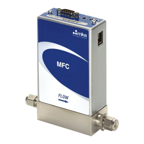
The MKS Type 1152C Mass Flow Controller (MFC) is designed for precise and repeatable mass
flow control of most low vapor pressure liquid or solid source materials into low pressure
processes such as Low Pressure Chemical Vapor Deposition (LPCVD), Metal Organic Molecular
Beam Epitaxy (MOMBE), and others. Mass flow measurement and control is accomplished
without the need of bubbler systems or thermal mass flow sensors. The 1152 MFC uses a pair of
absolute pressure sensors and an integral PID controller to control the mass flow rate. For
viscous laminar flow, the product of the average absolute pressure (PAVE), and the differential
pressure (∆P), is linearly proportional to the mass flow rate. The 1152 unit calculates this
product and appropriately scales the result to a 0 to 5 VDC output signal that is equal to 0 to
100% full rated flow for the calibrated gas and temperature.
Caution The control valve in the 1152 Mass Flow Controller is not a positive
shutoff valve. Depending upon your application, you may need to
install a separate positive shutoff valve.
The instrument is temperature controlled, and it is supplied with a computer generated
Calibration Curve and Calibration Data Sheet for the application specified when the unit was
ordered.
Note The 1152 MFC is optimized at the factory for the application parameters
specified when the unit was ordered. Contact the MKS Applications
group for a new calibration curve if your application parameters change.
The standard 1152 MFC is available with the factory set operating temperature range from 30°to
100°C. The high temperature option provides an operating temperature range of 90°to 150°C.
The 1152 MFC is bag packaged in a clean room environment.
Artisan Technology Group - Quality Instrumentation ... Guaranteed | (888) 88-SOURCE | www.artisantg.com

How This Manual is Organized Cha
p
ter One: General Information
4
How This Manual is Organized
This manual is designed to provide instructions on how to set up, install, and operate a Type
1152 unit.
Before installing your Type 1152 unit in a system and/or operating it, carefully read and
familiarize yourself with all precautionary notes in the Safety Messages and Procedures
section at the front of this manual. In addition, observe and obey all WARNING and
CAUTION notes provided throughout the manual.
Chapter One, General Information, (this chapter) introduces the product and describes the
organization of the manual.
Chapter Two, Installation, explains the environmental requirements and describes how to mount
the instrument in your system.
Chapter Three, Overview, gives a brief description of the instrument and its functionality.
Chapter Four, Operation, describes how to use the instrument and explains all the functions and
features.
Chapter Five, Maintenance, lists any maintenance required to keep the instrument in good
working condition.
Chapter Six, Troubleshooting, provides a checklist for reference should the instrument
malfunction.
Appendix A, Product Specifications, lists the specifications of the instrument.
Appendix B, Calibration Data Sheet, shows an example of the Calibration Data Sheet that is
shipped with each unit.
Customer Support
Standard maintenance and repair services are available at all of our regional MKS Calibration
and Service Centers, listed on the back cover. In addition, MKS accepts the instruments of other
manufacturers for recalibration using the Primary and Transfer Standard calibration equipment
located at all of our regional service centers. Should any difficulties arise in the use of your Type
1152 instrument, or to obtain information about companion products MKS offers, contact any
authorized MKS Calibration and Service Center. If it is necessary to return the instrument to
MKS, please obtain an ERA Number (Equipment Return Authorization Number) from the MKS
Calibration and Service Center before shipping. The ERA Number expedites handling and
ensures proper servicing of your instrument.
Please refer to the inside of the back cover of this manual for a list of MKS Calibration and
Service Centers.
Warning All returns to MKS Instruments must be free of harmful,
corrosive, radioactive, or toxic materials.
Artisan Technology Group - Quality Instrumentation ... Guaranteed | (888) 88-SOURCE | www.artisantg.com

Chapter Two: Installation How To Un
p
ack the T
yp
e 1152 Unit
5
Chapter Two: Installation
How To Unpack the Type 1152 Unit
MKS has carefully packed the Type 1152 unit so that it will reach you in perfect operating order.
Upon receiving the unit, however, you should check for defects, cracks, broken connectors, etc.,
to be certain that damage has not occurred during shipment.
Note Do not discard any packing materials until you have completed your
inspection and are sure the unit arrived safely.
If you find any damage, notify your carrier and MKS immediately. If it is necessary to return the
unit to MKS, obtain an ERA Number (Equipment Return Authorization Number) from the MKS
Service Center before shipping. Please refer to the inside of the back cover of this manual for a
list of MKS Calibration and Service Centers.
Note The 1152 MFC is supplied with Cajon®8-VCR®male fittings. Be sure
to keep the MFC bagged with the sealing surfaces protected to ensure
safe, leak-free installation and operation.
Caution Only qualified individuals should perform the installation and any
user adjustments. They must comply with all the necessary ESD and
handling precautions while installing and adjusting the instrument.
Proper handling is essential when working with all highly sensitive
precision electronic instruments.
Unpacking Checklist
Standard Equipment:
•Type 1152 Unit
•Type 1152 Instruction Manual (this book)
Optional Equipment:
•Electrical Connector Accessories Kit - 1152C-K1
•Interface cables
Artisan Technology Group - Quality Instrumentation ... Guaranteed | (888) 88-SOURCE | www.artisantg.com

Interface Cables Cha
p
ter Two: Installation
6
Interface Cables
As of January 1, 1996, all products shipped to the European Community must comply with the
EMC Directive 89/336/EEC, which covers radio frequency emissions and immunity tests. MKS
products that meet these requirements are identified by application of the CE Mark.
This MKS product meets CE requirements, per EMC Directive 89/336/EEC. To ensure
compliance when installed, an overall metal braided shielded cable, properly grounded at both
ends, is required during use.
Standard Cables
Standard cabling is available to interface the 1152 unit with both the display set point electronics
and the power supply. Refer to Table 1 for a list of cables to attach to other MKS equipment.
Note 1. An overall metal braided shielded cable, properly grounded at both
ends, is required during use to meet CE specifications.
2. To order an overall metal braided shielded cable, add an “S”after the
cable type designation. For example, to order a standard connection
cable to connect the 1152 MFC to a 260PS-1 power supply, use part
number CB260-3-10; for an overall metal, braided, shielded cable use
part number CB260S-3-10.
Interface Cables
To Connect To . . . Standard Cable Metal Braided, Shielded Cable
246, 247 CB259-5-10 CB259S-5-10
647 CB147-1-10 CB147S-1-10
260PS-1/260PS-3 CB260-3-10 CB260S-3-10
Table 1: Interface Cables
For a Flow System Using All MKS Equipment
When you purchase a complete mass flow control system, specifying all companion MKS
equipment at the time of purchase, MKS will provide the appropriate cable(s) in standard lengths
for a nominal cost.
For a Flow System Using Non MKS Equipment
A shielded cable assembly, (part number CB259S-6) in a nominal 10 foot (3 m) length, with a
Type “D”connector on one end and terminated in “flying leads”(pigtail) fashion on the other
end are available from MKS.
Note Units with flying leads are not CE compliant.
Artisan Technology Group - Quality Instrumentation ... Guaranteed | (888) 88-SOURCE | www.artisantg.com

Chapter Two: Installation Interface Cables
7
Generic Shielded Cable Description
MKS offers a full line of cables for all MKS equipment. Should you choose to manufacture your
own cables, follow the guidelines listed below to ensure CE compliance:
1. The cable must have an overall braided shield, covering all wires. Neither aluminum foil
nor spiral shielding will be as effective; using either may nullify regulatory compliance.
2. The connectors must have a metal case which has direct contact to the cable’s shield on
the whole circumference of the cable. The inductance of a flying lead or wire from the
shield to the connector will seriously degrade the shield’s effectiveness. The shield
should be grounded to the connector before its internal wires exit.
3. With very few exceptions, the connector(s) must make good contact to the device’s case
(ground). “Good contact”is about 0.01 ohms; and the ground should surround all wires.
Contact to ground at just one point may not suffice.
4. For shielded cables with flying leads at one or both ends; it is important at each such end,
to ground the shield before the wires exit. Make this ground with absolute minimum
length. Refer to Figures 1 and 2, page 8. (A ¼inch piece of #22 wire may be
undesirably long since it has approximately 5 nH of inductance, equivalent to 31 ohms at
1000 MHz). After picking up the braid’s ground, keep wires and braid flat against the
case. With very few exceptions, grounded metal covers are not required over terminal
strips. If one is required, it will be stated in the Declaration of Conformity or in the
instruction manual.
5. In selecting the appropriate type and wire size for cables, consider:
A. The voltage ratings;
B. The cumulative I2R heating of all the conductors (keep them safely cool);
C. The IR drop of the conductors, so that adequate power or signal voltage gets to the
device;
D. The capacitance and inductance of cables which are handling fast signals, (such as
data lines or stepper motor drive cables); and
E. That some cables may need internal shielding from specific wires to others; please
see the instruction manual for details regarding this matter.
Artisan Technology Group - Quality Instrumentation ... Guaranteed | (888) 88-SOURCE | www.artisantg.com

Interface Cables Cha
p
ter Two: Installation
8
Example 1: Preferred Method To Connect Cable
(shown on a transducer)
Transducer
Overall Insulation
(if present)
Bare Metal Cable Clamp
Makin
g
Firm Contact To Braid
Braid Here Is Desirable
(but not usually necessary)
Keep Wires and Braid
Flat A
g
ainst Case
Metal Cable Clamp
Screw
Split Lock Washer
External Tooth Lock Washer
Transducer Housin
g
Optional Plastic or Metal Cable
Clamp (For Physical Strain Relief)
Figure 1: Preferred Method to Connect an Overall Metal Braided Shielded Cable
Example 2: Alternate Method To Connect Cable
(shown on a transducer)
Transducer
Overall Insulation
(
if present
)
Braid Strands Twisted
Under Washer
Keep Wires Flat
A
g
ainst Case
Optional Plastic or Metal Cable
Clamp
(
For Ph
y
sical Strain Relief
)
Screw
Split Lock Washer
Flat Washers
External Tooth Lock Washer
Transducer Housin
g
Figure 2: Alternate Method To Connect an Overall Metal Braided Shielded Cable
Use this method when cable clamp is not available
Artisan Technology Group - Quality Instrumentation ... Guaranteed | (888) 88-SOURCE | www.artisantg.com

Chapter Two: Installation Product Location and Re
q
uirements
9
Product Location and Requirements
Operating Environmental Requirements
•Ambient Operating Temperature: 0°C to 50°C (32°F to 122°F)
•Ventilation requirements include sufficient air circulation
Caution The control valve in the 1152 Mass Flow Controller is not a positive
shutoff valve. Depending upon your application, you may need to
install a separate positive shutoff valve.
Setup
The 1152 MFC is bag packaged in a clean room environment. Keep the unit bagged prior to
installation. The 1152 MFC is supplied with Cajon 8-VCR type male fittings. It is important to
protect the fitting seal surfaces since damaged seal surfaces may leak. Always follow the
manufacturer’s recommended installation instructions.
Dimensions
Note All dimensions are listed in inches with millimeters referenced in
parentheses.
2.62
(66.5) 3.12
(79.2)
0.25 (6.35) Wide Slots
9.50 (241)
0.35 (8.9)
0.25
(6.35)
8.75 (222)
10.25 (260)
ZERO GAIN
Figure 3: Top View of the 1152 Unit
Artisan Technology Group - Quality Instrumentation ... Guaranteed | (888) 88-SOURCE | www.artisantg.com

Setup Cha
p
ter Two: Installation
10
Outlet
Inlet
6
Temperature
Switch
Temperature Deviation LED
1.50
(38.1)
7.28
(185)
:$51,1*
Vapors may combust when
operating above their flashpoint.
This instrument was
factory set at oC.
Prior to operating unit:
A) Read and fully understand manual
B) Verify installed leak tight integrity
Warnin
g
Label 1
2
3
4
5
6
7
8
9
10
11
12
13
14
15
1
2
3
4
5
6
7
8
9
SIGNAL CONDITIONER HEATER SUPPLY
VALVE TEST PT.
FLOW SIG.OUT
VALVE CLOSE
VALVE OPEN
PWR COM.
-15 VDC
+15 VDC
SET PT. INPUT
TEMP OUTPUT
OPTIONAL INPUT
SIG. COM.
SIG. COM.
P1-TEST SIG.
P2-TEST SIG.
CHASSIS
+15 VDC
NO CONNECTION
-15 VDC
TEMP. RELAY (N.O.)
TEMP. RELAY (COM.)
CHASSIS
CHASSIS
TEMP. RELAY (N.C.)
PWR COM.
CONNECTOR PINOUTS
Test Points
Figure 4: Back View of the 1152 Unit
J15 Connector
J9
Connector
6.00
(152.4)
6.69
(169.9)
Figure 5: Side View of the 1152 Unit
Artisan Technology Group - Quality Instrumentation ... Guaranteed | (888) 88-SOURCE | www.artisantg.com
Chapter Two: Installation Setu
p
11
Mounting
The 1152 unit has four mounting holes in its base plate as shown in Figure 6. The centers of
these slots form a rectangle 8.75 inches long by 2.62 inches wide.
Mounting Holes Mounting Holes
Figure 6: Location of the Mounting Holes
Follow these guidelines when mounting the 1152 unit:
Warning Read and follow all messages in
Safety Procedures and
Precautions,
page1, BEFORE attempting to install the 1152
unit. Failure to adhere to these messages could result in
injury to personnel.
1. Close all valves between the 1152 MFC and the vapor source before installing the unit.
2. Connect the input fitting on the 1152 unit to the vapor source.
3. Connect the outlet fitting to the downstream side.
4. Allow clearance to provide access to the connectors and the ZERO and GAIN pots.
Artisan Technology Group - Quality Instrumentation ... Guaranteed | (888) 88-SOURCE | www.artisantg.com

Table of contents
Other MKS Controllers manuals
Popular Controllers manuals by other brands

Icop
Icop VDX-6317-X user manual

Woodward
Woodward ProTech-GII Installation and operation manual

LSIS
LSIS XGT Series user manual

Ariston
Ariston AST 100 Installation, commissioning and user instructions

Hoval
Hoval TopTronic C-SYS operating manual

Heatcraft
Heatcraft H-IM-QRC Installation and operation manual

Emerson
Emerson Control Link Installation and operation manual

Eaton
Eaton xComfort CSEZ-01/19 Assembly instructions

Mitsubishi Electric
Mitsubishi Electric PAR-U01MEDU Smart ME Instruction book

Epever
Epever Tracer-AN Series user manual

YASKAWA
YASKAWA MP210 Series user manual

Delta Electronics
Delta Electronics AH500 Operation manual