3
Check the contents of box I, II and III.
Note: The contents of your package have been carefully selected and packed.
If, however, you noce that parts are missing, please get in touch with Babboe.
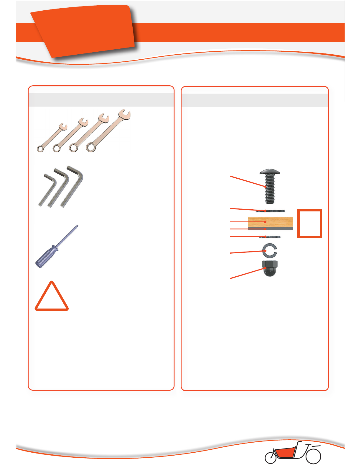
Check Contents of box I, II and III
Box I contents (hwwx-702) Box II contents (hwwx-701)
o Front frame, including front wheel
(20 inch)
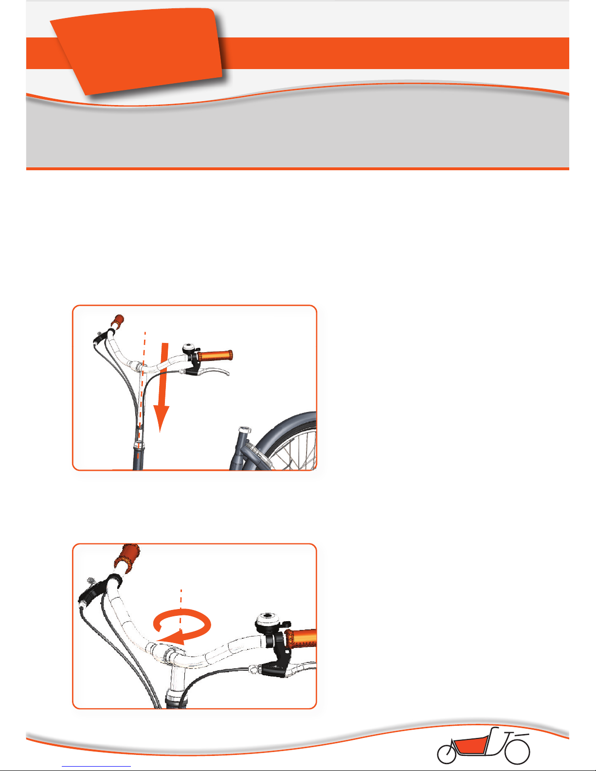
o Steering rod
o Complete kickstand (in a box)
o Long box containing:
o Front frame beam
o Frame aachment prole
o Aachment proles for the
cargo box
o Rear frame, including rear wheel
(26 inch)
o Box containing the saddle
o Box containing:
o Tool set
o Sachets labeled A through J
(bolts, nuts and washers)
o Saddle post
o Pedals
o 2 cords
o Instrucons for the Shimano
gear system
Box III contents (hwwx-703)
o Cargo box panels:
o Front panel
o Rear panel
o Boom panel
o Side panel (le)
o Side panel (right)
o Cargo box seat (for placement
near the handlebars)
TIPS for assembly:
- Be careful when opening the boxes with
a knife, as the parts inside may become
damaged.
- Cut open and unfold the boxes so you
can lay them down as a surface for the
assembly.
- Have a garbage bag at hand to discard
packaging material and other rubbish.
- When the instrucons prompt you to use
a sachet, use a plasc container to empty
the sachet of nuts and bolts into. This
will allow you to work eciently and not
misplace or lose any parts.