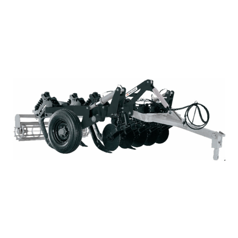
Baldan CRI-E User manual

Drag Type Oset Disc Harrow Remote Control - Special
CRI-E


We thank you for the preference and congratulate your excellent choice in acquiring an
implement of outstanding quality, manufactured in accordance with the advanced
technology of BALDAN IMPLEMENTOS AGRÍCOLAS S/A.
This manual will assist you, in proceeds necessaries, since when you bought until the op-
erational proceeds application, security and maintenance.
The BALDAN guarantees that deliver this implement to the dealer, working properly, and in perfect
conditions.
The dealers it’s under the responsibility to keep the protection and conservation while keep the implement in your stock, and
than, to assembly, tighten, lubrication and overhaul.
On time of the technical deliver, the dealer must to have conducted the user customer about the manutentation, safety, and
your obligations in a possible technical assistance, the obligation to see the warranty terms and read the instruction manual.
Any solicitation of warranty, please contact our Baldan technical service, by your Baldan dealer that you bought our implement.
Rearm the necessity to read carefully of warranty certicate and note all of items from this manual, therefore you will increase
the working life of your equipment.
INTRODUCTION

Drag Type Oset Disc Harrow Remote Control - Special
CRI-E

INDEX
WARRANTY .......................................................................................................................................................................................................................... 5
Product Warranty............................................................................................................................................................................................................................................................................ 5 - 6
GENERAL INFORMATION................................................................................................................................................................................................... 7
To the ower...................................................................................................................................................................................................................................................................................... 7
SAFETY RULES ..................................................................................................................................................................................................................... 8 - 10
WARNINGS ........................................................................................................................................................................................................................... 11 - 12
COMPONENTS..................................................................................................................................................................................................................... 13
TECHNICAL SPECIFICATIONS............................................................................................................................................................................................ 14
MOUNTING .......................................................................................................................................................................................................................... 14
Mounting of Disc Section (Figure 02) ............................................................................................................................................................................................................................................... 14 - 15
Mounting of Finish Disc (Figure 03) ................................................................................................................................................................................................................................................. 15
Mounting of Disc Sections - CRI-E 36 / 40 Discs (Figures 04)............................................................................................................................................................................................................. 16
Mounting of Disc Sections - CRI-E 44 / 48 Discs (Figures 05)............................................................................................................................................................................................................. 17
Mounting of Frames (Figure 06) - Cri-E 36 / 40 / 44 Discs................................................................................................................................................................................................................. 18
Mounting of Frames (Figures 07) - Cri-E 48 Discs ............................................................................................................................................................................................................................. 18
Mounting of Disc Section on the Frame (Figures 08)......................................................................................................................................................................................................................... 19
Mounting of Bars and Cleaners (Figures 09)..................................................................................................................................................................................................................................... 20
Mounting of Wheel Shafts (Figure 10)............................................................................................................................................................................................................................................. 20 - 21
Mounting of Coupling Header (Figure 11)........................................................................................................................................................................................................................................ 22
Mounting the Hydraulic System (Figure 12) ..................................................................................................................................................................................................................................... 23
Mounting of The Back Coupler (Figure 13) ....................................................................................................................................................................................................................................... 24
Mounting of Warning Sign (Figure 14)............................................................................................................................................................................................................................................. 24
OPERATIONS........................................................................................................................................................................................................................ 25
Coupling the Harrow to Traction Bar of the Tractor (Figure 15)......................................................................................................................................................................................................... 25
Adjustment of Harrow Spacing (Figures 16)..................................................................................................................................................................................................................................... 25 - 26
TRANSPORTATION / WORK ............................................................................................................................................................................................... 27
Transportation (Figures 17) ............................................................................................................................................................................................................................................................ 27

Work (Figures 18) ........................................................................................................................................................................................................................................................................... 27
Harrow Displacement (Figure 19) .................................................................................................................................................................................................................................................... 27
Crossbar Adjustment (Figure 20)...................................................................................................................................................................................................................................................... 28
Adjustment of Stabilizer Bar and Complete Adjuster ........................................................................................................................................................................................................................ 28
How to Start Harrowing .................................................................................................................................................................................................................................................................. 29
Harrowing from Outside to Inside (Figure 22) .................................................................................................................................................................................................................................. 29
Harrowing from Inside to Outside (Figure 23) .................................................................................................................................................................................................................................. 29
Plots With Level Curves (Figure 24).................................................................................................................................................................................................................................................. 29
OPERATIONS........................................................................................................................................................................................................................ 30
MAINTENANCE.................................................................................................................................................................................................................... 31
Tire Pressure (Figure 25) .................................................................................................................................................................................................................................................................. 31
Lubrication ..................................................................................................................................................................................................................................................................................... 32
Table of Greases and Equivalents (Table 9)....................................................................................................................................................................................................................................... 32
Lubricate every 60 working Hours (Figures 26) ................................................................................................................................................................................................................................ 33
Self-lubricating Bushings (Figure 27)............................................................................................................................................................................................................................................... 33
Discs ............................................................................................................................................................................................................................................................................................... 34
Bearings ......................................................................................................................................................................................................................................................................................... 34
Adjustment of Bearings (Figure 28) ................................................................................................................................................................................................................................................. 34
CALCULATIONS ................................................................................................................................................................................................................... 35
Approximate Production.................................................................................................................................................................................................................................................................. 35
Approximate Hourly Production Table.............................................................................................................................................................................................................................................. 35
CLEANING ............................................................................................................................................................................................................................ 36
Cleaning and Storage (Figure 29)..................................................................................................................................................................................................................................................... 36
IDENTIFICATION.................................................................................................................................................................................................................. 37
Product Identication (Figure 30).................................................................................................................................................................................................................................................... 38
Notes .............................................................................................................................................................................................................................................................................................. 39
WARRANTY .......................................................................................................................................................................................................................... 37
Certicate of Warranty .................................................................................................................................................................................................................................................................... 40 - 47

Instruction Manual
5 CRI-E
ABALDAN IMPLEMENTOS AGRÍCOLAS S/A, ensures the dealer normal performance of the implement for a period of six () months
as of the delivery date on the retail invoice to the rst nal consumer.
During this period, BALDAN undertakes to repair defects in material and/or of manufacture of its liability, including labor, freight
and other expenses of the dealer’s liability.
In the warranty period, request and replacement of eventual defective parts shall be made to the dealer of the area, who will
submit the faulty piece for BALDAN analysis.
When this procedure is not possible and the resolving capacity of the dealer is exhausted, the dealer will request the support of
BALDAN Technical Assistance through a specic form distributed to dealers.
After analyzing the replaced items by BALDAN Technical Assistance, and concluding that it is not a warranty, then the
dealer will be responsible for the costs related to the replacement; as well as material expenses, travel including accommodation
and meals, accessories, lubricant used and other expenses arising from the call out toTechnical Assistance, and BALDAN company
is authorized to carry the respective invoice in the name of the resale.
PRODUCT WARRANTY
WARRANTY

Instruction Manual
CRI-E 6
Any repair carried out in the product within the dealer warranty deadline will only be authorized by BALDAN upon previous
budget presentation describing parts and workforce to be executed.
The product is excluded from this term if it is repaired or modied by representatives not belonging to the BALDAN dealer
network, as well as the application of non-genuine parts or components to the user’s product.
This warranty is void where it is found that the defect or damage is caused by improper use of the product, failure to follow
instructions or inexperience of the operator.
It is agreed that this warranty does not cover tires, polyethylene tanks, cardan shafts, hydraulic components, etc., which are
equipment guaranteed by their manufacturers.
Manufacturing and/or material defects, object of this warranty term, will not constitute, under any circumstances, grounds for
termination of a purchase agreement, or for indemnication of any nature.
BALDAN reserves the right to change and/or perfect the technical characteristics of its products, without previous notice, and
without obligation to proceed in the same way with the products previously manufactured.

Instruction Manual
7 CRI-E
The incorrect handling of this equipment may result in severe or fatal accidents. Before starting the equipment, carefully read the instructions contained in this
manual. Make sure that the person responsible for the operation is instructed as the correct and safe handling. Also make sure that the operator has read and
understood the instructions manual of the product.
NR-31 - SAFETY AND HEALTH AT WORK IN AGRICULTURE, LIVESTOCK FORESTRY, FOREST EXPLORATION AND AQUACULTURE.
The purpose of this Regulatory Standard is to establish the precepts to be observed in the organization and in the work environment, in a
manner compatible with the planning and development of agriculture, livestock, forestry and aquaculture activities with the safety and
health and environment work environment.
TO THE OWNER
BALDAN IMPLEMENTOS AGRÍCOLAS S/A,is not responsible for any damaged caused by accident due to usage, transportation, or in the improper or incorrect
transportation of its implement, whether by negligence and/or inexperience of any person.
Only people with complete knowledge of the tractor and the implement should carry their transportation and operation.
BALDAN is not responsible for any damaged caused in unpredictable or unrelated situations to the normal use of the implement.
For more information, refer to the site and read in full NR-31.
http://portal.mte.gov.br/legislacao/normas-regulamentadoras-1.htm
GENERAL INFORMATION
MR. OWNER OR OPERATOR OF THE EQUIPMENT.
Read and carefully comply with provisions of NR-31.

Instruction Manual
CRI-E 8
WARNING WARNING WARNING WARNING
• Read this instruction manual ca-
refully to know the recommen-
ded safety rules.
• Only start the tractor opera-
tions, when are you properly ac-
commodated and with the seat
belt fasted.
• Never carry people over the tractor
or equipment.
• There are risks of serious injury by
tipping when working on slopes.
• Never use excessive speed.
SAFETY RULES
THIS ALERT SYMBOL INDICATES IMPORTANT SAFETY NOTES. WHENEVER YOU FIND IT IN THIS MANUAL, READ THE MESSAGE WITH
ATTENTION TO AVOID ANY ACCIDENT.

Instruction Manual
9 CRI-E
WARNING WARNING WARNING
• Do not work with the tractor
if the front bee without enough
weight to the rear equipment.
There is tendency to lift , add wei-
ghts at front or front wheels.
• Before any equipment main-
tenance, make sure that is pro-
perly stopped
• Avoid getting hit.
• Keep always away from the
machine’s active elements (discs),
they are sharp and can cause acci-
dents.
• Whencarryingout any service onthe
discs, use safety gloves on his hands.
WARNING
• Dispose residues inappropriately
aects the environment and the eco-
logy since you will be polluting, canais
or the soil.
• Inform yourself about the proper way
or recycling or disposing residues.
PROTECT THE ENVIROMMENT!
SAFETY RULES

Instruction Manual
CRI-E 10
WARNING
WARNING
• Do not make adjustments to
the CRI-E during operation.
• When doing any service on the
CRI-E, turn o the tractor rst.
Use appropriate tools.
• Neverweld thewheelmounted with tire,
the heat may cause air pressure increase
and provoke the explosion of the tire.
• When lling the tire, stand at the side of
the tire, never in froint of it.
• When lling the tire, always use a
containment device (lling cage).
WARNING WARNING
•
The hydraulic system operate with a high
pressure uid, existing risk of serious injuries or
death, search for damaged hose every day and
replace it.
•
Before coupling or uncouple the hoses relief
the pressure, using the tractor’s control when it
is turned o.
• Remove the ignition key before
performing any maintenance on
the CRI-E. Protect yourself from
possible injury or death caused
by suddenly starting the CRI-E.
• If the CRI-E is not properly enga-
ged, do not start the tractor.
SAFETY RULES
FOLLOW ALL RECOMENDATIONS, WARNINGS AND SAFE PRACTICES RECOMMENDED IN THIS MANUAL, UNDERSTAND THE IMPORTANCE
OF YOUR SAFETY. ACCIDENTS MAY LEAD TO DISABILITY OR INCLUDING DEATH. REMEMBER, ACCIDENTS CAN BE AVOIDED!

Instruction Manual
11 CRI-E
01 - When operate with the implement, do not allow people to stay close or above the implement. (The platforms are used to supply the stores
and not to transport people).
02 - During assembly or desassembly the discs section use proctection gloves.
03 - When turn on or o the hydraulic rubbers, alleviate the circuit pressure.
04 - Check periodically the rubbers conservation. If there is indicium of oil emptying change it immediatelly because the oil works under high
pressure and may cause serious damages.
05 - Do not use much large clothes because they can fasten the implement.
06 - Putting in action the tractor, be correctly placed at the operator seat and aware about the correct and safety handling both tractor and
implement. Place always the gearshift crank at the neutral position, turn o the gear of the power command and place the hydraulic commands at
the neutral position.
07 - Do not turn on the tractor in a closed place, without appropriate ventilation because the gas are bad for health.
08 - While maneuver the tractor to clamp the implement be sure if there is space enough and nobody is too much close, maneuver always in slow
gear and be ready to brake in case of emergency.
09 - Do not adjust the implement working.
WARNINGS

Instruction Manual
CRI-E 12
10 - Working in inclined soil try to keep the necessary stability. In case of instability reduce the acceleration, turn the wheels to the inclined side
of the soil and never lift the implement.
11 - Conduct the tractor always in safety speeds, specially working in irregular or inclined soil, keep the tractor always geared.
12 - In case of conducting the tractor on road, keep the brake pedal connected.
13 - Do not work with the front of the tractor light. If there is trend to lift up add more weight in front or at the front wheels.
14 - Getting out the tractor place the gearshift at the neutral position and apply the park brake. Do never let clamped implements at the tractor
with the hydraulic system at the lifted position.
15 - Drugs and alcohol will aect an operator’s alertness and coordination. Do not operate any engine under these conditions.
16 - Explain the operation, inspect and maintenance instructions to those users or operators who can not read.
WARNINGS

Instruction Manual
13 CRI-E
Figure 01
COMPONENTS
01 - Front Frame
02 - Back Frame
03 - Stiener
04 - Stabilizer Rod
05 - Piston
06 - Piston Lock
07 - Hoses
08 - Complete Adjuster
09 - Back Coupler for Harrow Roller
10 - Coupling Header
11 - Mechanical Jack
12 - Coupling Shackle
13 - Disc
14 - Front Cleaner
15 - Keys
16 - Piston Limiter
17 - Articulation Shaft Hub
8
15
7
4
5
2
6
1
10
9
3
20
21 22
11
23
12
7
18
16
19
CRIE DRAGTYPE OFFSET DISC HARROW REMOTE CONTROL SPECIAL
18 - Wheel Articulation Shaft
19 - Tire
20 - Finish Disc
21 - Reel
22 - Bearing
23 - Rear Cleaner
13
14
17

Instruction Manual
CRI-E 14
Table 1
Baldan reserves the right to change the technical features of this product without prior warning.
The technical specications are approximate and informed in the normal working conditions.
Model Number
of Discs
Disc
Diameter (ø)
Disc Thickness
(mm)
Shaft
Diameter (ø)
Working
Width (mm)
Working
Depth (mm)
Spacing between
Discs (mm)
Approximate
Weight with
28” x 6mm Disc (kg)
Approximate
tractor power (HP)
CRI-E 36 28” 6,0 e 7,5 1.5/8” 4826 150 a 250 262 4652 210 a 230
CRI-E 40 28” 6,0 e 7,5 1.5/8” 5360 150 a 250 262 4883 240 a 260
CRI-E 44 28” 6,0 e 7,5 1.5/8” 5896 150 a 250 262 5115 264 a 280
CRI-E 44 28” 6,0 e 7,5 1.5/8” 6432 150 a 250 262 5345 288 a 303
- When mounting the CRI-E, always start with the set of discs and proceed as follows:
1 - Place the concave thrust washer (2) on the shaft (1), followed by the nut (3), latch (4), securing it with the pressure washer (5) and screw (6).
2 - Then put the disc (7), bearing (8), another disc (7), separator reel (9) on the shaft (1) and so on successively, as shown in gure 2.
3 - When the set is complete with all the discs, bearings, separator reels, put the convex thrust washer (10) and the other nut (3), tightening with the
key until the entire set is rmly secured.
TECHNICAL SPECIFICATIONS
MOUNTING
MOUNTING OF DISC SECTION FIGURE 02

Instruction Manual
15 CRI-E
7
3
2
1
4
7
611
54
Figure 02
4- Then wedge the set of discs and tighten the nut (3) through im-
pacts. When the maximum tightness is almost achieved, adjust the
lock (4) on the convex washer (10) tightening the nut until the hole
coincides and secure it with the pressure washer (5) and screw (6).
5
6
7
9
7
8
3
10
7
9
9
8
7
- To mount the nish disc, proceed as follows:
1 – Place the concave thrust washer (2) on the shaft (1), followed by the nut (3), latch (4), securing it
with the pressure washer (5) and screw (6).
2 – Then put the nish disc (7), reel (8), disc (9) and bearing (10) on the shaft (1) and so on successively, as
shown in gure 3. Figure 03
MOUNTING OF FINISH DISC FIGURE 03
Use safety gloves on your hands when performing
mounting and dismouting services on the discs.
Do not use loose clothing because it can get caught
on the equipment.
ATTENTION

Instruction Manual
CRI-E 16
C
D
abC
C
C
C
D
ab
C
C
C
CRIE 36 DISCS CRIE 40 DISCS Figures 04
MOUNTING OF DISC SECTIONS FIGURES 04 CRIE 36 / 40 DISCS

Instruction Manual
17 CRI-E
C
D
abC
C
C
C
D
ab
C
C
C
CRIE 44 DISCS CRIE 48 DISCS Figures 05
MOUNTING OF DISC SECTIONS FIGURES 05 CRIE 44 / 48 DISCS

Instruction Manual
CRI-E 18
Figure 06
- To mount the front and back frames of the CRI-E, proceed as follows:
1 - Put the front frames (1) and back frames (2) on a at and clean
place.
2 - Then put the stiener (3) on the front (1) and back frames (2),
securing them with the screw (4), latch (5), at washer (6), pressure
washer (7) and nut (8).
8
67
5
4
2
3
1
- To facilitate loading and transportation, CRI-E 48 discs leaves the
factory with the front and back frames in parts, and these must be
mounted as follows:
1 - Couple the front frames (1 and 2) and secure them with the
screws (3), pressure washers (4) and nut (5). Repeat the procedure
for the back frames.
2 – Then put the stiener (3) on the front (1) and back frames (2),
securing them with the screw (4), latch (5), at washer (6), pressure
washer (7) and nut (8).
8
67
5
431
Figures 07
4
5
12
3
MOUNTING OF FRAMES FIGURES 07 CRIE 48 DISCS
MOUNTING OF FRAMES FIGURE 06 CRIE 36 / 40 / 44 DISCS
Table of contents
Other Baldan Farm Equipment manuals

Baldan
Baldan SPDE CXP User manual

Baldan
Baldan CRI User manual

Baldan
Baldan CRSG 32 User manual

Baldan
Baldan CRSG 12 User manual

Baldan
Baldan GTCR 34 User manual

Baldan
Baldan CRSG 32 User manual

Baldan
Baldan MOVERE User manual

Baldan
Baldan PNA 3000 User manual

Baldan
Baldan GTCR User manual

Baldan
Baldan ASDA User manual
Popular Farm Equipment manuals by other brands

Chore-Time
Chore-Time TURBO-COOL 46963 instruction manual

Curtis
Curtis Kubota M62 TLB Installation & owner's manual

Quicke
Quicke Q 640 instruction manual

Brinsea
Brinsea ChickSafe Eco Door Opener Installation and operating instructions

Amazone
Amazone Cayros Series operating manual

RITEWAY
RITEWAY F Series Operator's manual & parts list