BEA SUPERSCAN-T User manual

75.5911.02 20180226 Page 1 of 9
COMPONENT ID
PRESENCE SENSOR w/MONITORING
The SuperScan-T detector is a door-mounted presence detection system that is used on automatic pedestrian swing doors. The
SuperScan-T can be used on a monitored or non-monitored system. Unlike other door-mounted sensing devices, the SuperScan-
T's unique electronic architecture allows the detection modules to be mounted near the top of the door, out of harm's way. A rotating
cam is used for the range adjustment of the detection zone. Width patterns may be altered by adding Slave modules to the Master
module. These Slave modules are simply added by inserting them into the aluminum extrusion, then connecting them with the
attached flat ribbon cable to the next module without interrupting other modules in the same extrusion. Once installed, the detection
zone (in addition to being adjustable for distance) can be angled independently from the other modules.
Each SuperScan-T module consists of two optics, a transmitter (TX) and a receiver (RX), and functions independently of the other
modules. The transmitter emits an extremely precise beam, which measures approximately 4" in diameter at a distance of 8'. The
receiver, in turn, receives the infrared beam reflected off of the floor. This transmission and reception forms a detection triangle,
which is the basic premise of detection (called triangulation). Should this angle be interrupted, detection will occur. Detection is
NOT based upon the intensity of the beam, and in principle will not be affected by the color or background of the object that interrupts
the angle.
DESCRIPTION
SPECIFICATION
Power Supply
12 – 24 VAC/VDC ±10%
Current Consumption
Master:
On = 60 mA max.
Off = 30 mA max.
Slave:
On = 40 mA max.
Off = 30 mA max.
Inhibit Input
12 – 24 VAC/VDC ±10% (inhibited when voltage is applied)
Monitoring Request Input
12 – 35 VDC required (polarity-sensitive)
Min. pulse width duration 50 ms
Output Interface; relay
Relay – max. contact rating is 1A @ 30v (resistive)
Detection Range
0 – 8’
Distance Adjustment
2 – 8’ (rotating cam with linear adjustment)
Max. Mounting Height
8’
Detection Time
< 50 ms
Detection Signal Duration
Infinite Presence Detection
Output Hold Time
Potentiometer range: 0.1 – 4.5 seconds
LED Indications
Master:
Red LED = Detection
Green LED = Active Output
Slave:
Red LED = Detection
Operating Temperature Range
-30 – 140 ºF
PCB Dimensions
Master: 10.91” x 1.5”
Slave: 8.75” x 1.5”
Connector to Door Controller
8-position screw terminal on Master PCB
Connection: Master to Slave
Flat-ribbon cable w/connectors and key lock
Max. Number of Slaves
8
Functions Selection
Detection Mode: NO or NC
Normal Mode or Background Analysis Mode
• Shut off all power going to the header before attempting any wiring procedures.
• Maintain a clean and safe environment when working in public areas.
• Constantly be aware of pedestrian traffic around the door area.
• When performing testing, always stop pedestrian traffic through the doorway that may result in unexpected reactions by the
door.
• Before powering up, always check placement of all wiring and components to ensure that moving door parts will not catch any
wires and cause damage to equipment.
• Ensure compliance with all applicable safety standards (i.e. ANSI A156.10, 156.27) upon completion of installation.
SAFETY
PRECAUTIONS
!
CAUTION
DESCRIPTION
TECHNICAL
SPECIFICATIONS
SUPERSCAN-T
USER’S GUIDE
COMPONENT ID

75.5911.02 20180226 Page 2 of 9
q The sensor must be firmly
fastened to prevent vibration.
q Sensor must be in a location that does
not interfere with door hardware (finger
guards, lock rods, etc.).
q The sensor must not have any
unwanted objects likely to
move or vibrate in its path.
1. Remove the screw that secures the endcap to the SuperScan-T extrusion (image below, left).
2. Remove the plastic lens by pulling the lens out from the top of the extrusion (image above, right). Do not use a screwdriver to pry the lens, as
cracking may occur.
CAUTION!
REMOVE THE MASTER AND ALL SLAVE CIRCUIT BOARDS FROM THE ALUMINUM EXTRUSION
BEFORE PERFORMING ANY DRILLING.
WHEN COMPLETE, ENSURE THAT ALL METAL SHAVINGS ARE CLEANED FROM THE EXTRUSION
BEFORE RE-INSERTING THE CIRCUIT BOARDS.
3. The image below (left) shows the angle adjustment clip in its proper position within the extrusion (PCBs removed and clip shown at end of
extrusion for clarity only). To remove the clip, simply pull the tab out away and downward from the extrusion, then rotate the module out from
extrusion (image below, right). To re-install, simply reverse the procedure. The PCB must first be installed into the adjustment clip, then installed
into the aluminum extrusion.
IMPORTANT NOTE: The end of the extrusion that is towards the pivot end of a center-hung door, should be in far enough from the edge of
the door (image below, left) to prevent the endcap of the SuperScan-T from rubbing against the finger guard during door movement. Pay
particular attention on the safety side of the door. Hinge-hung doors will not require as much clearance between the end of the SuperScan-T
and hinge-side jamb (image below, right). At the leading edge of the door, the edge of the SuperScan-T, including the endcap, should be as
close as possible to the leading edge of the door, without creating mechanical interference with the door jamb or with an adjacent door (pairs).
4. Hold the SuperScan-T extrusion up to the top of the door. Ensure that the extrusion is oriented correctly.
1
MECHANICAL
INSTALLATION
PREPARING AND
MOUNTING THE
SENSOR
INSTALLATION
TIPS
Back Side
Top Side

75.5911.02 20180226 Page 3 of 9
5. Mark and drill the extrusion (in the approximate locations as shown below) where the mounting holes (one at each end) should
be located. Also, be sure to mark and drill the proper end for an additional hole to be used for wire passage. Wire passage
hole should be approximately ¼” diameter. Screw mount holes only serve as a pilot hole for ease of installing the self-drilling
screws that are provided.
NOTE: Take care to avoid screw holes near the seams of the door. It may be difficult to drill and install a screw, and may
possibly damage the inside structural braces of the door.
6. Hold the SuperScan-T back up to the door at the pre-drilled location and attach the unit to the door with the 2 screws provided. Ensure that the
SuperScan-T extrusion is tight against the door.
7. If SuperScan-Ts are to be mounted on both sides of the door, a wire passage hole will be required through the door to go from the approach
side to the safety side, as shown below. Again, be sure not to drill through any through-bolts or braces within the door. A The extension wire
going between the terminal blocks should be approximately 18” long and can then be cut back as needed.
8. Next, a wire passage hole will be required in the door header (image below, left) and also in the jamb tube (image below, right) at approximately
the same height as the SuperScan-T. The wire transfer hole in the jamb should be at the secure side of the door. Normally, this will be the
interior side. Feed the wire through the jamb tube up to the header. Ensure that enough wire is left out to reach the SuperScan-T terminal block.
NOTE: Ensure that there is enough slack in the cabling to allow for adequate movement of the cable throughout the range of door travel.
9. Once all cabling is in place, the plastic sheath must be installed over the wire coming out of the jamb tube. This must be done before making
final connection to the terminal block. The sheath may have to be cut to fit the application. Once the wire is fed though, the plastic cap may be
installed on the jamb, over the transfer hole.
Plastic ribbed sheath
MECHANICAL
INSTALLATION
PREPARING AND
MOUNTING THE
SENSOR

75.5911.02 20180226 Page 4 of 9
1. With cabling in place, wiring at the terminal connector (image below, left) on the SuperScan-T Master module may be
completed. Wiring will vary according to the application. Available positions on the connector are shown below:
2. Once all wiring has been completed, the endcaps and lens may be installed. At the SuperScan-T end of the cable (image below, A), leave
enough slack to allow a relaxed connection at the terminal block. Locate the SuperScan-T endcap that goes towards the hinge-end of the door.
Remove the tab at the bottom of the cap (image below, B) to allow insertion of the plastic sheath. Insert the plastic sheath (image below, C)
and install the endcap. The SuperScan-T lens may then be installed to fit tight against the endcap and plastic sheath to hold it in place (image
below, D). Leave the endcap off at the opposite end until all mechanical adjustments have been completed.
* Refer to the appendices of this document for various wiring schematics.
Terminal
Explanation of Wiring Connections
1
Test input (when used as a monitored sensor)
(+) positive when utilizing monitoring
2
Ground
(-) negative when utilizing monitoring
Negative terminal if Input inhibition is used
3
Input inhibition: All detection is ignored. Infrared emission is stopped.
Inhibition occurs when 12 – 24 VAC/VDC ±10% is applied between terminal 3 and terminal 2.
4
Normally Open: JP2 factory default will close the relay contact on terminal 4 when the SuperScan-T
is energized and not in detection. Loss of power results in a N.O. contact
5
Normally Closed: JP2 factory default will open the relay contact on terminal 5 when the SuperScan-
T is energized and not in detection. Loss of power will result in a N.C. contact.
6
Common contact for relay
7
Power Input (-): 12 – 24 VAC/VDC ±10% must be supplied
8
Power Input (+): 12 – 24 VAC/VDC ±10% must be supplied
21
ELECTRICAL
INSTALLATION-
CABLING &
CONNECTIONS
A
B
C
D

75.5911.02 20180226 Page 5 of 9
Master and Slave Module Jumper Settings: Prior to power-on, all jumper settings on the Master and Slave boards should be set
according to the installation.
Jumper settings include:
§ Function J1: Background Analysis (Master and Slave boards)
§ Function J2: Relay Mode (NO / NC) (Master board only)
§ Function J3: Monitoring Mode (Master board only)
§ Function J4: Master Only or Master and Slave Configuration (Master and Slave boards)
1. Jumper J1 (Background Analysis) is a 3-pin configuration located on each module. Background Analysis is the ability to analyze the background
in the area of the detection field, to help reduce chances of non-detection due to faulty environmental situations. When ON, Background Analysis
allows constant detection in the event of one or more of the following situations:
o Module aimed too high
o Module incorrectly oriented (towards sky, for example)
o Defective amplification chain
o Faulty infrared transmitter
o Not enough reflectivity off of floor surface
NOTE: Floor must have at least 5% reflectivity to allow Background Analysis to function properly.
This configuration greatly reduces the chance of allowing the modules to function less than optimally. If one of the above-stated faults exists,
the detector will remain active, thereby causing the door to stay open or to not open. This fail-safe operation will cause the door to be inoperative
in the automatic mode, since there will be a constant signal either to the safety input or to the activation input of the door control, depending on
which module is sensing detection. If an extremely IR-absorbent floor is present, set J1 to Background Analysis mode. The J1 function must
be set on each module.
Background Analysis Mode – 3-Pin Jumper: Center pin and left pin are for Normal Mode, center pin and right pin are for Background Analysis
mode.
2. J2 is a two-position jumper (ON THE MASTER BOARD ONLY), which enables either a passive or active relay to be selected. The
SuperScan-T comes factory-preset with the relay in the ACTIVE MODE.
ACTIVE RELAY: RELAY ENERGIZED WHEN DETECTOR IS AT REST
ACTIVE RELAY + NC & COM TERMINAL CONNECTION = CLOSED CONTACT DURING DETECTION
§ Use the NC and COM terminals (5 and 6) and leave JP2 at the factory-preset position.
§ LED indication during detection: Green LED is OFF, red LED is ON
§ Upon power loss, the contact will be closed.
ACTIVE RELAY + NO & COM TERMINAL CONNECTION = OPEN CONTACT DURING DETECTION
§ Use the NO and COM terminals (4 and 6) and leave JP2 at the factory-preset position.
§ LED indication during detection: Green LED is OFF, red LED is ON
§ Upon power loss, the contact will be open.
View Looking
Toward P1
J2
MECHANICAL
ADJUSTMENTS
PRIOR TO
POWER-ON
J2
View Looking
Toward P1

75.5911.02 20180226 Page 6 of 9
PASSIVE RELAY: RELAY DE-ENERGIZED WHEN DETECTOR IS AT REST
PASSIVE RELAY + NO & COM TERMINAL CONNECTION = CLOSED CONTACT DURING DETECTION
§ Use NO and COM terminals (4 and 6) and CHANGE JP2 from the factory-preset position.
§ LED indication during detection: Green LED is ON, red LED is ON
§ Upon power loss, the contact will be open.
PASSIVE RELAY + NC & COM TERMINAL CONNECTION = OPEN CONTACT DURING DETECTION
§ Use the NC and COM terminals (5 and 6) and CHANGE JP2 from the factory-preset position.
§ LED indication during detection: Green LED is ON, red LED is ON
§ Upon power loss, the contact will be closed.
3. Jumper J3 (located only on Master module) is to toggle the monitoring mode on and off.
§ Monitoring OFF = jumper installed on both pins (image below, left)
§ Monitoring ON = jumper removed (may be stored on one pin) (image below, right)
§ Monitoring is not available on Master modules without jumper J3 installed.
4. Jumper J4, is found on the Master and Slave modules. On the Master module, it determines ‘Master only’ or ‘Master and Slave’ configuration
for use when Monitoring is ON.
When the jumper is installed in ‘Master only’ configuration (image right, top), it is intended for use without
Slave modules added to the chain and is for ‘Master only’ operation. The jumper is located at the Output
end of the Master module. (‘Master only’ has jumper installed on two pins closest to center of board.)
With jumper J4 installed as shown in the image to the right (middle), the Master is intended for Slave
modules to be added. Jumper J4 is also installed on the last Slave module in the multi-module chain, near
the output end of the module.
As shipped From BEA, Inc., default placement of J4 jumpers is as follows:
§ If a Master ONLY is shipped: Jumper will be positioned for Master Only
§ If a Slave ONLY is shipped: No jumper on Slave J4 position
§ If a kit is shipped (i.e. SuperScan-T II): Jumpers correctly for monitoring in that configuration.
On the Slave module, jumper J4 should be installed on the last Slave module in the chain, as shown in the
image to the right (bottom). All Slave modules between the Master and the last Slave should have the
jumper removed.
There is a hold-time potentiometer (P1) located on the Master module. It is located between the receiver
and transmitter. Adjustability ranges from 0.1 – 4.5 seconds. When installed, clockwise rotation increases
time delay.
J2
View Looking
Toward P1
J4
MECHANICAL
ADJUSTMENTS
PRIOR TO
POWER-ON (cont.)
J2
View Looking
Toward P1
J4
View Looking Toward
Master Output
J4
View Looking Toward
Master Output

75.5911.02 20180226 Page 7 of 9
1. The positioning of the modules within the aluminum extrusion will be as shown below. The modules will always be positioned
so that the transmitter (TX) is at the leading-edge of the door. Modules may be flipped around to accommodate handing of
doors.
2. The angle of each module may be set independently. Use the charts below to help determine the angling. The angles may have to be altered
once the units have been powered up and walk-tested.
INACTIVE ZONE (B)
DISTANCE FROM FLOOR
SUPERSCAN-T ANGLE
0º
5º
10º
15º
20º
25º
8”
0
6"
12 ½"
19 ¼"
26"
33 ¼"
12”
0
6"
12"
18"
24 ½"
31 ½"
16”
0
5 ½"
11 ¼"
16 ¾"
23 ¼"
29 ½"
20”
0
5 ¼"
10 ½"
16"
21 ½"
27 ½"
Approach Side
Safety Side
Hinge Side
Leading Edge
Side
Slave module
Master module
Door Cord
(must be placed on interior of door)
A
TX
RX
TX
RX
Master Module
Slave Module
O
U
T
P
U
T
I
N
P
U
T
Ribbon Cable
Ribbon Cable
MECHANICAL
ADJUSTMENTS
POSITIONING AND
ANGLING THE
MODULES

75.5911.02 20180226 Page 8 of 9
3. The following procedures will be used to adjust each module’s detection zone upon power-on, and must be made with the
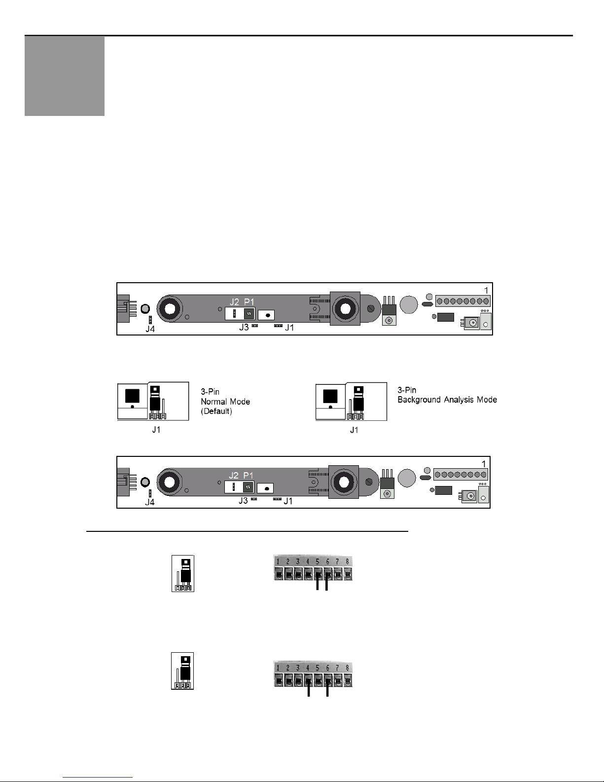
Background Analysis jumper set to ‘Normal Mode’ (see page 5).
a. Power the sensors with 12 – 24 VAC/VDC ±10%. LED status should reflect what was configured for the relay output
(see page 6)
b. Use a white, gray, or black piece of cardboard about 8" x 11" and hold it as shown in the diagram in step 2 of this
section (previous page).
c. Move the cardboard from the floor upward until it is detected. This will determine the height of the inactive area (B
distance).
d. Measure the height at which the cardboard was detected.
e. If this height does not fall between 12" – 16" above the floor or does not meet your requirements, an adjustment must
be made to the detection distance. One notch of the distance adjustment corresponds to approximately 4".
- If Zone B is too high, turn the distance adjustment clockwise to increase the detection distance and decrease
Zone B.
- If Zone B is too low, turn the distance adjustment counter-clockwise to decrease the detection distance.
Per current ANSI A156.10, 156.27 the detection zone must be within 28” of the floor. Ideally, each detector should
be adjusted so that detection occurs at 12” – 16” above the floor. Less than 12” of Zone B may result in occasional
false triggering of the sensor.
f. Once all sensors have been adjusted, activate the door several times and allow it to go through a full cycle each time.
Ensure that no false triggering is occurring, as would be indicated by the door re-cycling or stopping by itself at any
point of travel.
g. Ensure compliance of all applicable safety standards (i.e. ANSI A156.10, 156.27).
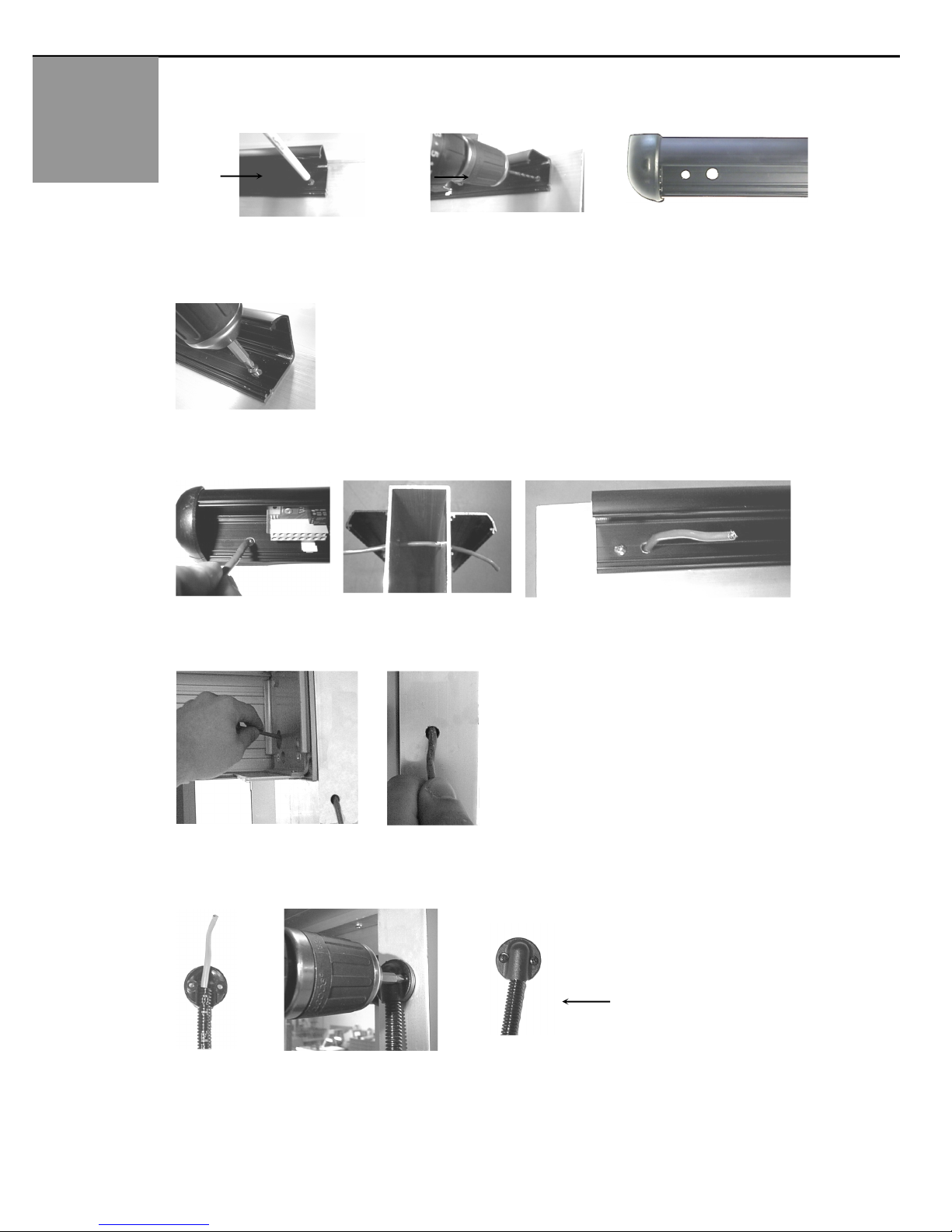
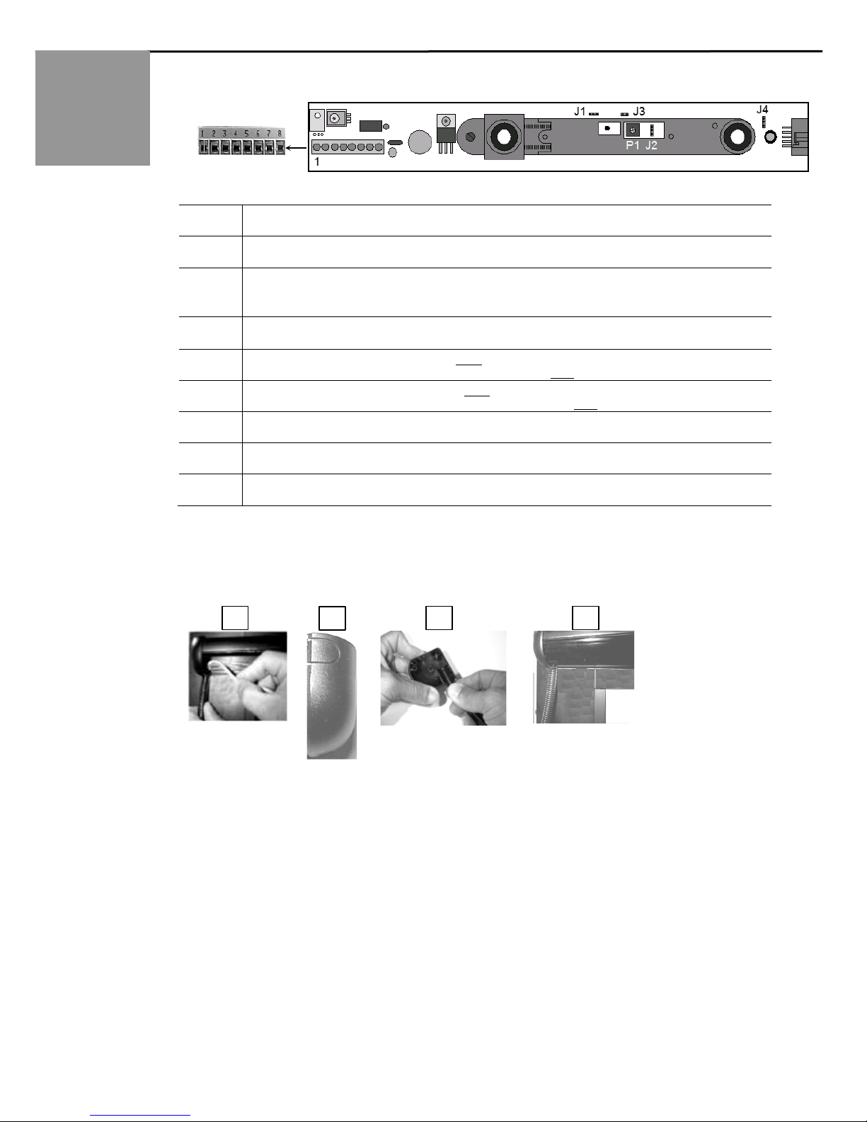
h. Install all remaining covers, endcaps, screws, etc.
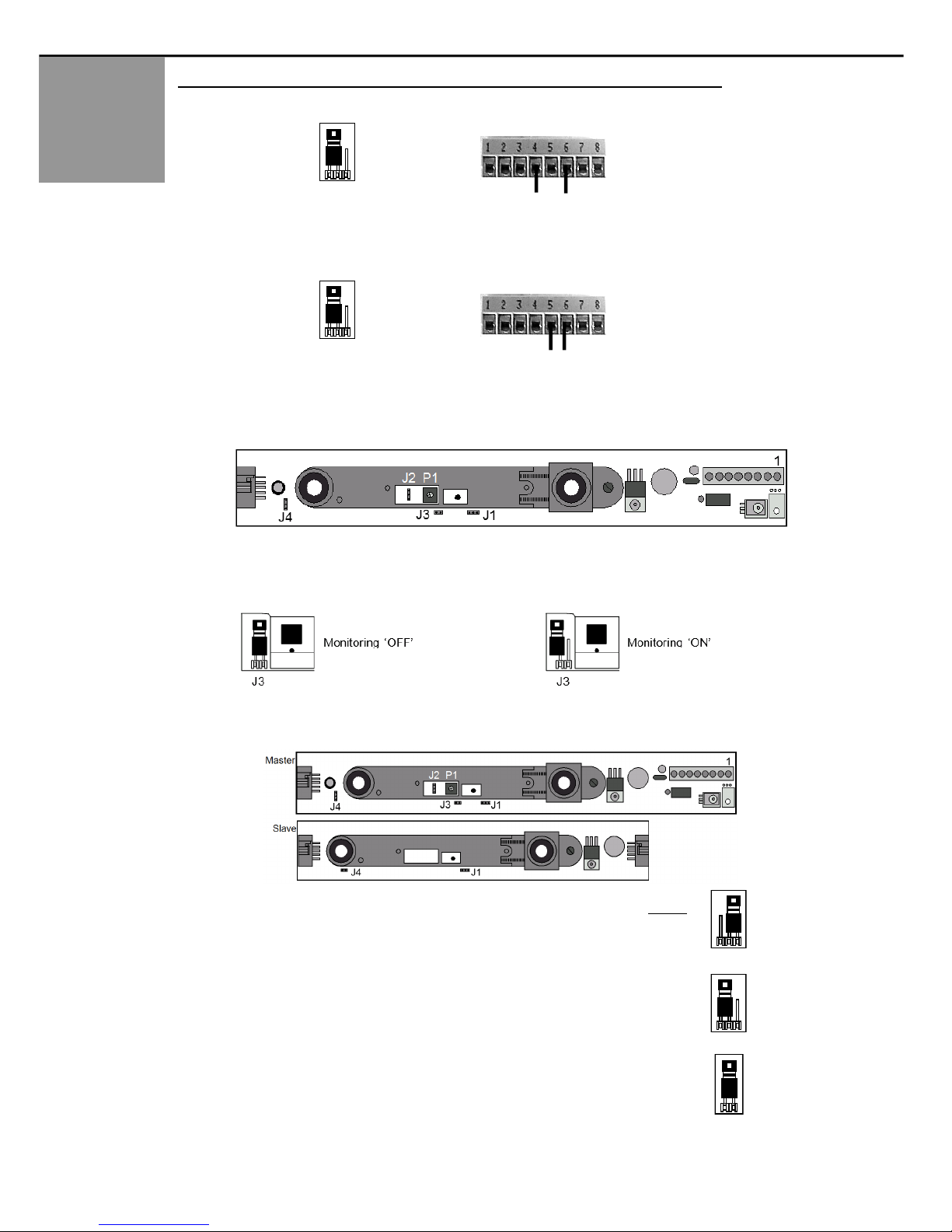
When using monitoring and non-monitoring modules in the same chain, observe the following rules:
• Non-monitoring Master modules CANNOT be used with monitoring Slave modules.
• All other combinations will work; however, for a system to utilize monitoring, all modules must be monitoring modules
PROBLEM
POSSIBLE CAUSE
CORECTIVE ACTION
SuperScan-T does not work
at all.
No LED indications.
Faulty power supply
Faulty connections
Power supply must be 12 – 24 VAC/VDC ±10%.
Check for this power at terminals 7 and 8 of the affected
SuperScan-T module.
SuperScan-T output appears
to be working opposite of
what is expected.
Relay output may be configured
improperly
Observe the LED indications on the affected modules to help
determine status.
Door stops by itself before
reaching the full-open
position.
Safety-side SuperScan-T may be
seeing an adjacent wall or rail behind
the door near the open position
Observe the LED status on safety side of door. Find the
SuperScan-T module that is being falsely triggered. Check
for:
ü Proper detection angle
ü Detection range adjustment
SuperScan-T may need to be inhibited at a specific point of
door travel at the safety side for proper operation. Refer to
the terminal connections on page 4.
Activation or safety is being
held triggered.
SuperScan-T detection module may
be seeing the floor or unwanted
object near door
Reduce the detection range on the affected module(s).
Detection should occur at 12” to 16” above the floor. Refer to
step 3 in “Mechanical Adjustments – Positioning & Angling
Modules” (above).
Erratic detection behavior is
occurring throughout the
door’s opening and closing
cycle.
Possible faulty wiring at door transfer
location
Using a multi-meter, check each wire for continuity at the
transfer location. Move the wires around during testing to help
locate any breaks. Replace faulty wiring as necessary.
Detection Distance Adjustment
MONITORING &
NON-MONITORING
COMPATIBILITY
MECHANICAL
ADJUSTMENTS
POSITIONING AND
ANGLING THE
MODULES
TROUBLE-
SHOOTING

75.5911.02 20180226 Page 9 of 9
Upon completion of the installation or service work, at a minimum, perform a daily safety check in accordance with the minimum inspection guidelines
provided by AAADM. Provide each equipment owner with an owner’s manual that includes a daily safety checklist and contains, at a minimum, the
information recommended by AAADM. Offer an information session with the equipment owner explaining how to perform daily inspections and point
out the location of power/operation switches to disable the equipment if a compliance issue is noted. The equipment should be inspected annually in accordance with the
minimum inspection guidelines. A safety check that includes, at a minimum, the items listed on the safety information label must be performed during each service call. If
you are not an AAADM certified inspector, BEA strongly recommends you have an AAADM certified inspector perform an AAADM inspection and place a valid inspection
sticker below the safety information label prior to putting the equipment into operation.
Tech Support: 1-800-407-4545 | Customer Service: 1-800-523-2462 | General Tech Questions: Tech_Services@beainc.com | Tech Docs: www.BEAinc.com
PN: 10SSQD
Quick Disconnect
Cable
PN: 10REL24V
Isolation Relay
PN: 10BR3
Interface module
ACCESSORIES
Other manuals for SUPERSCAN-T
1
Table of contents
Other BEA Accessories manuals
Popular Accessories manuals by other brands

SICK
SICK WLA26 Series operating instructions

nologo
nologo ZOOM-Z3E quick start guide

ROSE DISPLAYS
ROSE DISPLAYS ANOGOTCHA SQUARE WITH CABLE CLIP AND CABLE AND... manual

PCB Piezotronics
PCB Piezotronics IMI SENSORS EX642A12 Installation and operating manual

SOMFY
SOMFY 2401150 installation guide

Linptech
Linptech G4 user manual