Installation and Technical Information
BEGA
Accessories
Please refer to the appropriate
accessory installation sheet for
further instruction when applicable.
Replacement Parts
Relamping/Maintenance
No relamping required.
Anchorage 79 818
Description
Consult Factory
Part No
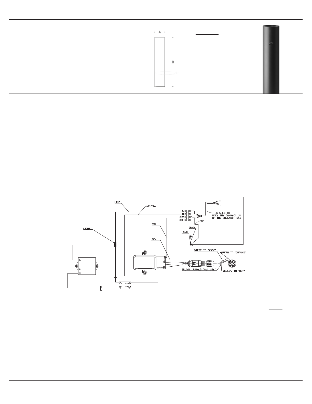
Bollard Tube with integrated motion sensor 99 658
Tools Required:
5mm hex key
Drill
Special tool (provided)
Protection Class: IP 65
Weight: 18.7 lbs
99 658 Function of the motion sensor:
Note: The plug part of the motion and light sensor must be plugged
into the plug-in device at the control gear box as far as it will go before
you switch on the power supply.
1. The sensor module is in the device box on the mounting bracket.
2. Open the device box.
3. When main voltage is turned on, the green LED will light up. The red
LED will be OFF in this case.
4. If the motion sensor is not connected correctly, the red LED will blink.
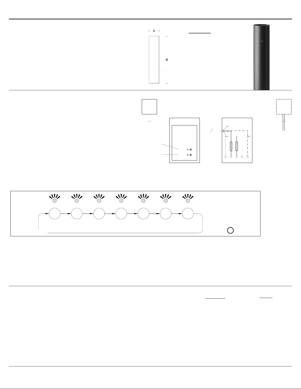
99 658 Time setting:
Note: DIP switch 1 is “OFF”
1. “T2” button can be used to set the holding time of the motion sensor.
Factory setting is 600 s.
2. See diagram below:
Dimensions
A: 7-1/2“
B: 32“
Einstellung der Haltezeit:
(DIP-Schalter 1 in Position "OFF")
Durch Bewegung im Erfassungsbereich
schaltet der Bewegungssensor die Leuchte mit
einer denierten Haltezeit ein.
Mit dem Taster T2 kann die Haltezeit
(Nachlaufzeit) des Bewegungssensors
eingestellt werden. Diese gibt an, wie lange
der Relaiskontakt eingeschaltet bleiben soll,
nachdem keine Bewegung mehr erkannt
wurde. Standardmäßig ist die Haltezeit 6 (900 s)
ausgewählt.
Wird der Taster T2 kurz gedrückt, wird die
nächste Haltezeit ausgewählt, die LED-Anzeige
blinkt zur Bestätigung (s. Abb.).
Die Auswahl der nächsten Haltezeit
sollte immer erst nach Ablauf der
Bestätigungsanzeige durchgeführt werden.
Nach Erreichen der höchsten Stufe beginnt die
Stufeneinstellung wieder mit Stufe 1.
Setting of dwell time:
(DIP Switch 1 in position "OFF")
By moving within the detection range the
motion sensor switches on the luminaire with a
dened dwell time.
Pushbutton T2 can be used to set the holding
time (overshoot time) of the motion sensor. This
denes how long the relay contact remains
active after the last movement was detected.
Dwell time 6 (900 s) is selected as standard.
When pushbutton T2 is pressed briey, the
next dwell time will be selected and the LED
indicator will blink in conrmation (see the
illustration).
The next dwell time should only be selected
when the conrmation indicator has stopped
ashing.
After reaching the highest level, the level setting
begins with "Level 1".
Réglage de temps de maintien:
(Interrupteur DIP 1 en position "OFF")
Au moindre mouvement dans la zone de
détection, le détecteur de mouvements active
le luminaire avec un temps de maintien déni.
La touche T2 permet de régler le temps de
maintien (temporisation) du détecteur de
mouvements. Cette durée est le temps pendant
lequel le contact de relais reste actif après la
dernière détection de mouvement.
La temporisation 6 (900 s) est sélectionnée en
standard.
Un bref appui sur la touche T2 permet
de sélectionner la temporisation suivante,
l’afchage LED clignote jusqu’à conrmation
(voir illustration).
Sélectionnez toujours la temporisation suivante
après l’afchage de conrmation.
Une fois le niveau maximal atteint, le réglage
reprend à partir du «niveau 1 ».
Setting of dwell time
Réglage de temps de maintien
TASTER
BUTTON
BOUTON T2
1
15 s
1x
60 s 180 s 300 s 600 s
2
2x
3
3x
4
4x
5
5x
6
6x 7x
900 s
7
1800 s
Stufe
Step
Niveau
Anzahl Blinken
Number of flashes
Nombre scintellement
Haltezeit
Dwell time
Temps de maintien
Einstellung der Haltezeit
LED an
LED on
LED allumée
Rote LED
Red LED
LED rouge
0,5 s 0,5 s
0,5 s 0,5 s
2 s
LED aus
LED off
LED éteinte 11 22 33
Taster T2 wird gedrückt
Pushbutton T2 is pressed
Le bouton-poussoir T2 est actionné
Einstellung der Helligkeitsstufe:
Der Lichtsensor kann individuell mit den
Helligkeitsstufen auf den gewünschten
Schwellwert eingestellt werden – Taste T1.
Standardmäßig ist die Stufe 1 (Tageslicht)
ausgewählt.
Wird der Taster T1 kurz gedrückt, wird die
nächste Helligkeitsstufe ausgewählt, die LED-
Anzeige blinkt zur Bestätigung (s. Abb.).
Die Auswahl der nächsten Helligkeitsstufe
sollte immer erst nach Ablauf der
Bestätigungsanzeige durchgeführt werden.
Nach Erreichen der höchsten Stufe beginnt die
Stufeneinstellung wieder mit Stufe 1.
Im Einlern-Modus wird der aktuelle
Helligkeitswert, den der Sensor sieht, als
Schwellwert abgespeichert.
Setting of brightness level:
The light sensor can be set individually with the
brightness levels on the ambient brightness -
Press the button T1.
Step 1 (Daylight) is selected as standard.
When pushbutton T1 is pressed briey, the
next brightness level will be selected and the
LED indicator will blink in conrmation (see the
illustration).
After reaching the highest level, the level setting
begins with "Level 1".
The next brightness level should only be
selected when the conrmation indicator has
stopped ashing.
In the teaching mode, the brightness value
currently seen by the sensor is saved as the
threshold value.
Réglage de luminosité:
Le capteur de luminosité peut être réglé en
fonction de la luminosité ambiante à l'aide des
différents niveaux de luminosité - bouton T1.
Le niveau 1 (Lumière de jour) est sélectionnée
en standard.
Un bref appui sur la touche T1 permet de
sélectionner la luminosité suivante, l’afchage
LED clignote jusqu’à conrmation (voir
illustration).
Une fois le niveau maximal atteint, le réglage
reprend à partir du «niveau 1 ».
Sélectionnez toujours la luminosité suivante
après l’afchage de conrmation.
En mode apprentissage, la valeur de luminosité
actuelle mesurée par le capteur est enregistrée
comme valeur de seuil.
1x 2x 3x 4x 5x 6x
Stufe
Step
Niveau
Anzahl Blinken
Number of flashes
Nombre scintellement
123 4 56
Tageslicht 300 lx 150 lx Dämmerung Dunkelheit Einlernen
Daylight 300 lx 150 lx Twilight Darkness Teach-in
Lumière de jour 300 lx 150 lx Crépuscule Obscurité Configuration
Setting of brightness
Réglage de luminosité
TASTER
BUTTON
BOUTON T1
Einstellung der Helligkeit
Helligkeit
Brightness
Luminosité
LED an
LED on
LED allumée
Grüne LED leuchtet dauerhaft
(Helligkeitsstufe 2)
Green LED is again on continuously
(brightness level 2)
La LED verte s’allume de nouveau en
permanence (luminosité 2)
0,5 s 0,5 s 0,5 s
0,5 s 0,5 s 0,5 s
Grüne LED leuchtet wieder dauerhaft
(Helligkeitsstufe 3)
Green LED is again on continuously
(brightness level 3)
La LED verte s’allume de nouveau en
permanence (luminosité 3)
Taster T1 wird gedrückt
Pushbutton T1 is pressed
Le bouton-poussoir T1 est actionné
LED aus
LED off
LED éteinte 11 22 33
Die Montageplatte mit Anschlusskasten so
montieren, dass der Gerätekasten von der
Montagetür zugänglich ist.
Die genaue Ausrichtung der Leuchte erfolgt
durch Drehung im Fußpunkt der Leuchte.
Verschluss der Montagetür entriegeln und
Montagetür entnehmen.
Anschlusskasten öffnen.
Erdkabel in den Anschlusskasten führen.
Schutzleiterverbindung herstellen und
elektrischen Anschluss vornehmen.
Install the mounting plate with connection
box in such a way that the control gear box is
accessible via the access door.
The exact alignment of the luminaire is
achieved by turning the luminaire in the base
section.
Unlock fastener of the installation door and
remove it.
Open the connection box.
Lead the mains supply cable into the
connection box. Make earth conductor
connection and electrical connection.
Installer la platine de xation avec la boîte
de connexion, de sorte à pouvoir accéder
au coffret d’alimentation depuis la porte de
montage.
La direction du faisceau peut être orientée
de façon précise en tournant le luminaire
sur sa platine.
Déverrouiller le dispositif de fermeture
et retirer la porte de montage.
Ouvrir la boîte de connexion.
Introduire le câble réseau dans la boîte de
connexion à travers l'entrée de câble. Mettre à
la terre et procéder au raccordement électrique.
Pollerleuchtenkopf in das Pollerleuchtenrohr
einsetzen, rechtsherum bis zum Anschlag
drehen, ggf. ausrichten und mit seitlicher
Innensechskantschraube festsetzen.
Leuchtenanschlussleitung durch die obere
Leitungseinführung in den Anschlusskasten
führen. Schutzleiterverbindung herstellen und
elektrischen Anschluss vornehmen.
Dabei auf richtige Belegung der Anschluss-
leitung achten. Anschluss der braunen Ader
an der losen Klemme (L'). Zur digitalen
Ansteuerung des Pollerleuchtenkopfes sind
die beiden losen, mit DALI gekennzeichneten
Steckklemmen zu verwenden.
Bei Nichtbelegung dieser Adern wird die
Leuchte mit voller Lichtleistung betrieben.
Anschlusskasten schließen.
Insert bollard head into bollard tube and turn it
clockwise as far as it will go, adjust if necessary
and x with lateral hexagon socket head screw.
Lead the luminaire connecting cable through
the compression nipple into the connection
box. Make earth conductor connection and
electrical connection.
Note correct conguration of the mains supply
cable. The brown wire is connected at the
loose connection (L').
For digital control of the bollard head please
use the two loose DALI plug-in terminals.
In case these leads are not used the luminaire
will be operated at full light output.
Close the connection box.
Installer la tête de la balise dans le support
de la balise et tourner vers la droite jusqu’à la
butée, ajuster le cas échéant puis xer avec la
vis à six pans creux latérale.
Introduire le câble des luminaires dans la boîte
de connexion à travers le nipple d'étanchéité
supérieur. Mettre à la terre et procéder au
raccordement électrique.
Veiller au bon adressage du câble de
raccordement. La gaine marron doit être
raccordée au bornier non xé (L'). Pour
pilotage numérique utiliser les 2 connecteurs
embrochables lâches, marqués (DALI).
Si les ls ne sont pas raccordés, le luminaire
fonctionne sur la puissance maximale.
Fermer la boîte de connexion.
Das Steckerteil vom Bewegungs- und
Lichtsensor muss vor dem Einschalten der
Spannungsversorgung in die Steckvorrichtung
am Gerätekasten eingesteckt werden.
The plug part of the motion and light sensor
must be plugged into the plug-in device at the
control gear box as far as it will go before you
switch on the power supply.
Le connecteur du capteur de luminosité et de
mouvement doit être branché au connecteur
du coffret d’alimentation avant la mise sous
tension de l’alimentation.
Sensormodul
Sensor module
Module du capteur
LED 2:
rot · red · rouge
LED 1:
grün · green · verte
Bewegungssensor und Lichtsensor
Motion sensor and light sensor
Détecteur de mouvement et capteur de luminosité
4
Gerätekasten
Device box
Coffret pour appareillage
Anschlusskasten
Connection box
Boîte de connexion
LED 2 T2
N
L'
L1 L2 L3
LED 1 T1
Leuchtenkopf
Luminaire head
Tête du luminaire
5
4
L N DADA
Funktionsweise des Bewegungs- und
Lichtsensors:
Das Sensormodul bendet sich im Geräte-
kasten auf dem Montagebügel.
Gerätekasten öffnen.
Wenn am Sensormodul Netzspannung anliegt,
leuchtet die grüne LED.
Die rote LED ist in diesem Fall ausgeschaltet.
Nach ca. 4 Sekunden startet das Sensormodul
die Einbindung des Bewegungs- und
Lichtsensors. Wurden die Sensoren erfolgreich
erkannt, leuchtet nach ca.15 Sekunden die
grüne LED. Ein nicht erkannter bzw. nicht
angeschlossener Bewegungs- und Lichtsensor
wird durch dauerhaftes Blinken (2x/sec) der
roten LED angezeigt.
Function of the motion sensor and light
sensor:
The sensor module is in the device box on the
mounting bracket.
Open the device box.
When mains voltage is applied to the sensor
module, the green LED will light up.
The red LED is OFF in this case.
The sensor module will start integrating the
motion sensor after approx. 4 seconds. If the
motion sensor is detected successfully, the
green LED will become lit after approx. 15
seconds.
A non-detected or non-connected motion
sensor will be indicated by continuous blinking
(2x per second) of the red LED.
Fonction du détecteur de mouvement et
capteur de lumoniseté:
Le module capteur se trouve dans le coffret
pour appareillage sur l’étrier de xation.
Ouvrir le coffret pour appareillage.
Lorsque le module capteur est sous tension, la
LED verte s’allume.
Dans ce cas, la LED rouge est éteinte.
Après 4 secondes environ, le module capteur
démarre la connexion du détecteur de
mouvement. Si le détecteur de mouvement a
été détecté avec succès, la LED verte s’allume
au terme de 15 secondes environ.
En cas de non-détection ou de non-connexion
d’un détecteur de mouvement, la LED rouge
clignote en continu (2 fois par seconde).
In the interest of product improvement, BEGA reserves the right to make technical changes without notice.
BEGA 1000 Bega Way, Carpinteria, CA 93013 (805)684-0533 Fax (805)566-9474 www.bega-us.com © Copyright BEGA-US 2019 99 658
03/26/2019
3 of 4