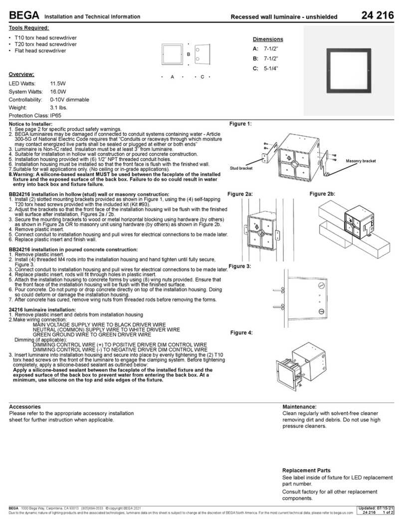
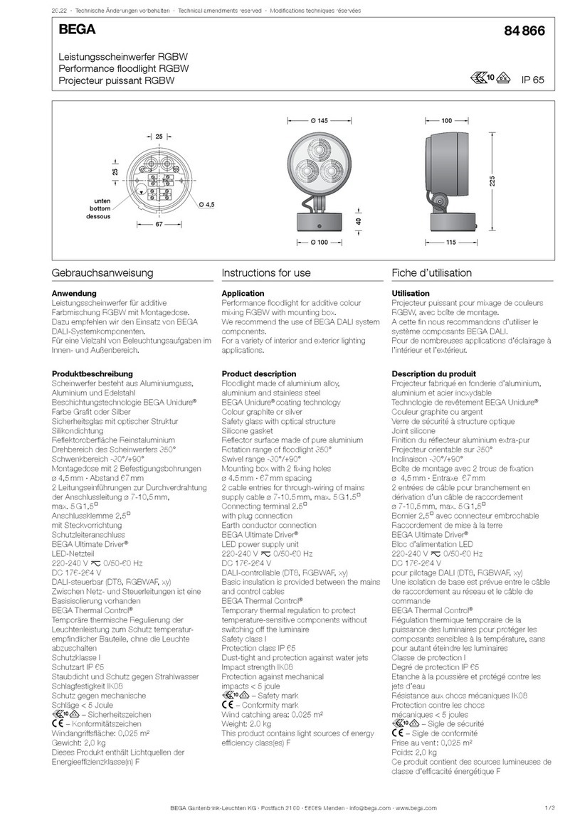
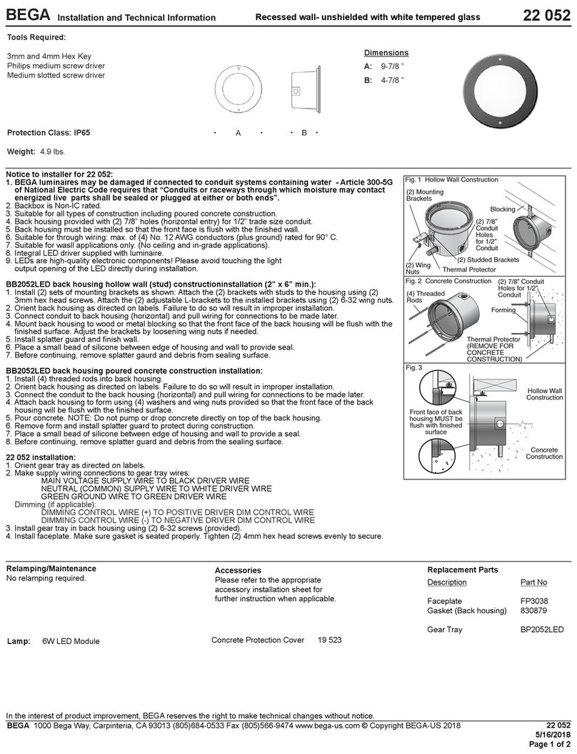
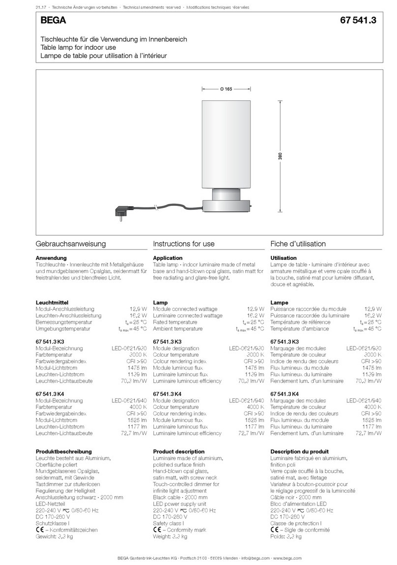
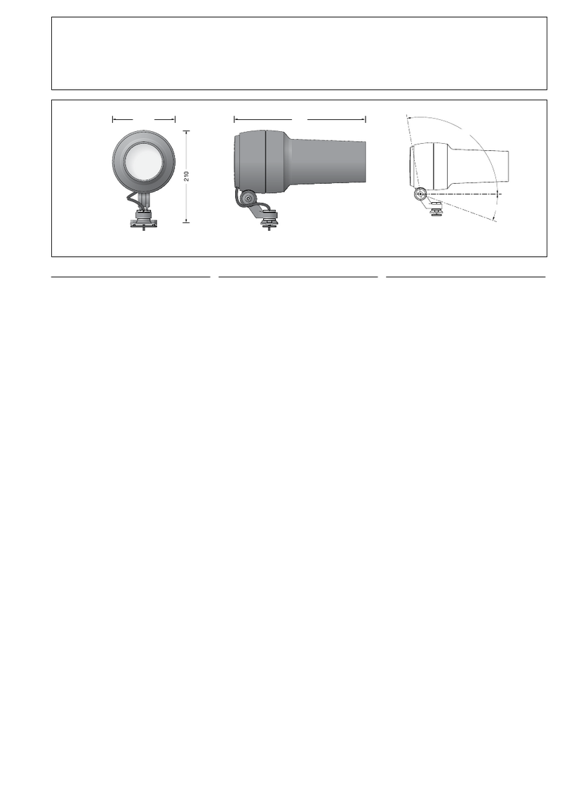
BEGA 85 046 User manual

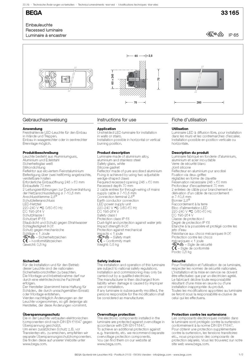
BEGA Gantenbrink-Leuchten KG · Postfach 31 60 · 58689 Menden · info@bega.com · www.bega.com 1/4
c
é
26.22 · Technische Änderungen vorbehalten · Technical amendments reserved · Modications techniques réservées
IP 54
!
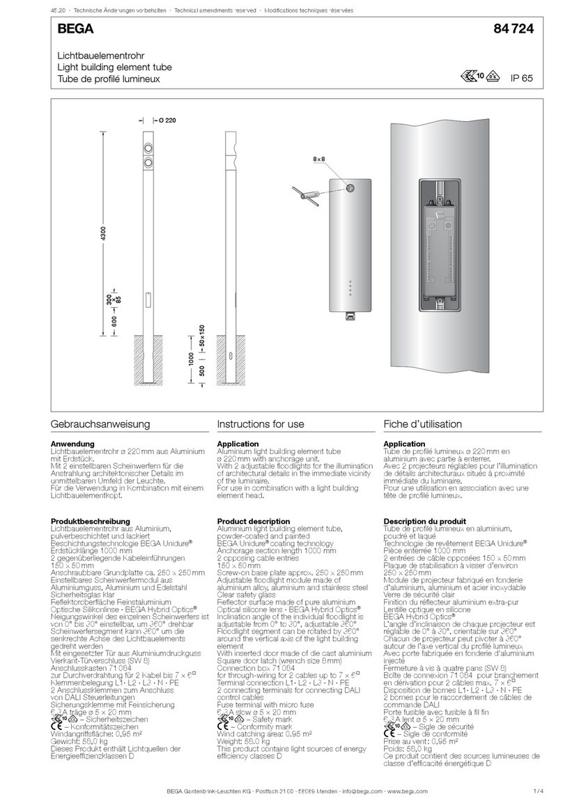
Lichtmast mit Lademodul
Luminaire pole with charging module
Mât avec module de chargement
85 046
8×8
□ 200
□ 200
Ø 340
Ø 20
22
Ø 76
100
800
5000
660660
235235
74 074 0965965
13501350
Montageanleitung Installation instructions Notice de montage
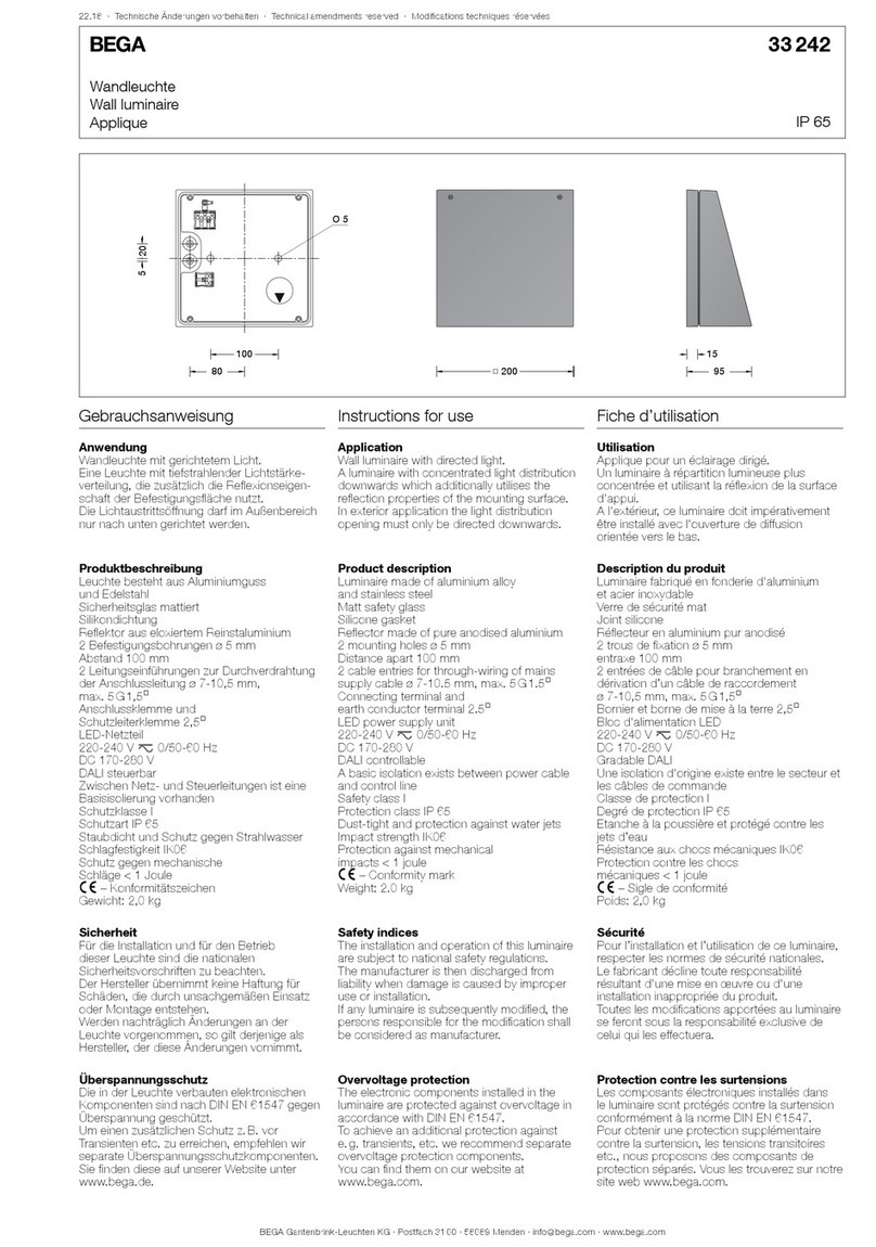
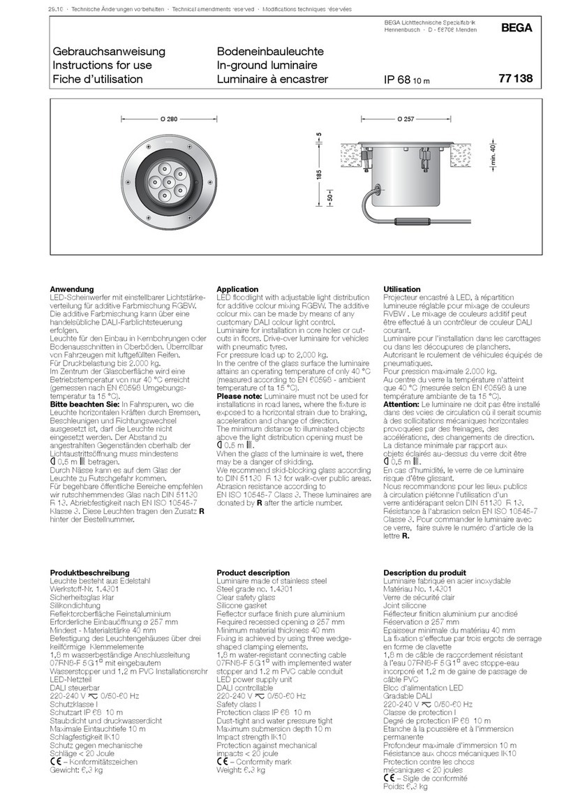
Anwendung
Aluminium-Lichtmast mit Fußplatte und
eingebauter Ladeeinheit in besonders
robuster Ausführung für den öffentlichen und
halböffentlichen Bereich.
Eine ausführliche Anleitung zur Inbetriebnahme
der Ladeeinheit nden sie in der separat
beiliegenden Bedienungsanleitung.
Application
Aluminium pole with base plate and integrated
charging unit with particularly robust design for
private and semi-public areas.
A detailed guide for commissioning the
charging unit can be found in the operating
instructions enclosed separately.
Utilisation
Mât en aluminium sur platine avec unité
de charge intégrée dans une version
particulièrement robuste pour l’usage privé et
semi-public.
Vous trouverez des instructions détaillées sur
la mise en service de l’unité de charge dans le
mode d’emploi fourni à part.
Sicherheit
Für die Installation und für den Betrieb
dieser Ladeeinheit sind die nationalen
Sicherheitsvorschriften zu beachten.
Die Montage und Inbetriebnahme darf nur
durch eine Elektrofachkraft erfolgen.
Der Hersteller übernimmt keine Haftung für
Schäden, die durch unsachgemäßen Einsatz
oder Montage entstehen.
Werden nachträglich Änderungen an dieser
Ladeeinheit vorgenommen, so gilt derjenige als
Hersteller, der diese Änderungen vornimmt.
Safety
The installation and operation of this charging
unit are subject to national safety regulations.
Installation and commissioning may only be
carried out by a qualied electrician.
The manufacturer accepts no liability for
damage caused by improper use or installation.
Should the charging unit be subsequently
modied, the persons responsible for
the modication shall be considered the
manufacturer.
Sécurité
Pour l’installation et l’utilisation de cette unité
de charge, respecter les normes de sécurité
nationales.
L’installation et la mise en service ne doivent
être effectuées que par un électricien agréé.
Le fabricant décline toute responsabilité pour
les dommages résultant d’une utilisation ou
d’une installation inappropriée du produit.
Si des modications sont ultérieurement
apportées à cette unité de charge, l’intervenant
qui les aura effectuées est alors considéré
comme le fabricant.
Produkteigenschaften
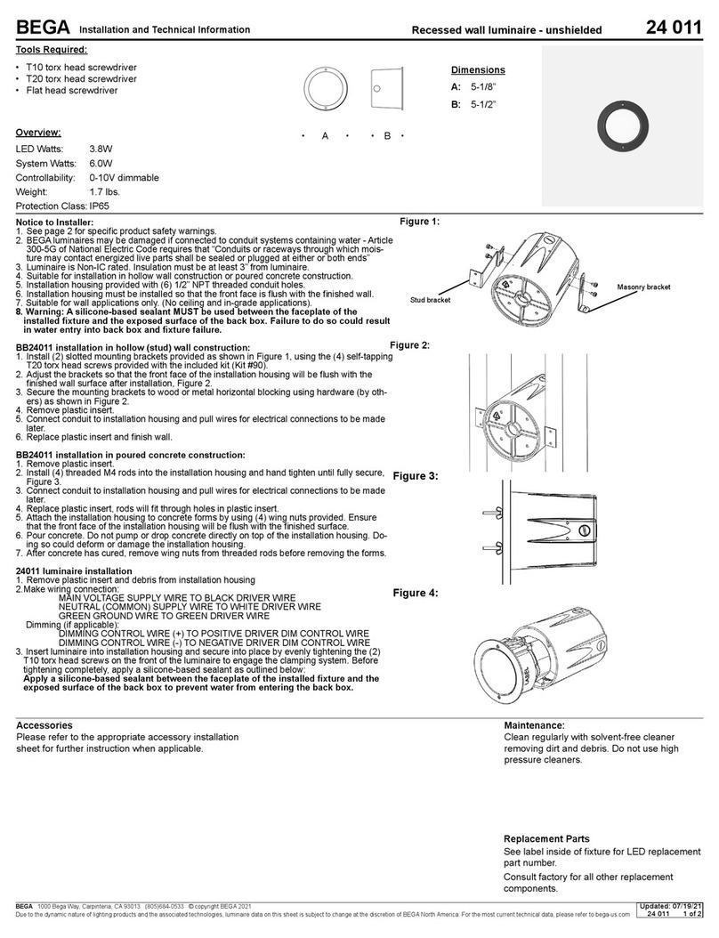
Widerstand gegen horizontale Lasten:
vref,0 = 32 m/s
Geländekategorie: 1
nach DIN EN 1991-1-4
Leuchten mit einem Gewicht bis 40kg
und einer Windangriffsäche max. 0,45m²
Verformungsklasse: 1 – Sicherheitsklasse: A
nach DIN EN 40-3-3
Verhalten bei Fahrzeuganprall nach
DIN EN 12767 (passive Sicherheit): Klasse 0
Product characteristics
Resistance against horizontal loads
vref,0 = 32 m/s
Terrain category: 1
in accordance with DIN EN 1991-1-4
Luminaires with a maximum weight of 40kg
for a wind catching area max. 0.45m²
Deformation class: 1 – Safety class: A
in accordance with DIN EN 40-3-3
Properties in case of vehicle impact
(passive safety): class 0 in accordance with
DIN EN 12767
Caractéristiques de produits
Résistance aux charges horizontales:
vref,0 = 32 m/s
Catégorie de terrain: 1
selon DIN EN 1991-1-4
Luminaires avec un poids jusqu'à: 40kg
et une surface de prise au vent: 0,45m²
Classe de déformation 1 –
Classe de sécurité A selon DIN EN 40-3-3
Performance en cas d’impact d’un véhicule
(sécurité passive): Classe 0

BEGA Gantenbrink-Leuchten KG · Postfach 31 60 · 58689 Menden · info@bega.com · www.bega.com
2/4
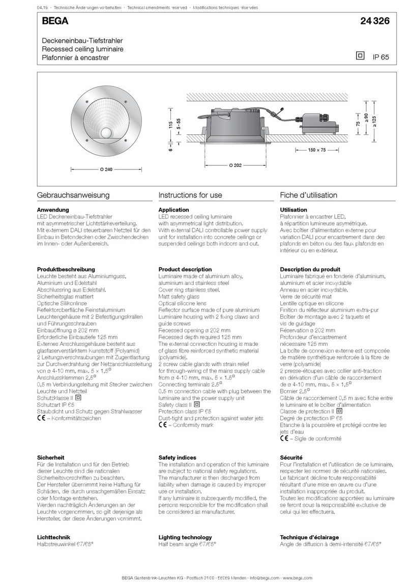
Produktbeschreibung
Mast aus Aluminium und Aluminiumguss,
pulverbeschichtet und lackiert
Beschichtungstechnologie BEGA Unidure®
Mastzopf ø 76mm
Fußplatte mit 4 Befestigungsbohrungen
zur Montage auf ein Fundament oder
Erdstück (Ergänzungsteil 70 899)
Intergrierte Ladeeinheit mit Anschlussleitung
H07RN-F 5G 6@
Leitungslänge 2m
Ethernet-Datenkabel Cat6A mit SteckerRJ45
Länge 1,5m
Buchsenteil zum Anschluss der bauseitigen
Datenleitung
Integrierte DC-Fehlerstromerkennung 6mA
Absicherung, Überspannungsschutz und RCD-
Schutzschalter sind bauseits vorzusehen
Spannung 230/400 VAC,50 Hz
(1- oder 3-phasig)
zum Anschluss an ein 230/400 V
Drehstrom-Vierleitersystem
Strom 16/32A
Lastschütz 4-polig, 40A
Steuersicherung 1-polig,B6
DC-Auslösestrom I∆DC 0,006A
Für Netzformen TN und TT
Steckdose Typ 2 nach EN 62196 mit
integrierter Statusbeleuchtung
Ladeleistung 3,7–22kW
MID-konformer Energiezähler (kWh)
Eichrechtskonform gemäß MessEV
Integration in Last- und Lademenagement
möglich
Autorisierung über RFID-Kartenleser
Für die Umsetzung einer Ladestation gemäß
Ladesäulenverordnung ist eine Kopplung
mit dem BEGA Bezahlterminal für gängige
Zahlungsmittel möglich – siehe Ergänzungsteile
Kommunikation zum Backend per LTE über
OCPP1.6JSON
Betriebstemperaturbereich: -25°C bis 45°C
Mit eingesetzter Tür aus Aluminiumdruckguss
Vierkant-Türverschluss (SW8)
Anschlusskasten mit Leitungseinführungen
zum Durchverdrahten der Anschlussleitung
ø 2-14 mm, max. 2,5@
für den elektrischen Anschluss des
Leuchtenkopfes
C-Schiene mit 2 Schiebemuttern M6 zur
Aufnahme eines bauseitigen Anschlusskasten
nach DIN43628/VDE0660 zum Anschluss
der Ladeeinheit
Schutzart IP65
Staubdicht und Schutz gegen Strahlwasser
Steckdose (mit geschlossenem Klappdeckel)
Schutzart IP 54
Staubgeschützt und Schutz gegen
Spritzwasser
Schlagfestigkeit IK10
Schutz gegen mechanische
Schläge < 20 Joule
c0780 – Leistungserklärung
Windangriffsäche:0,84m²
Gewicht: 54,0 kg
Product description
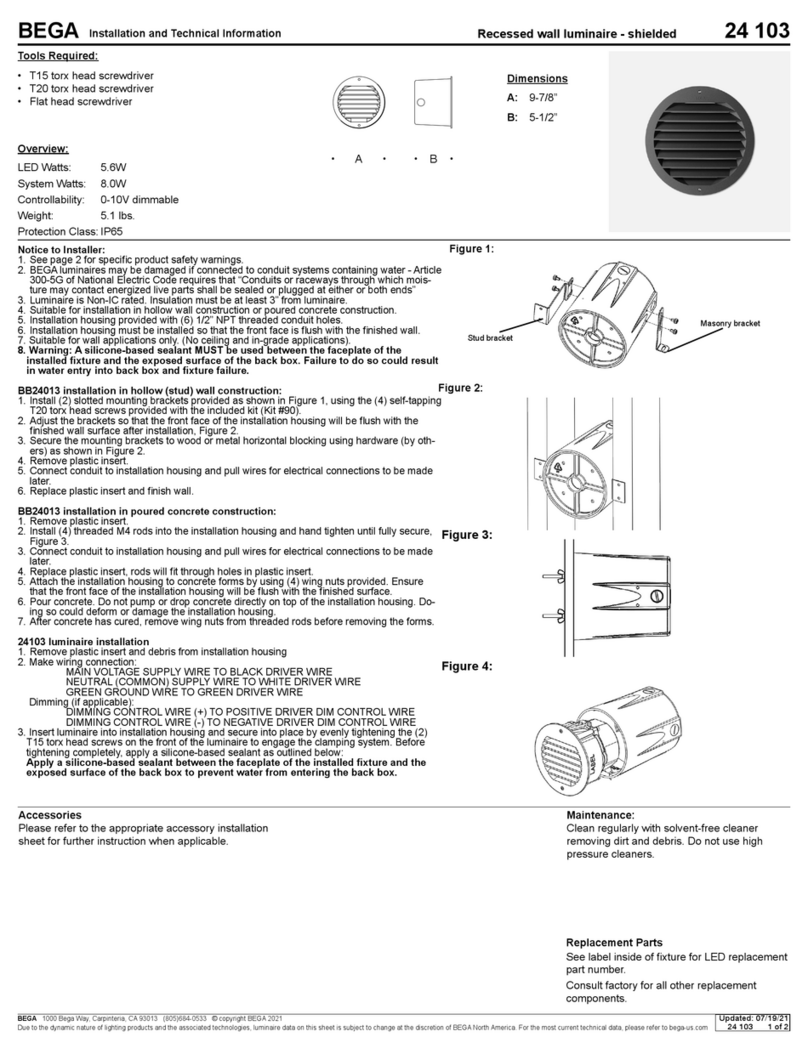
Luminaire pole made of aluminium and
aluminium alloy , powder coated and lacquered
BEGA Unidure® coating technology
Pole top ø 76mm
Base plate with 4 xing holes
for installation on a foundation or
anchorage unit (accessory 70 899)
Integrated charging unit with connecting cable
H07RN-F 5G 6@
Cable length 2m
Ethernet data cable Cat 6A with plug RJ45
Length 1.5m
Jack part for connection to on-site data cable
Integrated DC fault current detection 6mA
Fuse protection, overvoltage protection and
RCD protective switch must be provided by the
customer
Voltage 230/400 VAC,50 Hz
(1 or 3 phases)
for connection to 230/400 V
four-wire system
Current 16/32A
Load contactor 4-pole, 40 A
Control fuse 1-pole, B6
DC trigger current I∆DC 0.006A
For TN and TT mains systems
Socket type 2 pursuant to EN 62196 with
integrated status light
Charging capacity 3.7–22 kW
MID-compliant energy meter (kWh)
Compliant with calibration regulations pursuant
to MessEV
Integration into load and charging management
possible
Authorisation via RFID card reader
For the implementation of a charging station
pursuant to the Charging Columns Ordinance,
coupling with the BEGA payment terminal is
possible for common payment methods – see
accessories
Communication with backend via LTE using
OCPP1.6JSON
Operating temperature range: -25°C to 45°C
With inserted door made of die cast aluminium
Square door latch (wrench size8 mm)
Connection box with cable entries for
through-wiring of mains supply cable
ø 2-14 mm, max. 2.5@
for electrical connection of the luminaire head
C-rail with 2 M6 sliding nuts to accommodate
an on-site connection box in accordance with
DIN43628/VDE0660 for the connection of
the charging unit
Protection class IP 65
Dust-tight and protected against water jets
Socket (with closed ap)
Protection class IP 54
Protection against harmful dust deposits and
splash water
Impact strength IK10
Protection against mechanical
impacts < 20 joule
c0780 – Declaration of performance
Wind catching area:0.84m²
Weight: 54.0 kg
Description du produit
Mât fabriqué en aluminium et fonderie d’alu,
surface poudrée et laquée
Technologie de revêtement BEGA Unidure®
Tête de mât ø 76mm
Platine avec 4 trous de xation pour
l’installation sur un massif de fondation ou
sur la pièce enterrée (Accessoire 70 899)
Unité de charge intégrée avec câble de
raccordement H07RN-F 5G6@
Longueur de câble 2m
Câble de données Ethernet Cat6A avec
cheRJ45
Longueur 1,5m
Partie femelle pour le raccordement de la ligne
de données sur site
Détection intégrée de courant de défaut CC
6mA
La protection de la ligne, la protection contre
les surtensions et le disjoncteur RCD doivent
être prévus sur le site.
Tension 230/400 VAC 50,50Hz
(monophasée ou triphasée)
pour la connection au 230/400 V
système à quatre ls
Intensité du courant 16/32 A
Contacteur de puissance 4pôles, 40A
Fusible du circuit de commande à 1 pôle,B6
Courant de déclenchement I∆DC 0,006A
Pour topologies du réseau TN et TT
Prise de courant type 2 conformément à
EN62196 avec éclairage d’état intégré
Capacité de charge 3,7–22kW
Compteur d’énergie conforme à MID (kWh)
Conforme à la législation sur l’étalonnage selon
MessEV
Intégration possible dans la gestion de la
charge et du chargement
Autorisation par lecteur de cartes RFID
Pour la mise en œuvre d’une station de
recharge conformément à la législation sur
les chargeurs, il est possible d’effectuer une
connexion pour les moyens de paiement
courants avec le terminal de paiement BEGA
(voir accessoires)
Communication avec le backend par réseau
LTE via OCPP1.6JSON
Température de service: de -25 °C à 45 °C
Avec porte fabriquée en fonderie d'aluminium
injecté
Fermeture à vis à quatre pans (SW8)
Boîte de connexion avec entrées de câble
pour branchement en dérivation de câble de
raccordement ø 2-14 mm, max. 2.5@
pour le raccordement électrique du tête de
luminaire
Rail C avec 2 écrous coulissants M6 destiné à
loger une boîte de connexion présente sur le
site conformément à DIN43628/VDE0660
pour le raccordement de l’unité de charge
Degré de protection IP65
Étanche à la poussière et protection contre les
jets d’eau
Prise de courant (avec clapet fermé)
Degré de protection IP 54
Protection contre la poussière et les projections
d’eau
Résistance aux chocs mécaniques IK10
Protection contre les chocs
mécaniques < 20 joules
c 0780 – Déclaration de performance
Prise au vent :0,84m²
Poids: 54,0 kg
Vor der Montage zu beachten:
Die Zuleitung für jede Ladeeinheit muss
über eine entsprechende Absicherung
mit Leitungsschutzschalter und
Fehlerstromschutzschalter verfügen.
Des Weiteren empfehlen wir die Verwendung
eines Überspannungsschutzes.
Für die elektrischen Verbindung ist ein
entsprechender Anschlusskasten erforderlich.
Hierzu empfehlen wir die Verwendung des
BEGA Anschlusskasten 71 306 mit integriertem
Fehlerstrom-Leitungsschutzschalter und
Überspannungsschutz (siehe Ergänzungsteile).
Prior to installation, please note:
The supply line for each charging unit must
have corresponding safeguards with automatic
cutout and residual current circuit breaker.
We also recommend the use of overvoltage
protection.
For the electrical connection, a corresponding
connection box is required.
For this purpose, we recommend using the
BEGA connection box 71 306 with integrated
residual current automatic cutout and
overvoltage protection (see accessories).
À respecter avant l’installation:
Le câble de chaque unité de charge doit
disposer d’une protection adéquate avec
disjoncteur de protection de ligne et disjoncteur
différentiel.
Nous conseillons en outre d’utiliser une
protection contre les surtensions.
Pour la connexion électrique, il faut la boîte de
connexion correspondante.
Nous vous conseillons à cet égard d’utiliser
la boîte de connexion 71 306 de BEGA avec
disjoncteur différentiel et protection contre
les surtensions intégré (se reporter aux
accessoires).

BEGA Gantenbrink-Leuchten KG · Postfach 31 60 · 58689 Menden · info@bega.com · www.bega.com 3/4
1000 × 1000
Erdreich · Soil · Terre
Sauberkeitsschicht · Sub-base
Couche d’assainissement
Drainage · Drainage · Drainage
BEGA 70 899
Beton · Concrete · Béton
1000 × 1000
700
700
verdichteter Boden
Compacted soil · Sol damé
800
Montage
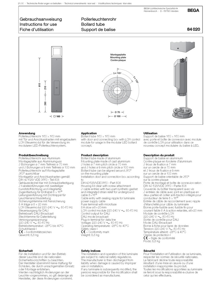
Der Mast ist je nach Einsatzart, Leuchtengröße
und Gewicht standsicher zu gründen.
Die Fundamentgröße ist abhängig von der
Topographie, Bodenbeschaffenheit und
Windbelastung und muss jeweils bauseits
bestimmt werden.
Dazu gilt die Norm DIN 1045.
Die obige beispielhafte Fundamentempfehlung
gilt für einen tragfähigen Baugrund.
Tür mit beiliegendem Vierkantschlüssel öffnen
und entnehmen.
Erdkabel in den Mast führen.
Mast auf Fundament oder Erdstück
(Ergänzungsteil 70 899) standsicher befestigen.
Das Befestigungsmaterial für die Montage auf
ein Fundament ist bauseits festzulegen und zu
stellen: z. B. Steinschrauben aus Edelstahl
M16 x 300 DIN 529.
Dabei auf bauaufsichtliche Zulassung achten.
Bitte beachten:
Feuchter Beton kann stark alkalisch sein und
darf nicht dauerhaft mit dem Mast in Kontakt
kommen.
Wir empfehlen den Montagebereich zu
drainieren und mit Isolieranstrich zu versehen.
Leuchte und Anschlusskasten montieren.
Hierzu die Gebrauchsanweisung der Leuchte
beachten.
Installation
Depending on the mode of application, the size
and weight of the luminiare the pole must be
rmly xed.
The size of the foundation depends on the
topography, condition of the soil and the wind
load and must be determined on site.
DIN1045 applies.
The above exemplary recommendation for
a foundation is applicable for a stable.
Open door with enclosed square spanner and
remove door.
Lead underground cable into the pole.
Fix pole stably on a foundation or an anchorage
unit (accessory 70 899).
The xing material for an installation on a
foundation must be determined and provided
by the customer: e.g. stone bolts made of
stainless steel M16 x 300 DIN 529.
Note authorization through supervision of
construction.
Please note:
Wet concrete can be very alkaline and must not
get into contact with the pole permanently.
We recommend to drain the mounting area and
to provide it with insulating paint.
Assemble luminaire and connection box.
Note the instructions for use of the luminaire.
Installation
Le mât doit être installé en tenant compte de
son utilisation, des dimensions et poids du
luminaire, de la prise au vent.
Le volume et les dimensions du massif béton
dépendent de la topographie, la pression
à fond de fouille du sol, de la zone de vent,
ainsi que des forces et des charges exercées
et doivent être individuellement dénis sur le
chantier.
La norme DIN1045 est alors applicable.
Le massif de fondation recommandé ci-dessus
est un exemple uniquement valable pour un
terrain à bâtir solide.
Déverrouiller et retirer la porte avec la clé jointe.
Introduire le câble réseau dans le mât. Fixer
solidement le mât sur le massif en béton ou sur
la pièce à enterrer (accessoire 70 899).
Les matériaux de xation pour la xation sur un
massif en béton doivent être dénis et fournis
sur le chantier: par exemple vis à scellement en
acier inoxydable M16 x 300 DIN 529.
Respecter les consignes de la maitrise
d'ouvrage.
Attention :
La laitance du béton peut être fortement
alcaline et ne doit pas être en contact durable
avec le mât. La surface où est installé le
luminaire doit être draînée et protégée par une
matière isolante. Installer le luminaire et la boîte
de montage - voir la che d'utilisation.
Für bauseitig vorgesehene Blitz- und
Überspannungsschutzmaßnahmen oder zum
Anschluss eines Potentialausgleichs, steht am
Fußpunkt des Mastes ein M10-Gewindeeinsatz
zur Verfügung.
Eine passende Befestigungsschraube mit
Federring und Unterlegscheibe bendet sich im
Beipack der Ladeeinheit.
An M10 thread insert is provided at the base of
the pole to accommodate on-site provisions of
lightning and overvoltage protection measures
or for the connection of a equipotential bonding
device.
A matching mounting screw with spring washer
and shim is included in the accessory pack of
the charging unit.
Pour les mesures de protection contre les
surtensions et la foudre prévues sur site
ou pour le raccordement d’une liaison
équipotentielle, un insert leté M10 est
disponible sur l’embase du mât.
Une vis de xation adaptée avec rondelle de
freinage et rondelle plate se trouve avec le
contenu de l’unité de charge.
Einbau der Ladeeinheit:
Die Befestigung der Ladeeinheit im Lichtmast
erfolgt mit den beiden beiliegenden Innen-
sechskantschrauben (M8x30, SW 6) und
Zahnscheibe.
Anschlussleitungen der Ladeeinheit durch die
Öffnung in den Lichtmast einführen und die
Ladeeinheit einsetzen.
Innensechskantschrauben mit Zahnscheibe
durch die beiden rückseitigen Öffnungen im
Lichtmast führen und gleichmäßig fest in das
Gehäuse der Ladeeinheit eindrehen.
Der elektrische Anschluss der Ladeeinheit muss
in entsprechender Schutzart und Schutzklasse
mit geeigneten Anschlussklemmen (nicht im
Lieferumfang enthalten) an der Anschlussleitung
erfolgen, z. B. Anschlusskasten 71 306.
Der Anschluss der Datenleitung erfolgt über
eine RJ45-Steckvorrichtung.
Hierzu die bauseitige Datenleitung an der
Steckvorrichtung (Buchsenteil) anschließen.
Installing the charging unit:
Use the two hexagon socket screws (M8 x 30,
SW6) and toothed lock washers provided to
install the charging unit inside the luminaire
pole.
Route the connecting cables of the charging
unit through the opening into the luminaire pole
and insert charging unit.
Guide the hexagon socket screws with the
toothed lock washers through the two rear
openings in the luminaire pole and screw them
evenly tight into the housing of the charging
unit.
The electrical connection of the charging
unit must be made with the appropriate
protection class and safety class using suitable
connection terminals (not included in the scope
of delivery) on the connecting cable, e. g.
connection box 71 306.
The connection of the data cable is made using
an RJ45 plug-in device.
For this purpose, connect the on-site data
cable to the plug-in device (jack part).
Montage de l’unité de charge:
La xation de l’unité de charge dans le mât
s’effectue à l’aide des deux vis à six pans creux
fournies (M8x30, taille de clé6) et la rondelle
dentée.
Introduire par l’ouverture les câbles de
raccordement de l’unité de charge dans le mât
et insérer l’unité de charge.
Insérer les vis à six pans creux avec rondelle
dentée par les deux ouvertures arrière dans le
mât et visser uniformément et fermement dans
le boîtier de l’unité de charge.
Le raccordement électrique de l’unité de
charge au câble de raccordement doit être
effectué avec des borniers appropriés (non
fournis), selon l’indice et la classe de protection
correspondants, p. ex. boîte de connexion
71 306.
Le raccordement de la ligne de données
s’effectue via le connecteur à che RJ45.
Pour ce faire, raccorder le câble de données
présent sur le site au connecteur à che (partie
femelle).
EU-Konformitätserklärung
Die BEGAGantenbrink-LeuchtenKG erklärt
hiermit, dass der Funkanlagentyp 85 046 der
Richtlinie 2014/53/EU (RED) entspricht.
Der vollständige Text der
EU-Konformitätserklärung ist unter der
folgenden Internetadresse verfügbar:
https://www.bega.com/conf/de/85046
EU Declaration of Conformity
BEGAGantenbrink-LeuchtenKG hereby
declares that the radio system type 85 046
complies with Directive 2014/53/EU (RED).
The complete text of the EU Declaration of
Conformity is available at the following Internet
address:
https://www.bega.com/conf/de/85046
Déclaration de conformité UE
BEGA Gantenbrink-Leuchten KG déclare par la
présente que le type d’installation radio 85 046
est conforme à la directive 2014/53/UE (RED).
Le texte intégral de la déclaration de conformité
UE est disponible à l’adresse internet suivante:
https://www.bega.com/conf/de/85046

BEGA Gantenbrink-Leuchten KG · Postfach 31 60 · 58689 Menden · info@bega.com · www.bega.com
4/4
Normen
DIN EN IEC 61851-1,
DIN EN 61439-7,
DIN EN IEC 61000-6-2,
DIN EN 61000-6-3
Standards
DIN EN IEC 61851-1,
DIN EN 61439-7,
DIN EN IEC 61000-6-2,
DIN EN 61000-6-3
Normes
DINENIEC61851-1,
DINEN61439-7,
DINENIEC61000-6-2,
DINEN61000-6-3
Richtlinien
Niederspannungsrichtlinie 2014/35/EU,
EMV-Richtlinie 2014/30/EU,
RED-Richtlinie 2014/53/EU,
ROHS-Richtlinie 2011/65/EU,
WEEE-Richtlinie 2012/19/EU
Guidelines
Low Voltages Directive 2014/35/EU,
EMV Directive 2014/30/EU,
RED Directive 2014/53/EU,
ROHS Directive 2011/65/EU,
WEEE Directive 2012/19/EU
Règlementation
Directive basse tension 2014/35/UE,
directive CEM 2014/30/UE,
directive RED 2014/53/UE,
directive ROHS 2011/65/UE,
directive DEEE 2012/19/UE
Ergänzungsteile
71 306 Anschlusskasten IP 54
mit Fehlerstrom-Leitungsschutzschalter und
Überspannungsschutz
1 Eingang für Kabel 5 x 10@
1 Ausgang für Kabel 5 x 6@
71 308 Bezahlterminal (Wandmontage)
71 309 Bezahlterminal (Standversion)
71 084 * Anschlusskasten IP 54
1 Fein-Sicherung 6,3 A
2 Eingänge für Kabel 7 x 6@
2 Ausgänge für Leitung 5 x 1,5@
70 629 * Anschlusskasten IP 55
2 Neozed-Sicherungen 6 A
2 Eingänge für Kabel 5 x 10@
2 Ausgänge für Leitung 4 x 2,5@
71 147 * Anschlusskasten IP 54
2 Neozed-Sicherungen 6 A
2 Eingänge für Kabel 5 x 10@
2 Ausgänge für Leitung 4 x 2,5@
70 647 * Anschlusskasten IP 54
3 Neozed-Sicherungen 6 A
2 Eingänge für Kabel 5 x 16@
2 Ausgänge für Leitung 5 x 2,5@
71 160 * Anschlusskasten IP 54
3 Feinsicherungen 5x20 mm · 10 A träge
1 Eingang für Kabel 5 x 4@
4 Ausgänge für Leitung 5 x 1,5@
Accessories
71 306 Connection box IP 54
with residual current automatic cutout and
overvoltage protection
1 input for 5 x 10 cable
1 output for 5 x 6 cable
71 308 Payment terminal (wall mounting)
71 309 Payment terminal (stand version)
71 084 * Connection box IP 54
1 ne-fuse 6.3 A
2 inputs for cable 7 x 6@
2 outputs for cable 5 x 1,5@
70 629 * Connection box IP 55
2 fuses Neozed 6 A
2 inputs for cable 5 x 10@
2 outputs for cable 4 x 2,5@
71 147 * Connection box IP 54
2 fuses Neozed 6 A
2 inputs for cable 5 x 10@
2 outputs for cable 4 x 2,5@
70 647 * Connection box IP 54
3 fuses Neozed 6 A
2 inputs for cable 5 x 16@
2 outputs for cable 5 x 2.5@
71 160 * Connection box
3 mircro fuses 5x20 mm · 10 A slow
1 input for cable 5 x 4@
4 outputs for cable 5 x 1.5@
Accessoires
71 306 Boîte de connexion IP54
avec disjoncteur différentiel et protection contre
les surtensions
1entrée pour câble 5x10@
1sortie pour câble 5x6@
71 308 Terminal de paiement (pose murale)
71 309 Terminal de paiement (version
standard)
71 084 * Boîte de connexion IP 54
1 l n fusible 6.3 A
2 entrées pour câble 7 x 6@
2 sorties pour câble 5 x 1,5@
70 629 * Boîte de connexion IP 55
2 fusibles neozed 6 A
2 entrées pour câble 5 x 10@
2 sorties pour câble 4 x 2,5@
71 147 * Boîte de connexion IP 54
2 fusibles neozed 6 A
2 entrées pour câble 5 x 10@
2 sorties pour câble 4 x 2,5@
70 647 * Boîte de connexion IP 54
3 fusibles neozed 6 A
2 entrées pour câble 5 x 16@
2 sorties pour câble 5 x 2,5@
71 160 * Boîte de connexion IP 54
3 fusibles à l n 5x20 mm · 10 A
à action retardée
1 entrée pour câble 5 x 4@
4 sorties pour câble 5 x 1,5@
70 695 * Anschlusskasten IP 54
mit Überspannungsschutz
2 Neozed-Sicherungen 6 A
2 Eingänge für Kabel 5 x 16@
2 Ausgänge für Leitung 4 x 2,5@
71 089 * Anschlusskasten IP 54
mit eingebauter DALI-Stromversorgung
und DALI-USB-Schnittstelle
1 Fein-Sicherung 5 A
3 Eingänge für Kabel 5 x 16@
2 Ausgänge für Leitung 5 x 1,5@
71 143 * Anschlusskasten IP 54
mit Leistungsreduzierung für LED-Leuchten
mit DALI-Schnittstelle
Betriebsart 1: Leistungsreduzierung durch
geschaltete Steuerphase
Betriebsart 2: Leistungsreduzierung mithilfe
von virtueller Mitternachtsberechnung
2 Neozed-Sicherungen 6 A
2 Eingänge für Kabel 5 x 16@
2 Ausgänge für Leitung 5 x 2,5@
*Verwendung in Kombination mit 71 306
aus Platzgründen nicht möglich
Zu den Ergänzungsteilen gibt es eine
gesonderte Gebrauchsanweisung.
70 695 * Connection box IP 54
with overvoltage protection
2 fuses Neozed 6 A
2 inputs for cable 5 x 16@
2 outputs for cable 4 x 2.5@
71 089 * Connection box IP 54
with integral DALI Power supply
and DALI USB interface
1 ne-fuse 5 A
3 inputs for cable 5 x 16@
2 outputs for cable 5 x 1,5@
71 1433 * Connection box IP 54
with power reduction for LED luminaires
with DALI interface
Operating mode 1: Power reduction via
switched control phase
Operating mode 2: Power reduction by way of
virtual midnight calculation
2 Neozed 6A fuses
2 inputs for 5 x 16 cable
2 outputs for 5 x 2.5 cable
*Use in combination with 71 306
not possible due to lack of space
For the accessories a separate instructions
for use can be provided upon request.
70 695 * Boîte de connexion IP 54
avec protection contre les surtensions
2 fusibles neozed 6 A
2 entrées pour câble 5 x 16@
2 sorties pour câble 4 x 2,5@
71 089 * Boîte de connexion IP 54
avec alimentation DALI et Interface
DALI-USB intégrée
1 l n fusible 5 A
3 entrées pour câble 5 x 16@
2 sorties pour câble 5 x 1,5@
71 143 * Boîte de connexion IP54
avec réduction de puissance pour luminaires
LED avec interface DALI
Mode 1: Réduction de puissance par phase
de commande activée
Mode 2: Réduction de puissance à l’aide
d’un calcul du minuit virtuel
2fusibles Neozed 6A
2entrées pour câble 5x16@
2sorties pour câble 5x2,5@
*Utilisation en combinaison avec 71 306
pas possible pour des raisons de place
Une che d’utilisation pour ces accessoires est
disponible.
Other BEGA Outdoor Light manuals
Popular Outdoor Light manuals by other brands

urban ambiance
urban ambiance UQL1156 installation instructions

Royal Botania
Royal Botania TRS045 manual

Quoizel
Quoizel LNG8407CHB Assembly instruction sheet

Vaxcel
Vaxcel T0620 Assembly and installation instructions

RH
RH BECKMAN SCONCE 21 installation instructions

e-conolight
e-conolight E-DD1L66CU installation instructions