BEGA Gobo 84 987 User manual

BEGA Gantenbrink-Leuchten KG · Postfach 31 60 · 58689 Menden · info@bega.com · www.bega.com 1/5
c
é
25.22 · Technische Änderungen vorbehalten · Technical amendments reserved · Modications techniques réservées
IP 65
!
Gobo-Scheinwerfer RGBW
Gobo oodlight RGBW
Projecteurs Gobo RGBW
84 987
r
Ø 145Ø 145 305305
210210
-20°
+100°
Gebrauchsanweisung Instructions for use Fiche d’utilisation
Anwendung
RGBW-Scheinwerfer zur Projektion von
Gobo-Motiven.
Für die Montage an BEGA Prolmaste mit
Prolnute.
Passend für Gobo-Motive in Größe E nach
Rosco-Tabelle.
Die additive Farbmischung RGBW kann
über eine DALI-Farblichtsteuerung
(DT8, RGBWAF, xy) erfolgen.
Application
RGBW oodlight for the projection of
Gobo motifs.
For installation on BEGA prole poles with
prole groove.
Suitable for Gobo motifs in accordance with
size E in the Rosco table.
The oodlight can be controlled by DALI colour
light control (DT8, RGBWAF, xy).
Utilisation
Projecteur RGBW pour la projection
de motifs Gobo.
Pour installation sur des mâts prolés BEGA
avec rainure.
Convient aux motifs Gobo dans les dimensions
standard E du tableau Rosco.
Le projecteur peuvent être commandé via
un système de contrôle de couleurs DALI
(DT8, RGBWAF, xy).
Produktbeschreibung
Leuchte besteht aus Aluminiumguss,
Aluminium und Edelstahl
Beschichtungstechnologie BEGA Unidure®
Sicherheitsglas klar
Silikondichtung
Projektorobjektiv mit einstellbaren Glaslinsen
Passend für Gobos mit einem
Außendurchmesser von 37,5mm, einem
maximalen Bilddurchmesser von 28mm und
einer Materialstärke von max. 1mm
Drehbereich des Scheinwerfers 350°
Schwenkbereich -20°/+100°
Anschlussleitung X05BQ-F 5G 1mm²
Leitungslänge 1m
BEGA Ultimate Driver®
Erfüllt Flicker-Anforderungen gemäß IEEE1789,
DINIEC/TR63158, DINIEC/TR61547-1
LED-Netzteil
220-240V x 0/50-60Hz
DC 176-264V
DALI-steuerbar (DT8, RGBWAF, xy)
Anzahl der DALI-Adressen: 1
Zwischen Netz- und Steuerleitungen ist eine
Basisisolierung vorhanden
BEGA Thermal Control®
Temporäre thermische Regulierung der
Leuchtenleistung zum Schutz temperatur-
empndlicher Bauteile, ohne die Leuchte
abzuschalten
Schutzklasse I
Schutzart IP 65
Staubdicht und Schutz gegen Strahlwasser
Schlagfestigkeit IK06
Schutz gegen mechanische
Schläge < 1 Joule
r– Sicherheitszeichen
c – Konformitätszeichen
Windangriffsäche:0,04m²
Gewicht: 2,8 kg
Product description
Luminaire made of aluminium alloy,
aluminium and stainless steel
BEGA Unidure® coating technology
Clear safety glass
Silicone gasket
Projector lens with adjustable glass lenses.
Suitable for Gobos with an outer diameter of
37.5mm, a max. image diameter of 28 mm and
a material thickness of max. 1mm
Rotation range of oodlight 350°
Swivel range -20°/+100°
Connecting cable X05BQ-F 5G1mm²
Cable length 1m
BEGA Ultimate Driver®
Complies with icker requirements in
accordance with IEEE 1789,
DIN IEC/TR 63158, DIN IEC/TR 61547-1
LED power supply unit
220-240V x 0/50-60Hz
DC 176-264V
DALI-controllable (DT8, RGBWAF, xy)
Number of DALI addresses: 1
Basic insulation is provided between the mains
and control cables
BEGA Thermal Control®
Temporary thermal regulation to protect
temperature-sensitive components without
switching off the luminaire
Safety class I
Protection class IP 65
Dust-tight and protection against water jets
Impact strength IK06
Protection against mechanical
impacts < 1 joule
r– Safety mark
c – Conformity mark
Wind catching area:0.04m²
Weight: 2.8 kg
Description du produit
Luminaire fabriqué en fonderie d’aluminium,
aluminium et acier inoxydable
Technologie de revêtement BEGA Unidure®
Verre de sécurité clair
Joint silicone
Objectif de projecteur avec lentilles en verre
réglables
Convient pour les Gobos d’un diamètre
extérieur de 37,5 mm, diamètre maximal de
l’image de 28 mm et épaisseur du matériau de
1mm max.
Projecteur orientable sur 350°
Inclinaison -20°/+100°
Câble de raccordement X05BQ-F 5G1mm²
Longueur de câble 1m
BEGA Ultimate Driver®
Conforme aux exigences en matière de Flicker
(scintillement) selon IEEE 1789,
DIN IEC/TR 63158, DIN IEC/TR 61547-1
Bloc d’alimentation LED
220-240V x 0/50-60Hz
DC 176-264V
pour pilotage DALI (DT8, RGBWAF, xy)
Nombre d´adresses DALI: 1
Une isolation de base est prévue entre le câble
de raccordement au réseau et le câble de
commande
BEGA Thermal Control®
Régulation thermique temporaire de la
puissance des luminaires pour protéger les
composants sensibles à la température, sans
pour autant éteindre les luminaires
Classe de protection I
Degré de protection IP 65
Etanche à la poussière et protégé contre les
jets d’eau
Résistance aux chocs mécaniques IK06
Protection contre les chocs
mécaniques < 1 joule
r– Sigle de sécurité
c – Sigle de conformité
Prise au vent :0,04m²
Poids: 2,8 kg

BEGA Gantenbrink-Leuchten KG · Postfach 31 60 · 58689 Menden · info@bega.com · www.bega.com
2/5
Sicherheit
Für die Installation und für den Betrieb
dieser Leuchte sind die nationalen
Sicherheitsvorschriften zu beachten.
Die Montage und Inbetriebnahme darf nur
durch eine Elektrofachkraft erfolgen.
Der Hersteller übernimmt keine Haftung für
Schäden, die durch unsachgemäßen Einsatz
oder Montage entstehen.
Werden nachträglich Änderungen an der
Leuchte vorgenommen, so gilt derjenige als
Hersteller, der diese Änderungen vornimmt.
Safety
The installation and operation of this luminaire
are subject to national safety regulations.
Installation and commissioning may only be
carried out by a qualied electrician.
The manufacturer accepts no liability for
damage caused by improper use or installation.
If subsequent modications are made to
the luminaire, the person responsible for
these modications shall be considered the
manufacturer.
Sécurité
Pour l’installation et l’utilisation de ce luminaire,
respecter les normes de sécurité nationales.
L’installation et la mise en service ne doivent
être effectuées que par un électricien agréé.
Le fabricant décline toute responsabilité pour
tout dommage résultant d’une mise en œuvre
ou d’une installation inappropriée du produit.
Si des modications sont apportées
ultérieurement au luminaire, l’intervenant sera
considéré comme étant le fabricant.
Montage
Innensechskantschrauben (SW5) am Mastkopf
lösen und Anschlussbox abheben.
Scheinwerfer in die Prolnute am Prolmast
einsetzen und in der gewünschten Position
mit beiden Innensechskantschrauben (SW4)
befestigen (sieheSkizzeA).
Scheinwerferanschlussleitung durch das
nächstgelegene Langloch der Prolnut in den
Mast führen.
Der elektrische Anschluss erfolgt in der
Anschlussbox im Mastkopf.
Scheinwerferanschlussleitung durch die
Leitungsverschraubung bis in die Anschlussbox
führen. Leitungsverschraubung fest anziehen.
Schutzleiterverbindung herstellen und
elektrischen Anschluss vornehmen.
Auf richtige Belegung der Anschluss-
leitung achten. Den Netzanschluss an der grün-
gelben (1), braunen (L) und blauen Ader (N)
vornehmen.
Der Anschluss der Steuerleitungen erfolgt
über die beiden mit DALI gekennzeichneten
Adern. Bei Nichtbelegung dieser Adern wird die
Leuchte mit voller Lichtleistung betrieben.
Anschlussbox auf den Prolmast aufsetzen und
befestigen.
Auf richtigen Sitz der Dichtung achten.
Schrauben über Kreuz gleichmäßig fest
anziehen.
Scheinwerfereinstellung vornehmen:
Hierzu Innensechskantschraube (SW5) und
Sechskantmutter (SW27) lösen und die
gewünschte Ausstrahlrichtung einstellen
(siehe SkizzeB,C).
Anzugsdrehmomente:
Innensechskantschraube = 7Nm
Sechskantmutter = 35Nm
Sechskantmutter durch Festziehen der
Innensechskantschrauben (SW2) gegen
Lockern sichern.
Installation
Loosen the hexagon socket screws (wrench
size5 mm) at the pole head and lift out the
connection box.
Insert the oodlight into the prole groove on
the prole pole and x it in the desired position
using both hexagon socket screws (wrench
size4mm) (seesketchA).
Route the connecting cable for the oodlight
into the pole through the closest slotted hole in
the prole groove.
The electrical connection is made in the
connection box in the pole head.
Guide the oodlight connecting cable through
the cable gland into the connection box.
Tighten the screw cable gland.
Make the earth conductor connection and the
electrical connection.
Note correct conguration of the mains supply
cable. The earth conductor is connected at
the green-yellow (1), the phase to the brown
(L), and the neutral conductor to the blue (N)
marked wire.
The connection of the control cables is
achieved by means of the both leads marked
with DALI. In case these leads are not used the
luminaire will be operated at full light output.
Place the connection box on the prole pole
and secure it in place.
Make sure that gasket is positioned correctly.
Tighten the screws uniformly in crosswise
fashion.
Adjust oodlight:
Undo hexagon socket screw (wrench
size5mm) and hexagon nut (wrench
size27mm) and set the desired beam direction
(see sketchB,C).
Torque:
Hexagon socket screw = 7 Nm
Hexagon nut = 35 Nm
Secure bolted connection Gßagainst
loosening by tightening the hexagon socket
screws (wrench size2mm).
Installation
Desserrer les vis à six pans creux (SW5)
de la tête de mât et soulever le boîtier de
raccordement.
Installer le projecteur dans la rainure sur le mât
prolé et le xer dans la position souhaitée
avec les deux vis à six pans creux (SW4)
(voirschémaA).
Insérer le câble de raccordement du projecteur
dans le mât à travers le trou oblong le plus près
de la rainure prolée.
Le raccordement électrique est effectué dans le
boîtier de raccordement dans la tête du mât.
Introduire le câble de raccordement du
projecteur à travers le presse-étoupe jusque
dans le boîtier de raccordement. Serrer
fermement le presse-étoupe.
Mettre à la terre et procéder au raccordement
électrique.
Veiller au bon adressage du câble de
raccordement. Raccorder au l vert-jaune (1),
au réseau au l brun (L) et au l bleu (N).
Le raccordement des câbles de la commande
est effectué avec les ls marqués DALI. Si
les ls ne sont pas raccordés, le luminaire
fonctionne sur la puissance maximale.
Placer le bornier de raccordement sur le mât
prolé et le xer.
Veiller au bon emplacement du joint.
Bien serrer en croix et uniformement les vis.
Procéder au réglage du projecteur :
Desserrer la vis à six-pans creux (taille de clé5)
et les écrous six pans creux (taille de clé27)
puis régler la direction du faisceau souhaitée
(voir schémaB,C).
Moments de serrage :
Vis à six-pans creux = 7 Nm
Les écrous six pans creux = 35 Nm
Bien serrer les vis à six pans creux (taille de
clé2) pour empêcher le desserrage du raccord
Gß.
SW 4 35 Nm
SW 27
7 Nm
SW 5
SW 2
A B C

BEGA Gantenbrink-Leuchten KG · Postfach 31 60 · 58689 Menden · info@bega.com · www.bega.com 3/5
Gobo einsetzen
Scheinwerfer öffnen:
Verriegelungsstift (Innensechskant SW2,5) auf
der Rückseite im Scheinwerfergehäuse lösen.
Objektivabdeckung linksherum drehen und
abheben.
Zum Einlegen eines Gobos die Rändelschraube
R4 der Goboaufnahme so einstellen, dass
sie in einer Linie mit der darunter liegenden
RändelschraubeR3 liegt.
Anschließend die drei RändelschraubenR3
lösen, Objektivzylinder linksherum bis zum
Anschlag drehen und abheben.
Haltering an der Goboaufnahme abnehmen
und das Gobo einlegen. Dabei unbedingt
darauf achten, dass das Motiv seitenverkehrt
und auf dem Kopf stehend positioniert wird.
Gobo entsprechend der späteren
Scheinwerferposition ausrichten.
Eine exakte Ausrichtung ist im montierten
Zustand über Rändelschraube R4 in einem
Bereich von ± 22,5° möglich.
Haltering einsetzen (Rastnasen beachten) und
Objektivzylinder wieder aufsetzen, rechtsherum
bis zum Anschlag drehen und die drei
RändelschraubenR3 handfest anziehen.
Inserting a Gobo
Open the oodlight:
Loosen the locking pin (hexagon socket wrench
SW 2.5) on the back of the oodlight housing.
Turn the lens cover clockwise and lift it off.
To insert a gobo, adjust the knurled screw R4
of the gobo holder so that it is in line with the
knurled screw R3 below it.
Loosen the three knurled screwsR3, turn the
lens cylinder clockwise to the stop and lift it off.
Remove the retaining ring on the Gobo
receptacle and insert the Gobo. Make sure to
insert the motif inverted and upside down.
Align the Gobo according to the subsequent
oodlight position.
Exact alignment is possible in the mounted
position via knurled screw R4 within a range of
±22.5°.
Insert the retaining ring (note the locking lugs)
and replace the lens cylinder, turn it clockwise
as far as it will go and tighten the three knurled
screws R3 hand-tight.
Insérer le Gobo
Ouvrir le projecteur:
Desserrer la goupille de verrouillage (six pans
creux SW2,5) au dos du boîtier du projecteur.
Tourner le cache de l’objectif vers la gauche et
le soulever.
Pour insérer un Gobo, positionner la vis
moletée R4 du logement du Gobo de sorte
qu’elle fasse une ligne avec la vis moletée R3
située en dessous.
Ensuite, desserrer les trois vis moletéesR3,
puis tourner le cylindre d’objectif vers la gauche
jusqu’à la butée et le soulever.
Retirer l’anneau de support dans le logement
du Gobo et insérer le Gobo. Ce faisant, faire
bien attention à positionner le motif à l’envers
et tête en bas.
Orienter le Gobo en fonction de la position
qu’aura le projecteur par la suite.
Après installation, le réglage peut être
exactement ajusté sur une plage de +/-22,5°
avec la vis moletée R4.
Insérer l’anneau de support (observer les becs
de clipsage) et replacer le cylindre d’objectif en
tournant vers la droite jusqu’à la butée et bien
serrer les trois vis moletées R3.
!
43 5
2
1R3R3
R4R4
R1R1
R2R2

BEGA Gantenbrink-Leuchten KG · Postfach 31 60 · 58689 Menden · info@bega.com · www.bega.com
4 / 5
Gobo Motivgröße und -schärfe einstellen:
Scheinwerfer einschalten.
Die Einstellung der Motivgröße und -schärfe
erfolgt durch Verschieben der Linsenträger.
Hierzu die beiden Rändelschrauben R1 und R2
lösen und den Abstand der Linsen verstellen,
bis die gewünschte Größe erreicht ist.
Ein großer Abstand verkleinert, ein geringer
Abstand vergrößert die Abbildung.
Rändelschraube R1 handfest anziehen.
Mit der zweiten Linse die optimale Schärfe
einstellen und Rändelschrauben R2 handfest
anziehen.
Zur Beleuchtungsstärke- und
Schärfeoptimierung können die beiliegenden
Blenden (mit Öffnung 20und30 mm) dienen.
Zur Auswahl kann die Blende zunächst mit den
Rastnasen nach außen auf den Objektivzylinder
aufgesetzt werden.
Abschließend die ausgewählte Blende mit den
Rastnasen in den Objektivzylinder einstecken.
Um die maximale Lebensdauer der elektrischen
Bauteile zu gewährleisten, muss der
beiliegende Trockenmittelbeutel unbedingt in
die Leuchte eingesetzt werden.
Den Trockenmittelbeutel aus der
Folienverpackung nehmen und ihn unmittelbar
vor dem endgültigen Verschließen der
Leuchte an der durch den roten Hinweiszettel
gekennzeichneten Stelle positionieren.
Objektivabdeckung so auf das
Scheinwerfergehäuse aufsetzen, dass
die Kerben im Scheinwerfergehäuse und
Objektivabdeckung übereinander liegen.
Objektivabdeckung rechtsherum bis zum
Anschlag aufdrehen.
Verriegelungsstift (Innensechskant SW 2,5)
auf der Rückseite im Scheinwerfergehäuse
einschrauben.
Adjusting the Gobo motif size and focus:
Switch on the oodlight.
The size and focus of the Gobo motif is
adjusted by moving the lens holder.
Loosen the two knurled screws R1 and R2 and
adjust the lens distance until the desired size is
reached.
A larger lens distance will make the motif
smaller, a smaller distance will make it larger.
Hand-tighten the knurled screwR1.
Use the second lens to adjust optimal focus
and then hand-tighten the knurled screwsR2.
The shields provided (with 20 and 30 mm
apertures) are used to optimise the degree of
illuminance and sharpness.
Place the shields on the lens cylinder with the
side lugs pointing outward to choose the right
one.
Finally, insert the side lugs of the shield into the
lens cylinder.
The desiccant pouch provided in the delivery
must be placed inside the luminaire to ensure
max. service life of the electrical components.
Remove the desiccant pouch from the foil
packaging and place it in the position marked
by the red information label immediately before
nally closing the luminaire.
Position the lens cover on the oodlight
housing so that the notches in the oodlight
housing and the lens cover are congruent.
Screw on the lens cover clockwise until the
stop.
Screw on the locking pin (hexagon socket
wrench size 2.5) on the back of the oodlight
housing.
Régler la taille et la netteté des motifs
Gobo:
Allumer le projecteur.
Le réglage de la taille et de la netteté des motifs
se fait en décalant les supports de lentille.
Pour ce faire, desserrer les deux vis moletées
R1 et R2 et modier l’écartement des lentilles
pour atteindre la dimension souhaitée.
Un grand écartement diminue, un écart plus
court agrandit l’image.
Serrer à la main la vis moletée R1.
Régler la netteté optimale avec la deuxième
lentille et serrer à la main les vis moletées R2.
Les visières fournies (ouverture de 20
et 30mm) servent à optimiser la valeur
d’éclairement et la netteté.
Pour faire le bon choix, la visière peut d’abord
être placée sur le cylindre d’objectif avec les
becs de clipsage vers l’extérieur.
Finalement, insérer la visière choisie avec les
becs de clipsage dans le cylindre d’objectif.
An de garantir une durée de vie maximale des
composants électriques, le sachet dessiccant
fourni doit impérativement être inséré dans le
luminaire.
Retirer le sachet dessiccant du lm d’emballage
et le placer à l’endroit indiqué par l’étiquette
rouge, juste avant de fermer dénitivement le
luminaire.
Placer le cylindre de l’objectif sur le boîtier du
projecteur de manière à ce que les encoches
du boîtier du projecteur et du cylindre de
l’objectif se superposent.
Fixer le cylindre de l’objectif en tournant vers la
droite jusqu’à la butée.
Visser la goupille de verrouillage (taille de
clé hexagonale2,5) au dos du boîtier du
projecteur.
Gobomotive
Gobos aus Metall oder Glas zum Einsetzen in
die Leuchten sind nicht Teil des Lieferumfangs.
Gobo-Motive in großer Auswahl oder nach
ihren Vorgaben individuell zu gestaltende Gobo-
Motive in der entsprechenden Größe können
Sie zum Beispiel unterwww.emea.rosco.
comnden oder individuell beauftragen.
Bei Bestellung bitte die BEGA Artikelnummer
84 987 als Referenz angeben.
Für Gobo-Masken mit Schriftzügen oder Logos
empfehlen wir eine maximale Bildbreite von
24 mm.
Gobo motifs
Gobos made of metal or glass for insertion
into the luminaires are not part of the scope of
delivery.
You can nd or individually order a large
selection of Gobo motifs or have them
customised to your specications in the
corresponding sizes atwww.emea.rosco.com.
When placing an order, please enter the BEGA
article number 84 987 as a reference.
For Gobo masks with text or logos, we
recommend a maximum image width of 24
mm.
Motifs Gobo
Les Gobos (Graphical optical blackouts) en
métal ou verre à placer dans les luminaires ne
sont pas fournis.
Vous pouvez trouver ou commander
individuellement une vaste sélection de motifs
Gobo ou des motifs Gobo à personnaliser
selon vos indications dans les dimensions
correspondantes, par exemple surwww.emea.
rosco.com.
Lors de la commande, merci d’indiquer
le numéro d’article BEGA 84 987 comme
référence.
Pour les masques Gobo avec des inscriptions
ou des logos, nous recommandons une largeur
d’image maximale de 24mm.
Wartung
Die Anschlussleitung ist auf äußere
Beschädigungen zu prüfen und darf nur durch
eine Elektro-Fachkraft ersetzt werden.
Maintenance
The connecting cable must be checked for
external damage and may only be replaced by
a qualied electrician.
Maintenance
Vérier que le câble de raccordement n’est pas
endommagé. Le câble ne doit être remplacé
que par un électricien agréé.
Überspannungsschutz
Die in der Leuchte verbauten elektronischen
Komponenten sind nach DINEN61547 gegen
Überspannung geschützt.
Um einen zusätzlichen Schutz z.B. vor
Transienten etc. zu erreichen, empfehlen wir
separate Überspannungsschutzkomponenten.
Sie nden diese auf unserer Website unter
www.bega.com.
Overvoltage protection
The electronic components installed in the
luminaire are protected against overvoltage in
accordance with DINEN61547.
To achieve an additional protection against
e. g. transients, etc. we recommend separate
overvoltage protection components.
You can nd them on our website at
www.bega.com.
Protection contre les surtensions
Les composants électroniques installés dans
le luminaire sont protégés contre la surtension
conformément à la norme DINEN61547.
Pour obtenir une protection supplémentaire
contre la surtension, les tensions transitoires
etc., nous proposons des composants de
protection séparés. Vous les trouverez sur notre
site web www.bega.com.
Leuchtmittel
Modul-Anschlussleistung 15,6W
Leuchten-Anschlussleistung 18W
Bemessungstemperatur ta=25 °C
Umgebungstemperatur ta max =35 °C
Modul-Bezeichnung LED-1265/RGBW
Farbtemperatur der weißen LED 4000 K
Leuchten-Lichtstrom 167lm
Leuchten-Lichtausbeute 9,3 lm / W
Lamp
Module connected wattage 15.6W
Luminaire connected wattage 18W
Rated temperature ta=25 °C
Ambient temperature ta max = 35 °C
Module designation LED-1265/RGBW
Colour temperature of the white LED 4000 K
Luminaire luminous ux 167lm
Luminaire luminous efciency 9,3 lm / W
Lampe
Puissance raccordée du module 15,6W
Puissance raccordée du luminaire 18W
Température de référence ta=25 °C
Température d’ambiance ta max = 35 °C
Désignation du module LED-1265/RGBW
Temp. de couleur de la LED blanche 4000 K
Flux lumineux du luminaire 167lm
Rendement lum. du luminaire 9,3 lm / W
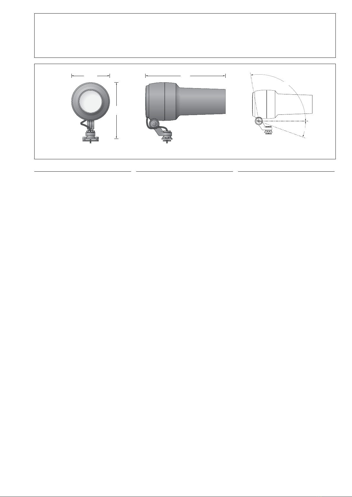
Lichttechnik
Ausstrahlwinkel 10°-14° Lighting technology
Beam angle 10°-14° Technique d’éclairage
Angles de rayonnement 10°-14°

BEGA Gantenbrink-Leuchten KG · Postfach 31 60 · 58689 Menden · info@bega.com · www.bega.com 5/5
Reinigung · Pege
Leuchte regelmäßig mit lösungsmittelfreien
Reinigungsmitteln von Schmutz und
Ablagerungen säubern.
Dafür keinen Hochdruckreiniger verwenden.
Cleaning · Maintenance
Clean luminaire regularly with solvent-free
cleansers from dirt and deposits.
Do not use high pressure cleaners.
Nettoyage · Entretien
Nettoyer régulièrement le luminaire des
dépôts et des souillures avec des produits de
nettoyage ne contenant pas de solvants.
Ne pas utiliser de nettoyeur haute pression.
Austausch des LED-Moduls
Die Bezeichnung des LED-Moduls ist auf einem
Etikett in der Leuchte vermerkt.
BEGA Ersatzmodule entsprechen in Lichtfarbe
und Lichtleistung den ursprünglich verbauten
Modulen.
Der Austausch kann mit handelsüblichem
Werkzeug durch qualizierte Personen erfolgen.
Anlage spannungsfrei schalten.
Verriegelungsstift (Innensechskant SW2,5) auf
der Rückseite im Scheinwerfergehäuse lösen.
Objektivabdeckung linksherum drehen und
abheben.
Die 4Befestigungsschrauben der
Objektiveinheit (TorxantriebT20) lösen und die
komplette Objektiveinheit abnehmen.
LED-Modul austauschen.
Bitte beachten Sie die Montageanleitung des
LED-Moduls.
Objektiveinheit aufsetzen und befestigen.
Scheinwerfer einschalten, Gobo Motivgröße
und -schärfe überprüfen und ggf. nachjustieren.
Objektivabdeckung so auf das
Scheinwerfergehäuse aufsetzen, dass
die Kerben im Scheinwerfergehäuse und
Objektivabdeckung übereinander liegen.
Objektivabdeckung rechtsherum bis zum
Anschlag aufdrehen.
Verriegelungsstift einschrauben.
Replacing the LED module
The designation of the LED module is noted on
a label in the luminaire.
The light colour and light output of BEGA
replacement modules correspond to those of
the modules originally tted.
The module can be replaced by qualied
persons using standard tools.
Disconnect the system.
Loosen the locking pin (hexagon socket wrench
SW 2.5) on the back of the oodlight housing.
Turn the lens cover clockwise and lift it off.
Undo the 4 mounting screws of the lens unit
(Torx drive T20) and remove the complete lens
unit.
Replace LED module.
Please follow the installation instructions for the
LED module.
Replace and secure the lens unit.
Switch on the oodlight, check the Gobo motif
size and focus, and adjust as needed.
Position the lens cover on the oodlight
housing so that the notches in the oodlight
housing and the lens cover are congruent.
Srew on the lens cover clockwise until the stop.
Screw in the locking pin.
Remplacement du module LED
La désignation du module LED est inscrite sur
une étiquette collée dans le luminaire.
Les modules de rechange BEGA
correspondent aux modules d’origine en
termes de couleur de lumière et de ux
lumineux. Le module LED peut être remplacé
par une personne qualiée à l’aide d’outils
disponibles dans le commerce.
Travailler hors tension.
Desserrer la goupille de verrouillage (six pans
creux SW2,5) au dos du boîtier du projecteur.
Tourner le cache de l’objectif vers la gauche et
le soulever.
Dévisser les 4vis de xation de l’unité de
l’objectif (couple de serrage Torx T20) et retirer
l’unité complète.
Remplacer le module LED.
Respecter la notice de montage du module
LED.
Positionner l’unité de l’objectif et la xer.
Allumer le projecteur, vérier la taille et la
résolution du motif Gobo et au besoin,
procéder aux ajustements.
Placer le cache de l’objectif sur le boîtier du
projecteur de manière à ce que les encoches
du boîtier du projecteur et du cache de
l’objectif se superposent.
Fixer le cache de l’objectif en tournant vers la
droite jusqu’à la butée.
Visser la goupille de verrouillage.
Ergänzungsteile
Für diese Leuchte empfehlen wir folgende
BEGA Lichtmaste:
Prolmaste aus Aluminium, lackiert
84 700 quadratisch H 4000 mm
84 701 quadratisch H 6000 mm
84 702 rund H 4000 mm
84 703 rund H 6000 mm
Prolmaste mit Leimholz nach DINEN14 080
84 696 quadratisch H 4000 mm
84 697 quadratisch H 6000 mm
84 698 rund H 4000 mm
84 703 rund H 6000 mm
Accessories
For this luminaire we recommend the
followingBEGA luminaire poles:
Prole poles made of lacquered aluminium
84 700 square H 4000mm
84 701 square H 6000mm
84 702 round H 4000mm
84 703 round H 6000mm
Prole poles with glued laminated wood in
accordance with DINEN14 080
84 696 square H 4000mm
84 697 square H 6000mm
84 698 round H 4000mm
84 703 round H 6000mm
Accessoires
Pour ce luminaire nous recommandons les
mâts BEGA suivants :
Mâts prolés en aluminium laqué
84 700 carré H 4000mm
84 701 carré H 6000mm
84 702 rond H 4000mm
84 703 rond H 6000mm
Mâts prolés avec bois lamellé-collé selon
DINEN14 080
84 696 carré H 4000mm
84 697 carré H 6000mm
84 698 rond H 4000mm
84 703 rond H 6000mm
Zu den Ergänzungsteilen gibt es eine
gesonderte Gebrauchsanweisung. For the accessories a separate instructions
for use can be provided upon request. Une che d’utilisation pour ces accessoires est
disponible.
Ersatzteile
Blende ø 20 mm 16 006 501
Blende ø 30 mm 16 006 502
Objektivabdeckung grat 25 000 165
Objektivabdeckung silber 25 000 166
LED-Netzteil DEV-0418/225i
LED-Modul LED-1265/RGBW
Dichtung Gehäuse 83 000 521
Dichtung Objektivabdeckung 83 001 952
Spares
Shield ø 20 mm 16 006 501
Shield ø 30 mm 16 006 502
Lens cover graphite 25 000 165
Lens cover silver 25 000 166
LED power supply unit DEV-0418/225i
LED module LED-1265/RGBW
Gasket housing 83 000 521
Gasket Lens cover 83 001 952
Pièces de rechange
Visière ø 20 mm 16 006 501
Visière ø 30 mm 16 006 502
Cache de l’objectif graphite 25 000 165
Cache de l’objectif argent 25 000 166
Bloc d’alimentation LED DEV-0418/225i
Module LED LED-1265/RGBW
Joint du boîtier 83 000 521
Joint Cache de l’objectif 83001 952
Table of contents
Other BEGA Outdoor Light manuals
Popular Outdoor Light manuals by other brands

Thorn
Thorn ADELIE Series installation instructions

Access Lighting
Access Lighting Nostalgia 23766 installation instructions

Catellani & Smith
Catellani & Smith Lederam Manta CWS1 Assembly instructions

Philips
Philips Ecomoods 16910/93/16 Specification sheet

HOMCOM
HOMCOM B31-460V90 manual

PLG
PLG MINI SPILLO user manual

Intermatic
Intermatic AL375 Assembly procedures

LIGMAN
LIGMAN LIGHT LINEAR PT-X 14 installation manual

Claessens' Kids
Claessens' Kids Kid’Sleep Aquarium quick start guide

Rebelle
Rebelle CYL-003 7600T LED Series installation instructions

LIGMAN
LIGMAN LADOR 13 installation manual

BEKA Schreder
BEKA Schreder OMNIstar Series manual