manuals.online logo
Brands
  1. Home
  2. •
  3. Brands
  4. •
  5. BEGA
  6. •
  7. Outdoor Light
  8. •
  9. BEGA 84 991 Series User manual

BEGA 84 991 Series User manual

BEGA Gantenbrink-Leuchten KG · Postfach 31 60 · 58689 Menden · info@bega.com · www.bega.com
29.18 · Technische Änderungen vorbehalten · Technical amendments reserved · Modications techniques réservées
IP 65
!
Lichtbauelement
Light building element
Prolé lumineux
84 991
4000800
600
500
1415
Ø 140
Ø 76
150 305 x 95
Gebrauchsanweisung Instructions for use Fiche d’utilisation
Anwendung
Lichtbauelement mit rotationssymmetrischer
Lichtstärkeverteilung für die Beleuchtung und
die Gestaltung von Plätzen, Zufahrten und
Eingangsbereichen.
Lichtbauelemente sind Leuchten, die
Außenräume gliedern und strukturieren können.
Sie haben eine orientierende, leitende und
begrenzende Funktion.
Application
Light building element with rotationally
symmetrical light distribution for lighting and
designing squares, access roads and entrance
areas.
Light building elements are luminaires which
can devide and structure areas in exterior
application. They have a orientating, directing
and demarcating function.
Utilisation
Prolé lumineux à répartition lumineuse
à rotation symétrique, pour l’éclairage et
l’aménagement de places, de voies d'accès
et d'entrées. Les prolés lumineux sont des
luminaires permettant de dénir et de structurer
les espaces extérieurs.
Ils ont une fonction d'orientation, de balisage et
de délimitation.
Leuchtmittel
Modul-Anschlussleistung 46,8W
Leuchten-Anschlussleistung 54W
Bemessungstemperatur ta=25 °C
Umgebungstemperatur ta max = 35 °C
84 991 K4
Modul-Bezeichnung 12x LED-0701/840
Farbtemperatur 4000K
Farbwiedergabeindex CRI > 80
Modul-Lichtstrom 8940lm
Leuchten-Lichtstrom 7354lm
Leuchten-Lichtausbeute 136,2 lm / W
84 991 K3
Modul-Bezeichnung 12x LED-0701/830
Farbtemperatur 3000K
Farbwiedergabeindex CRI > 80
Modul-Lichtstrom 8700lm
Leuchten-Lichtstrom 7156lm
Leuchten-Lichtausbeute 132,5 lm / W
Lamp
Module connected wattage 46.8W
Luminaire connected wattage 54W
Rated temperature ta=25 °C
Ambient temperature ta max = 35 °C
84 991 K4
Module designation 12x LED-0701/840
Colour temperature 4000K
Colour rendering index CRI > 80
Module luminous ux 8940lm
Luminaire luminous ux 7354lm
Luminaire luminous efciency 136,2 lm / W
84 991 K3
Module designation 12x LED-0701/830
Colour temperature 3000K
Colour rendering index CRI > 80
Module luminous ux 8700lm
Luminaire luminous ux 7156lm
Luminaire luminous efciency 132,5 lm / W
Lampe
Puissance raccordée du module 46,8W
Puissance raccordée du luminaire 54W
Température de référence ta=25 °C
Température d’ambiance ta max = 35 °C
84 991 K4
Marquage des modules 12x LED-0701/840
Température de couleur 4000K
Indice de rendu des couleurs CRI > 80
Flux lumineux du module 8940lm
Flux lumineux du luminaire 7354lm
Rendement lum. d’un luminaire 136,2 lm / W
84 991 K3
Marquage des modules 12x LED-0701/830
Température de couleur 3000K
Indice de rendu des couleurs CRI > 80
Flux lumineux du module 8700lm
Flux lumineux du luminaire 7156lm
Rendement lum. d’un luminaire 132,5 lm / W
BEGA Gantenbrink-Leuchten KG · Postfach 31 60 · 58689 Menden · info@bega.com · www.bega.com
Sicherheit
Für die Installation und für den Betrieb
dieser Leuchte sind die nationalen
Sicherheitsvorschriften zu beachten.
Der Hersteller übernimmt keine Haftung für
Schäden, die durch unsachgemäßen Einsatz
oder Montage entstehen.
Werden nachträglich Änderungen an der
Leuchte vorgenommen, so gilt derjenige als
Hersteller, der diese Änderungen vornimmt.
Safety indices
The installation and operation of this luminaire
are subject to national safety regulations.
The manufacturer is then discharged from
liability when damage is caused by improper
use or installation.
If any luminaire is subsequently modied, the
persons responsible for the modication shall
be considered as manufacturer.
Sécurité
Pour l’installation et l’utilisation de ce luminaire,
respecter les normes de sécurité nationales.
Le fabricant décline toute responsabilité
résultant d'une mise en œuvre ou d'une
installation inappropriée du produit.
Toutes les modications apportées au luminaire
se feront sous la responsabilité exclusive de
celui qui les effectuera.
Überspannungsschutz
Die in der Leuchte verbauten elektronischen
Komponenten sind nach DINEN61547 gegen
Überspannung geschützt.
Um einen zusätzlichen Schutz z.B. vor
Transienten etc. zu erreichen, empfehlen wir
separate Überspannungsschutzkomponenten.
Sie nden diese auf unserer Website unter
www.bega.de.
Overvoltage protection
The electronic components installed in the
luminaire are protected against overvoltage in
accordance with DINEN61547.
To achieve an additional protection against
e.g. transients, etc. we recommend separate
overvoltage protection components.
You can nd them on our website at
www.bega.com.
Protection contre les surtensions
Les composants électroniques installés dans
le luminaire sont protégés contre la surtension
conformément à la norme DINEN61547.
Pour obtenir une protection supplémentaire
contre la surtension, les tensions transitoires
etc., nous proposons des composants de
protection séparés. Vous les trouverez sur notre
site web www.bega.com.
Produktbeschreibung
Leuchte besteht aus Aluminiumguss,
Aluminium und Edelstahl
Kunststoffzylinder weiß
Mast aus Aluminium und Aluminiumguss
Erdstücklänge 800 mm
2 gegenüberliegende Kabeleinführungen
150 x 50 mm
Anschraubbare Grundplatte ca. 250 x 250 mm
3 m Verbindungsleitung X05BQ-F 5 G 1@
Mit eingesetzter Tür aus Aluminiumdruckguss
Türverschluss – Vierkant –
Schlüsselweite 8 mm
C-Schiene mit Potentialklemme bis 16@
und 2 Schiebemuttern M6 mit eingebautem
Anschlusskasten 70 632
zur Durchverdrahtung – für 2 Kabel bis 5 x 4@
mit Schmelzsicherung Neozed D 01 · 6 A
LED-Netzteil
220-240V x 0/50-60Hz
DC 170-280V
Dimmbar 1-10 V
Nur mit SELV (Schutzkleinspannung)
Zwischen Netz- und Steuerleitungen ist eine
Basisisolierung vorhanden
Leuchte: Schutzart IP 65
Staubdicht und Schutz gegen Strahlwasser
Schutzklasse I
Schlagfestigkeit IK08
Schutz gegen mechanische
Schläge < 5 Joule
c – Konformitätszeichen
Windangriffsäche:0,6m²
Gewicht: 26,0 kg
Product description
Luminaire made of aluminium alloy,
aluminium and stainless steel
Plastic cylinder, white
Luminaire pole made of aluminium
and aluminium alloy
Length of anchorage section 800 mm
2 opposite cable entries 150 x 50 mm
Screw-on ground plate approx. 250 x 250 mm
3 m Connecting cable X05BQ-F 5 G 1@
With inserted door made of die cast aluminium
Door latch – square spanner –
wrench size 8mm.
C-clamp with earth clamp 16@
and 2 sliding nuts M6
with built-in connection box 70 632
for through-wiring – for 2 cables up to 5x4@
with fuse Neozed D 01 · 6 A
LED power supply unit
220-240V x 0/50-60Hz
DC 170-280V
Dimmable 1-10 V
SELV (safety extra-low voltage)
A basic isolation exists between power cable
and control line
Luminaire: Protection class IP 65
Dust-tight and protection against water jets
Safety class I
Impact strength IK08
Protection against mechanical
impacts < 5 joule
c – Conformity mark
Wind catching area:0.6m²
Weight: 26.0 kg
Description du produit
Luminaire fabriqué en fonderie d'alu,
aluminium et acier inoxydable
Cylindre synthétique blanc
Mât fabriqué en aluminium et en fonte
d'aluminium - Partie à enterrer 800 mm
2 entrées de câble opposées 150 x 50 mm
Plaque de stabilisation à visser d'environ
250 x 250 mm
3 m câble de raccordement X05BQ-F 5 G 1@
Avec porte fabriquée en fonderie d'alu
Fermeture - goujon carré -
Ouverture de clef 8 mm
Rail de montage avec raccordement de mise
à la terre 16@ et 2 écrous coulissants M6 avec
boîte de connexion 70 632
pour branchement en dérivation
pour 2 câbles max. 5 x 4@
et avec fusible Neozed D 01 · 6 A
Bloc d'alimentation LED
220-240V x 0/50-60Hz
DC 170-280V
Gradable 1-10 V
Uniquement avec SELV (très basse
tension)
Une isolation existe d’origine entre le secteur et
les câbles de commande
Luminaire: Degré de protection IP 65
Etanche à la poussière et protégé contre les
jets d’eau
Classe de protection I
Résistance aux chocs mécaniques IK08
Protection contre les chocs
mécaniques < 5 joules
c – Sigle de conformité
Prise au vent:0,6m²
Poids: 26,0 kg
400 × 400
700
800
befestigte Oberfläche
Paved surface
Surface consolidée
verdichteter Boden
Compacted soil
Sol damé
Erdreich · Soil · Terre
Sauberkeitsschicht
Sub-base
Couche d’assainissement
Drainage · Drainage · Drainage
Beton · Concrete · Béton
BEGA Gantenbrink-Leuchten KG · Postfach 31 60 · 58689 Menden · info@bega.com · www.bega.com
Mastmontage
Für den elektrischen Anschluss der Leuchte ist
eine Kabellänge von ca. 1m über Oberkante
Bodenbelag ausreichend. Die Schutzschicht im
Bereich des Erdstückes darf nicht beschädigt
werden.
Zweiteilige Grundplatte aus dem Mastrohr
entnehmen und am Mast befestigen. Die
Fundamentgröße ist abhängig von der
Topographie, Bodenbeschaffenheit und
Windbelastung und muss jeweils bauseits
bestimmt werden. Dazu gelten die Normen
DIN EN 50 341 und DIN 1045.
Die obige beispielhafte Fundamentempfehlung
gilt nur für einen tragfähigen Baugrund und
nur für das Lichtbauelement 84 991. Tür
mit beiliegendem Vierkantschlüssel öffnen
und entnehmen. Erdkabel durch seitliche
Kabeleinführung in den Mast führen. Leuchte
standsicher gründen.
Pole installation
For the electrical connection a cable length
of approx. 1m above mounting surface
is sufcient. The protective coating at the
anchorage unit must not be damaged.
Remove the two-part ground plate from the
pole tube and x it at the pole. The size of
the foundation depends on the topography,
condition of the soil and the wind load and
must be determined on site. The norms
DIN EN 50 341 and DIN 1045 apply.
The above exemplary recommendation for
a foundation is only applicable for a stable
subgrade and for the light building element
84 991 only. Open door with enclosed square
spanner and remove door. Lead underground
cable into the pole through the lateral cable
entry. Set luminaire in a stable foundation.
Installation du mât
Pour le raccordement électrique du luminaire
une longueur de câble d'environ 1m au-dessus
du bord supérieur de la couche de nition du
sol est sufsante. La couche protectrice de la
pièce à enterrer ne doit pas être endommagée.
Retirer du mât la plaque de stabilisation se
composant de deux pièces. La xer au mât
à l'aide des vis fournies. Le volume et les
dimensions du massif béton dépendent de
la topographie, la pression à fond de fouille
du sol, de la zone de vent, ainsi que des
forces et des charges exercées et doivent
être individuellement dénis sur le chantier. Se
rapporter pour cela exclusivement aux normes
DIN EN 50341 et DIN 1045.
Le massif de fondation recommandé ci-dessus
est un exemple uniquement valable pour un
terrain à bâtir solide et uniquement pour le
luminaire 84 991. Déverrouiller et retirer la porte
avec la clé jointe. Introduire le câble réseau
dans le mât par l'entrée de câble latérale. Fixer
le luminaire fermement dans la fondation.
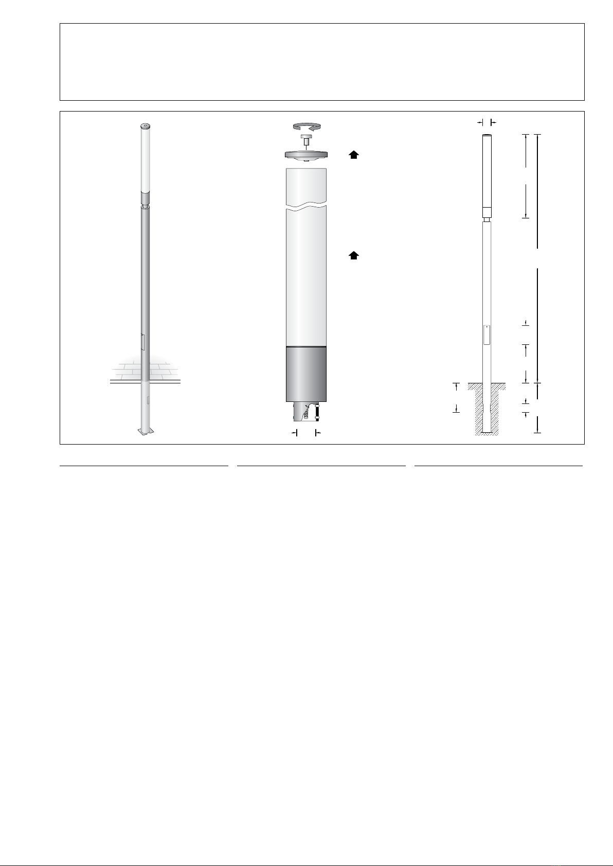
Leuchtenmontage:
Bitte beachten Sie:
Für den Austausch des LED-Moduls und
Wechsel der Kunststoffabdeckung ist oberhalb
der Leuchte ein freier Raum von 1300mm
erforderlich.
Verbindungsleitung in Mast einführen und
Leuchtenmuffe auf Mastzopf befestigen.
Anzugsdrehmoment = 12 Nm.
Anschlusskasten öffnen.
Erdkabel in den Anschlusskasten führen.
Schutzleiterverbindung herstellen und
elektrischen Anschluss vornehmen.
Leuchtenanschlussleitung im Anschlusskasten
anschließen.
Auf richtige Belegung der Anschluss-
leitung achten. Den Netzanschluss an der
braunen (L), blauen (N) und grün-gelben Ader
(1) vornehmen. Die Dimmung erfolgt über die
beiden mit 1-10 V + und 1-10 V -
gekennzeichneten Adern.
Achtung:
Die Dimmung 1-10 V darf nur mit einer
1-10 V SELV (Schutzkleinspannung)
Versorgungseinheit betrieben werden.
Bei Nichtbelegung dieser Adern wird die
Leuchte mit voller Lichtleistung betrieben.
Anschlusskasten schließen.
Tür einsetzen und verriegeln.
Installation of the luminaire:
Please note:
1300mm space above the luminaire is required
for replacement the LED module and to change
the synthetic diffuser.
Lead the connecting cable into the pole.
Place luminaire on top of the pole.
Fix the luminaire with screws.
Torque = 12 Nm.
Open the connection box.
Lead the mains supply cable into the
connection box. Make earth conductor
connection and electrical connection.
Connect luminaire connection cable in the
connection box.
Note correct conguration of the mains supply
cable.
The phase is connected to the brown wire (L),
the neutral conductor to the blue wire (N) and
earth conductor at the (1) marked wire.
Dimming is achieved by means of the both
leads marked with 1-10 V + and 1-10 V - .
Please note:
Dimming 1-10 V must only be operated
with a 1-10 V SELV (safety extra low
voltage) supply unit.
In case these leads are not used the luminaire
will be operated at full light output.
Close the connection box.
Install the door and lock it.
Installation du luminaire:
Attention:
Pour le changement de l'élément LED et de
la vasque synthétique prévoir un espace de
1300mm au-dessus du luminaire.
Introduire le câble d’alimentation dans
l’ouverture au sommet du mât et xer le
luminaire sur le mât.
Moment de serrage = 12 Nm.
Ouvrir la boîte de connexion.
Introduire le câble réseau dans la boîte de
connexion à travers l'entrée de câble. Mettre à
la terre et procéder au raccordement électrique.
Raccorder le câble d’alimentation dans la boîte
de connexion.
Veiller au bon adressage du câble de
raccordement. La phase doit être raccordée au
l brun (L) et le conducteur neutre au l bleu (N)
et le conducteur protective au l marqué (1).
La gradation est effectuée avec les deux ls
marqués 1-10 V + et 1-10 V -
Attention:
La gradation 1-10 V ne doit être effectuée
qu'avec un bloc d'alimentation très basse
tension de sécurité 1-10 V.
Si ces ls ne sont pas raccordés le luminaire
fonctionne sur la puissance maximale.
Fermer la boîte de connexion.
Installer et fermer la porte.
Austausch des LED-Moduls
Die Bezeichnung des LED-Moduls ist auf einem
Etikett in der Leuchte vermerkt.
BEGA Ersatzmodule entsprechen in
Lichtfarbe und Lichtleistung den ursprünglich
verbauten Modulen. Der Austausch kann mit
handelsüblichem Werkzeug durch qualizierte
Personen erfolgen.
Anlage spannungsfrei schalten.
Zum Reinigen der Leuchte nur
lösungsmittelfreie Reinigungsmittel und keine
Hochdruckreiniger verwenden.
Zum Öffnen der Leuchte
Innensechskantschraube (SW 10) im
Leuchtenoberteil lösen und Leuchtenoberteil
abnehmen.
Kunststoffzylinder senkrecht abheben.
Bitte beachten Sie die Montageanleitung des
LED-Moduls.
Dichtungen überprüfen, ggf. ersetzen.
Kunststoffzylinder über die Lampen führen,
Dach mit Dichtungsteller aufschrauben und
mit zentraler Verschraubung bis auf Anschlag
verschrauben.
Anzugsdrehmoment = 16 Nm.
Dabei auf richtigen Sitz der Dichtung achten.
Replacing the LED module
The designation of the LED module is noted on
a label in the luminaire.
The light colour and light output of BEGA
replacement modules correspond to those
of the modules originally tted. The module
can be replaced by qualied persons using
standard tools.
Disconnect the electrical installation.
Use only solvent-free cleansers for cleaning the
luminaire.
For cleaning do not use a high pressure
cleaner.
To open the luminaire undo the hexagon socket
head screw (wrench size 10) in the covering
cap and remove covering cap.
Lift plastic cylinder vertically.
Please follow the installation instructions for the
LED module.
Check gaskets and replace if necessary.
Slide plastic cylinder over the lamps, screw
on luminaire roof with gasket plate and bolt it
together with central screw connection as far
as it will go.
Torque = 16 Nm.
Make sure that gasket is positioned correctly.
Remplacement du module LED
La désignation du module LED est inscrite sur
une étiquette apposée sur le luminaire.
Les modules de rechange BEGA
correspondent aux modules d’origine en
termes de couleur de lumière et de ux
lumineux. Le module LED peut être remplacé
par une personne qualiée à l’aide d’outils
disponibles dans le commerce.
Travailler hors tension.
Pour le nettoyage du luminaire n'utilliser
que des produits de nettoyage ne contenant
pas de solvant et ne pas utiliser de
nettoyeur haute pression.
Pour ouvrir le luminaire desserrer les vis à six
pans creux (SW 10) et retirer le couvercle de
fermeture.
Soulever verticalement le cylindre synthétique.
Respecter la che d’utilisation du module LED.
Vérier les joints, le cas échéant les remplacer.
Installer le cylindre synthétique sur les lampes
et visser le couvercle en contentant le disque
du joint et visser avec la fermeture centrale
jusqu'à la butée.
Moment de serrage = 16 Nm.
Veiller au bon emplacement du joint.
BEGA Gantenbrink-Leuchten KG · Postfach 31 60 · 58689 Menden · info@bega.com · www.bega.com
Ersatzteile
Kunststoffzylinder 15000329
LED-Netzteil DEV-0153/700
LED-Modul 3000 K LED-0701/830
LED-Modul 4000 K LED-0701/840
Dichtung Unterteil 83000678
Dichtung Dachverschraubung 83000981
Dichtung Leuchtenoberteil 83001073
Spares
Synthetic cylinder 15000329
LED power supply unit DEV-0153/700
LED module 3000 K LED-0701/830
LED module 4000 K LED-0701/840
Gasket lower part 83000678
Gasket screw connection roof 83000981
Gasket covering cap 83001073
Pièces de rechange
Cylindre synthétique 15000329
Bloc d’alimentation LED DEV-0153/700
Module LED 3000 K LED-0701/830
Module LED 4000 K LED-0701/840
Joint de la partie inférieure 83000678
Joint de fermeture de couvercle 83000981
Joint de la partie supérieure 83001073

This manual suits for next models

2

Other BEGA Outdoor Light manuals

BEGA 33 296 Manual

BEGA

BEGA 33 296 Manual

BEGA 33 386 User manual

BEGA

BEGA 33 386 User manual

BEGA 22 203 Manual

BEGA

BEGA 22 203 Manual

BEGA 84 061 Manual

BEGA

BEGA 84 061 Manual

BEGA 84 128 Manual

BEGA

BEGA 84 128 Manual

BEGA 99 558 Manual

BEGA

BEGA 99 558 Manual

BEGA 24 011 Manual

BEGA

BEGA 24 011 Manual

BEGA 99 282 User manual

BEGA

BEGA 99 282 User manual

BEGA 84 991 User manual

BEGA

BEGA 84 991 User manual

BEGA 33 242 User manual

BEGA

BEGA 33 242 User manual

BEGA 88 977 User manual

BEGA

BEGA 88 977 User manual

BEGA 22 052 Manual

BEGA

BEGA 22 052 Manual

BEGA 84 020 User manual

BEGA

BEGA 84 020 User manual

BEGA 77 247 User manual

BEGA

BEGA 77 247 User manual

BEGA 99 635 User manual

BEGA

BEGA 99 635 User manual

BEGA 33 592 User manual

BEGA

BEGA 33 592 User manual

BEGA 84 314 User manual

BEGA

BEGA 84 314 User manual

BEGA 77 011 User manual

BEGA

BEGA 77 011 User manual

BEGA 88 066 Manual

BEGA

BEGA 88 066 Manual

BEGA 70 238 User manual

BEGA

BEGA 70 238 User manual

BEGA UniLink 84 824 User manual

BEGA

BEGA UniLink 84 824 User manual

BEGA 84 761 User manual

BEGA

BEGA 84 761 User manual

BEGA Strasbourg 31 552 User manual

BEGA

BEGA Strasbourg 31 552 User manual

BEGA 84 320 User manual

BEGA

BEGA 84 320 User manual

Popular Outdoor Light manuals by other brands

emaux E-Fusion operating manual

emaux

emaux E-Fusion operating manual

LUXIONA STREETPARK LED manual

LUXIONA

LUXIONA STREETPARK LED manual

LIGMAN LI-10032 installation manual

LIGMAN

LIGMAN LI-10032 installation manual

bover FORA APLIQUE Assembly instructions

bover

bover FORA APLIQUE Assembly instructions

EcoEnergy EE-20-DL01 user manual

EcoEnergy

EcoEnergy EE-20-DL01 user manual

Kichler Lighting 16099BK manual

Kichler Lighting

Kichler Lighting 16099BK manual

GEV FRIEDA 2432 manual

GEV

GEV FRIEDA 2432 manual

Iluminarc Ilumiline SL user manual

Iluminarc

Iluminarc Ilumiline SL user manual

LIGMAN SA-31553 installation manual

LIGMAN

LIGMAN SA-31553 installation manual

oluce COUPÉ 3320 R Mounting instructions

oluce

oluce COUPÉ 3320 R Mounting instructions

Unilamp QUARK Square - Asymmetric installation manual

Unilamp

Unilamp QUARK Square - Asymmetric installation manual

VERTUO 44001015 Assembly guide

VERTUO

VERTUO 44001015 Assembly guide

Maretti Stone base PENTHOUSE 18 quick start guide

Maretti

Maretti Stone base PENTHOUSE 18 quick start guide

Platek GRANDE Assembly instructions

Platek

Platek GRANDE Assembly instructions

Pro-Elec PEL00824 quick guide

Pro-Elec

Pro-Elec PEL00824 quick guide

RS 600-723 Instruction leaflet

RS

RS 600-723 Instruction leaflet

Living & Co JUNO WHITE instructions

Living & Co

Living & Co JUNO WHITE instructions

eLEDing EE800W-SHRC Series Installation instruction

eLEDing

eLEDing EE800W-SHRC Series Installation instruction

manuals.online logo
manuals.online logoBrands
  • About & Mission
  • Contact us
  • Privacy Policy
  • Terms and Conditions

Copyright 2025 Manuals.Online. All Rights Reserved.