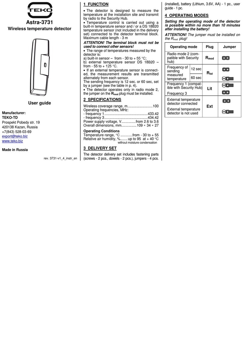
manuals.online logo
Brands
  1. Home
  2. •
  3. Brands
  4. •
  5. teko
  6. •
  7. Security Sensor
  8. •
  9. teko Astra-517 User manual

teko Astra-517 User manual

Редакция 517-v1_0
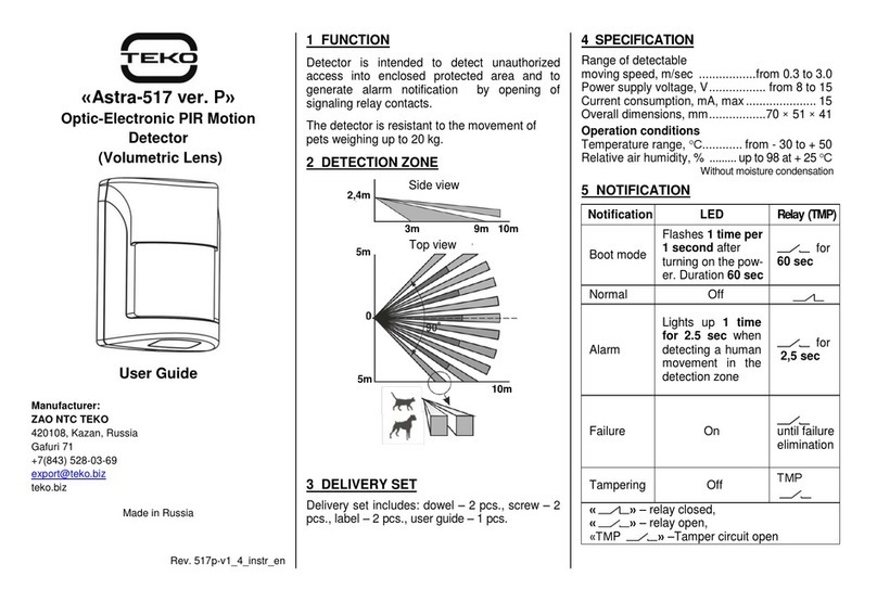
Astra-517 (Volumetric Lens)
Optic-Electronic PIR Motion Detector
Operating Manual
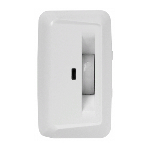
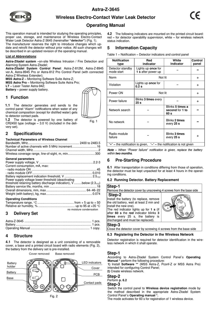
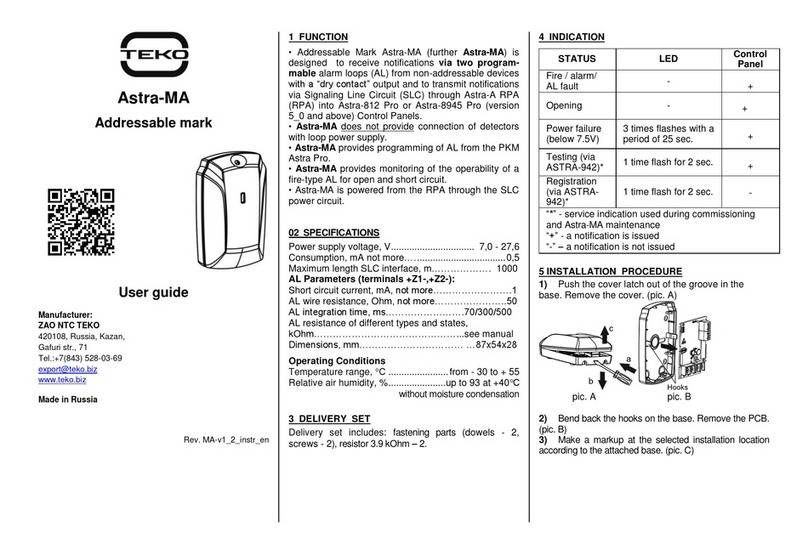
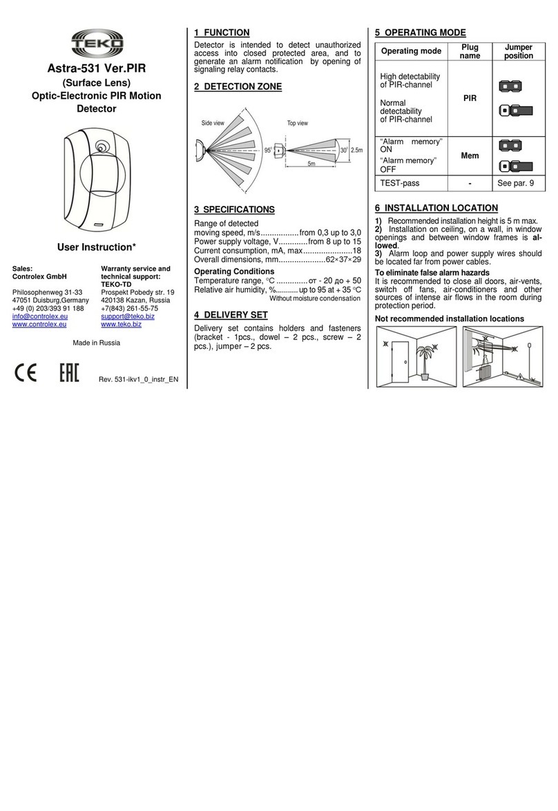
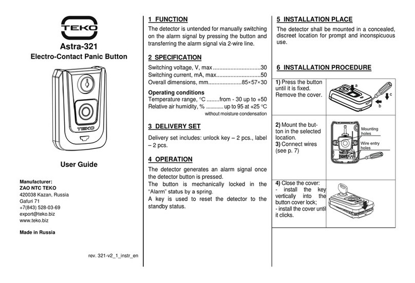
The present Operating Manual is intended to provide a guid-
ance on operating principles, correct use, storage and mainte-
nance for the PIR detector “Astra-517” (hereinafter-detector)
(Figure1).
The manufacturer reserves the right to make improvements in
the design of the detector without prior notice. The alternations
shall be included into a new edition of the Operating Manual.
1 Application
1.1 The detector is purposed to detect in-
trusion into a protected area indoors and to
generate an alarm notification by opening
of the signal relay output contacts.
1.2 The detector is powered from any DC
power supply with nominal voltage of
12V and maximum pulsation amplitude
0,1V.
2 Principle of Operation
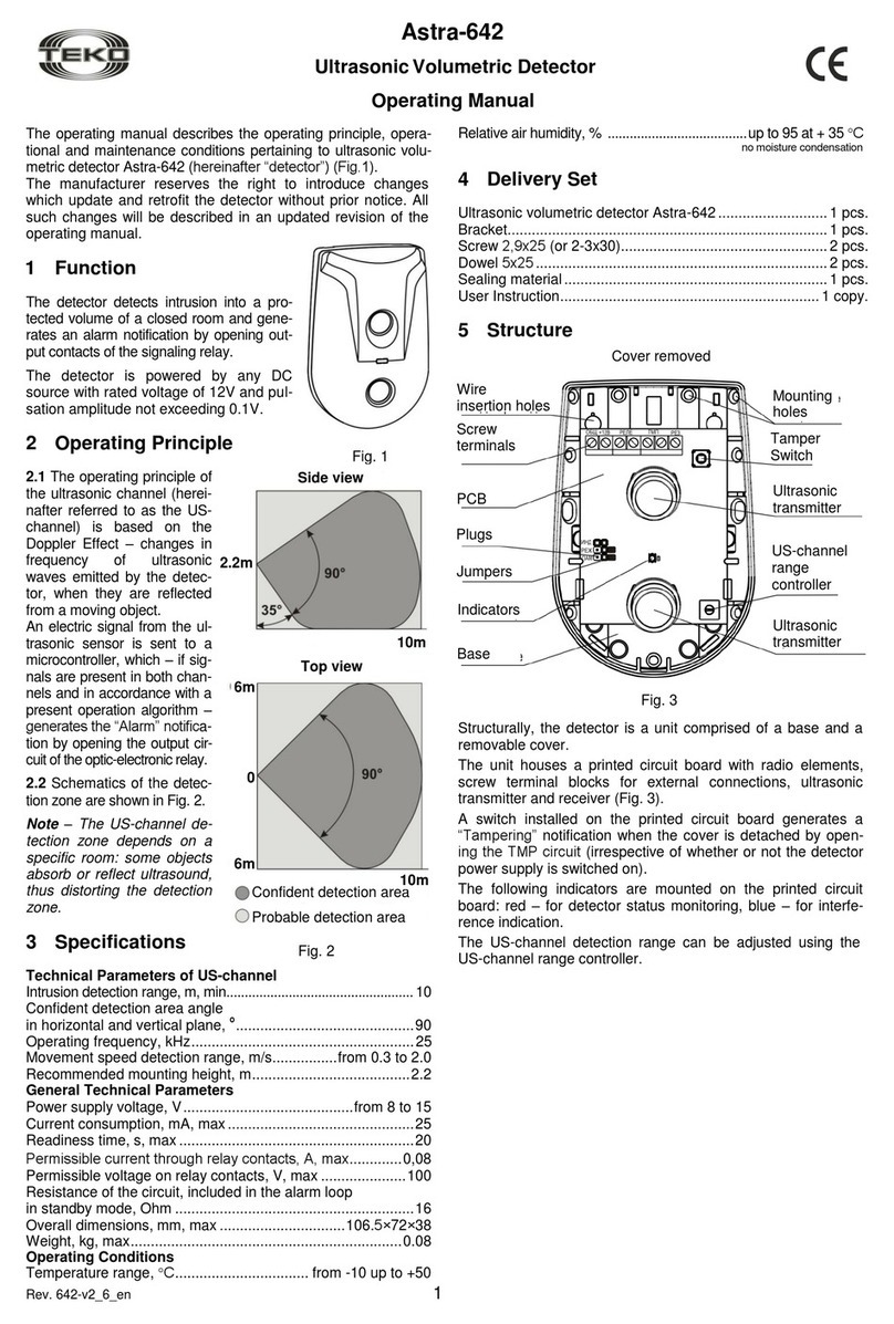
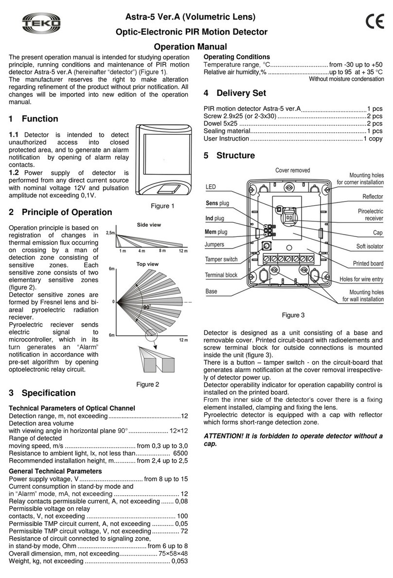
2.1 The operating principle
is based on registration of
changes occurring in ther-
mal flux, when a person
crosses a detection zone,
consisting of sensitive
zones. Each sensitive zone
consists of two elementary
sensitive zones (Figure 2).
The sensitive zones of the
detector are formed by a
Fresnel lens and a bi-areal
pyroelectric sensor.
Electric signals from the
pyroelectric sensor shall be
sent to a microcontroller,
which generates alarm no-
tification in accordance
with a preset operation al-
gorithm by opening of op-
toelectronic relay circuit.
2.2 The sizes of detection
zone may be varied due to
the position of the printed circuit board of the detector. With in-
trusion detection range of 8 m, density of the sensitive areas
will be increased.
3 Specifications
Technical Parameters of PIR-channel
Intrusion detection range, m, min:
- lower PC board position...............................................................12
- upper PC board position................................................................ 8
Sizes of detection zone at viewing angle 90оin horizontal
plane, m:
- in lower PC board position.................................................12×12
- in upper PC board position .........................................................8×8
Detectable motion speed range, m/s ................. from 0.3 to 3.0
Resistance to ambient light, lx, min................................... 6500
Advised mounting height, m................................from 2.2 to 2.4
General technical parameters
Power supply voltage, V..........................................from 8 to 15
Current consumption in standby
mode and in Alarm mode, mA, max .......................................12
Permissible current through relay contacts, А, max.............0,08
Permissible voltage on relay contacts, V, max .....................100
Resistance of circuit connected to
alarm loop in standby mode, Ohm, max ................................. 8
Dimensions, mm, max ............................................... 70×51×41
Weight, kg max................................................................... 0,05
Operating Conditions
Temperature range, °С....................................from - 30 to + 50
Relative air humidity, %....................................up to 98 at + 25 °С
without moisture condensation
4 Delivery Set
PIR motion detector Astra-517...........................................1 pcs.
Bracket...............................................................................1 pcs.
Screw 2,9х25 (or 2-3х30)...................................................2 pcs.
Dowel 5х25 ........................................................................2 pcs.
User instruction..................................................................1 pcs.
5 Structure
Figure 3
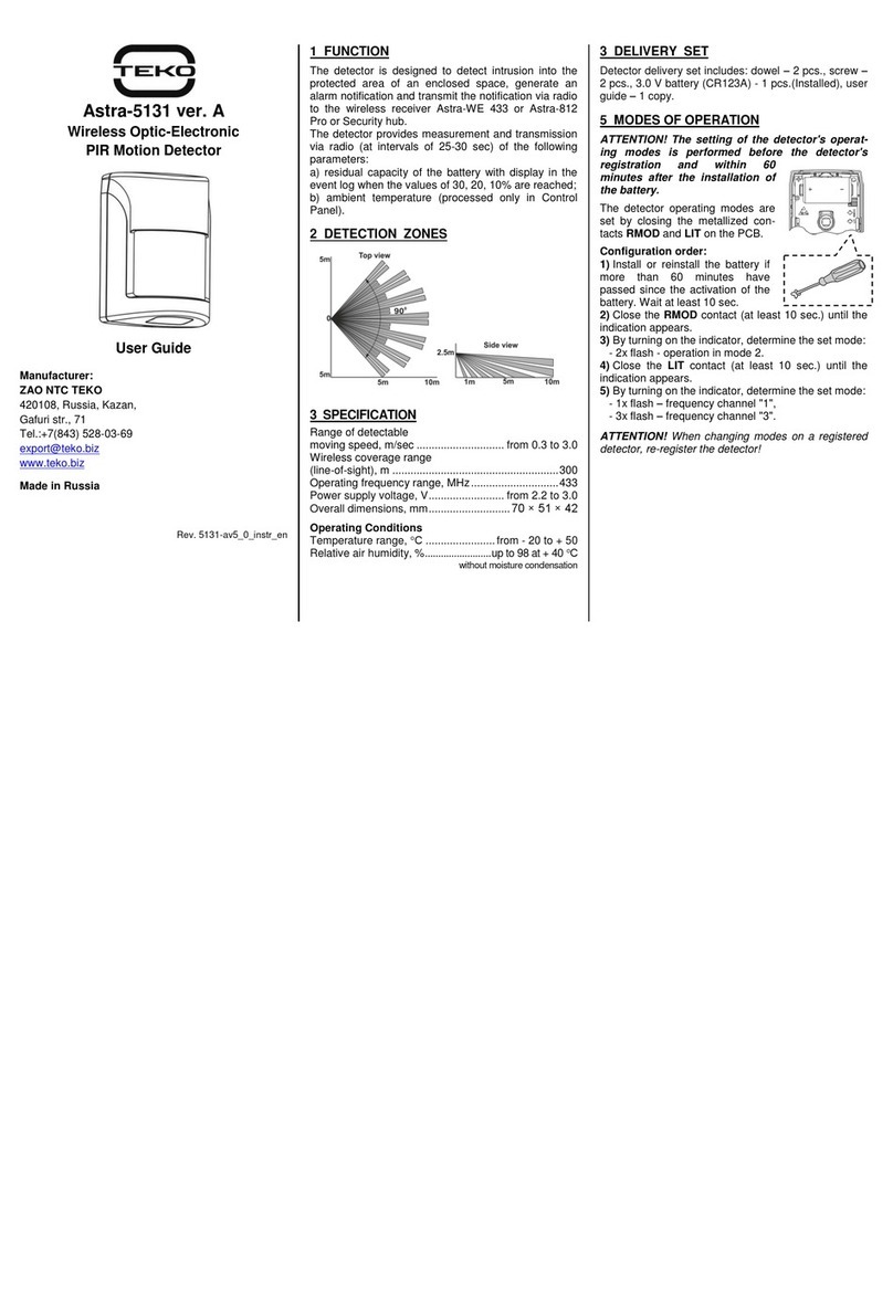
5.1 The detector is a unit consisting of a base and a detacha-
ble cover. A printed circuit board with radio elements and a
block of screw terminals for external connections is installed
inside the unit. (Figure 3).
5.2 The PC board shall be secured in the position to enable the
desired detection range (8m, 12m) of the detector with a
screw.
5.3 The PC board includes an indicator, which controls operation
of the detector.
5.4 The cover on the inside is provided with a lock pin holding
down and securing the lens.
5.5 The pyroelectric sensor is equipped with a cap provided
with a reflector making a near detection area.
WARNING! It is prohibited to operate the detector without the
cap.
5.6 The detector can be mounted either directly on the wall or
in a room corner, or it can be mounted using brackets (includ-
ed in the scope of delivery).
Figure 1
Figure 1
Редакция 517-v1_0
2
6 Information Capacity
Table 1 - Notifications to indicator and relay
Event Type
Indicator
Relay
Switching to
standby mode
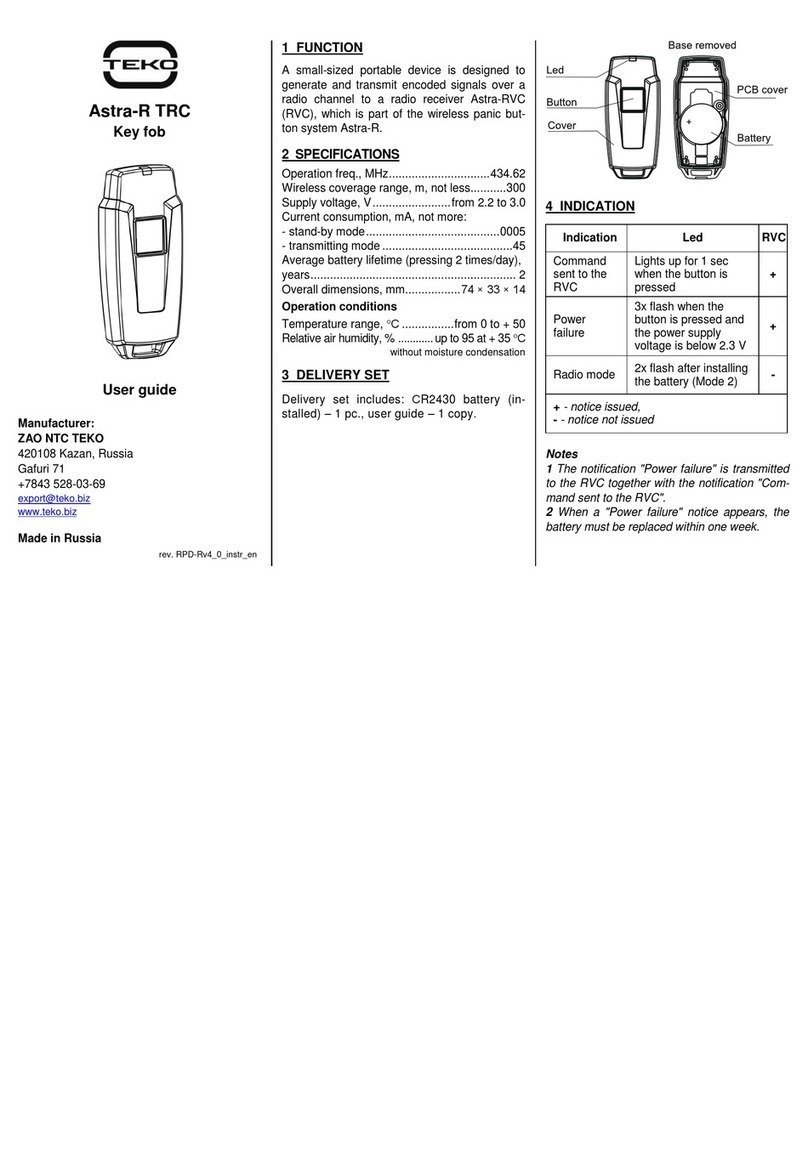
After power is on, blinks
once per second within
60s
within 60 s
Normal
Off
Alarm
Lights up 1 time for 4 s
when detects a person
moving in the detection
zone (if indication is per-
mitted)
within 4 s
Alarm in “Alarm
Memory”mode
Figure 4
within 4 s
Failure
On
Tampering
Off
ТМP
"" –relay closed,
"" –relay open,
"ТМP " –ТМP circuit open
Figure 4
7 Operating Modes
Table 2 - Operating modes and their setting
Operating mode
Plug
Jumper position
High detectability
Normal detectability
Sens
Indication ON
Indication OFF
Ind
Alarm Memory ON
Alarm Memory OFF
Mem
The Alarm Memory mode enables to establish the fact
and number of zone violations, and is reflected in correspond-
ing notifications. The mode is activated in 1 minute after jump-
er sets to Mem plug or in 1 min. after detector switches to
stand-by mode, the jumper being previously installed on Mem
plug. The “Alarm” notification is indicated in 1 min. after viola-
tion of the protected area. To switch the mode off and reset in-
dication, remove jumper from Mem plug or switch power off.
8 Installation and Pre-Starting Procedure
8.1 Works on installation, mounting, maintenance and
operation of detector should be performed only by quaified
persons.
8.2 After being transported in conditions which differ from op-
erating ones, the detector must be left unpacked in operating
environment for minimum 4 hours.
8.3 How to select mounting location
8.3.1 Recommended mounting height
8.3.2 In capital buildings, detector installation on a bearing wall
is preferable.
8.3.3 For light metal constructions you should avoid mounting
of the detector directly on the wall, and prefer mounting to the
load bearing elements of the construction.
8.3.4 Wires of signaling zones and power supply circuits should
be located far from power cables.
8.3.5 We recommend close the doors, vents, turn off fans and
air conditioners, and other possible sources of strong air flows
for the protection period.
8.3.6 We do not recommend mount the detector in the follow-
ing places
8.4 Installation Procedure
1
Push the lock on the bottom
base from the cover slot.
Remove the cover
2
Loosen the screw.
Bend the hooks on the bot-
tom. Remove PC board
3
Select option a, b or c for mounting
2.2-2.4m
Редакция 517-v1_0
3
3аWALL MOUNTING
3b
CORNER MOUNTING
3c
MOUNTING USING BRACKET
Press out blanks from brack-
et mounting slots
4a,4b
Mark mounting holes on
the wall at the desired
height using the base.
ATTENTION!
Detector base should be
positioned strictly as per
figure for Step 3
4c
Mark mounting holes on the
wall at the required height
applying the bracket to
mounting surface. Mount the
bracket on the wall.
Mounting holes
5a,5b
Insert power supply and
alarm loop wires through
the dedicated wire access
hole in the detector base.
Fix the base to the wall
or in the corner
5c
Align base projection of the
detector with the bracket slot
for the ball and drive a screw
from inside of the base into
the bracket ball. Position the
detector as required and
tighten the locking screw. If
anti-sabotage zone monitor-
ing is required, set the vertical
tilt angle to 20º.
The bracket makes it possible
to turn the detector horizontally
and vertically by 40º
6
Match nib on the base hook
with a slot on the PC board
depending on the chosen de-
tection range.
Secure the PC board with a
screw.
7
Connect wires to the detector terminals
8
Switch the detector ON. The indicator shall blink once per
second within 60 s –the detector is being switched to the
standby mode
9
Remove jumpers from plugs Mem
and Sens.
Install the jumper on plug Ind
10
Place back the cover of the
detector (until clicks)
11
Perform test-pass in the secured
area at a speed of 0.5 m/s in order
to determine detection zones.
At the moment of detection (the
indicator lights up for 4s) you
should stop, spot the place and
then return one step back and
continue moving.
Repeat the TEST-pass moving back.
The sensitive zones configured by the lens will be in the
middle between the spotted places.
12
Push the lock on the bottom
base from the cover slot.
Remove the cover.
Редакция 517-v1_0
4
13
Install jumpers on plugs depending on
the chosen operation mode onsite
14
When testing the alarm system at the initial operation period
(1-2 weeks) in case of issuing false «Alarm» notifications
depending from the peculiarities of the protected premises,
remove jumper from Sens plug
15
Place back the cover of the
detector (until clicks)
8.5 To ensure reliable operation of the alarm system we rec-
ommend to test and maintain the detector at least once a
month.
Tests should be carried out as follows:
- perform test-pass through the detection zone;
- make sure “Alarm” notification appears on the control panel
and, if indication is enabled, on the detector indicator (lights up
once for 4 s during each movement) .
Maintenance should be carried out as follows:
- make sure the detector body is not broken,
- check reliability of contact connections and security of mount-
ing,
-clean the detector.
9 Labeling
The label on the case of the detector specifies:
- the trademark of the manufacturer;
- abbreviated designation of detector;
- firmware version;
- manufacture date;
- conformance mark (if there is any certificate of conformance);
- barcode, which backups the text information.
10 EC Conformity Declarations
This product is in conformity with the provisions of:
EMC 89/336/EEC
EN 61000-6-3:2005 Electromagnetic compatibility (EMC) -
Part 6-3: Generic standards - Emission standard for residen-
tial, commercial and light-industrial environments
EN 50130-4/1995 + A1:1998 + A2:2003 + Corrig. 2003 Alarm
systems - Part 4: Electromagnetic compatibility - Product fam-
ily standard: Immunity requirements for components of fire, in-
truder and social alarm systems
EN 60950-1: 2001+A11:2004+Corrig.2004 Safety of informa-
tion technology equipment
11 Recycling
The detector does not pose any threat to life and health of
people, as well as to the environment. After the expiry of its
service life period, the detector shall be disposed of without
special precautions in respect to the environment.
12 Manufacturer Warranties
12.1 Quality Management System meets provisions of ISO
9001-2011.
12.2 The manufacturer guarantees that detector will comply to
technical requirements, provided that the consumers adhere to
specified technical conditions of transportation, recommenda-
tions on storage and use.
12.3 The storage warranty time is 5 years and 6 months from
the date of manufacturing.
12.4 The operation warranty time is 5 years from the date of
operation start-up but no longer than 5 years 6 months from
the date of manufacturing.
12.5 The manufacturer must repair or replace detector within
the warranty period.
12.6 The warranty does not become effective in the follow-
ing cases:
–failure to comply with this Operating Manual;
–mechanic damage of the detector;
–the detector is improperly repaired by anyone other than the
manufacturer.
12.7 The warranty applies to the detector only. All other
equipment of other manufacturers used with detector is sub-
ject to other manufacturer’s warranties.
The manufacturer bears no responsibility for death, injury,
damage of property or any other kinds of accidental or
premeditated damages, based on user’s statement that
device failed to implement its function.
Sales, technical support:
ТЕКО-TD, LLC
Prospekt Pobedy str. 19
420138 Kazan, Russia
Phone: +7 (843) 261-55-75
Fax: +7 (843) 261-58-08
E-mail: info@teko.biz
[email protected]iz
Web: www.teko.biz
Made in Russia

Other teko Security Sensor manuals

teko Astra-3321 User manual

teko

teko Astra-3321 User manual

teko Astra-A ILS User manual

teko

teko Astra-A ILS User manual

teko Astra-9 User manual

teko

teko Astra-9 User manual

teko Astra-Z-3645 User manual

teko

teko Astra-Z-3645 User manual

teko Astra-5121 User manual

teko

teko Astra-5121 User manual

teko Astra-3731 User manual

teko

teko Astra-3731 User manual

teko Astra-531 PIR Installation instructions

teko

teko Astra-531 PIR Installation instructions

teko Astra-431 User manual

teko

teko Astra-431 User manual

teko Astra-R TRC User manual

teko

teko Astra-R TRC User manual

teko Astra-MA User manual

teko

teko Astra-MA User manual

teko Astra-5 Ver.A User manual

teko

teko Astra-5 Ver.A User manual

teko User guide User manual

teko

teko User guide User manual

teko Astra-612 User manual

teko

teko Astra-612 User manual

teko Astra-GB User manual

teko

teko Astra-GB User manual

teko Astra-531 Ver.PIR User manual

teko

teko Astra-531 Ver.PIR User manual

teko Astra-GB Installation instructions

teko

teko Astra-GB Installation instructions

teko Astra-9 Installation instructions

teko

teko Astra-9 Installation instructions

teko Astra-621 RF User manual

teko

teko Astra-621 RF User manual

teko Astra-621 User manual

teko

teko Astra-621 User manual

teko Astra-8 User manual

teko

teko Astra-8 User manual

teko Astra-43A User manual

teko

teko Astra-43A User manual

teko Astra-431 ver. RF User manual

teko

teko Astra-431 ver. RF User manual

teko Astra-551 User manual

teko

teko Astra-551 User manual

teko Astra-5131 User manual

teko

teko Astra-5131 User manual

Popular Security Sensor manuals by other brands

Korno GT-1000 SERIES user manual

Korno

Korno GT-1000 SERIES user manual

schmersal RSS 36-I1-D-R manual

schmersal

schmersal RSS 36-I1-D-R manual

Emos G1160 quick start guide

Emos

Emos G1160 quick start guide

jablotron JA-158P quick start guide

jablotron

jablotron JA-158P quick start guide

Honeywell Home PROSiX Series Installation and setup guide

Honeywell Home

Honeywell Home PROSiX Series Installation and setup guide

Livox Tele-15 user manual

Livox

Livox Tele-15 user manual

DELTA DORE TYXAL DU installation guide

DELTA DORE

DELTA DORE TYXAL DU installation guide

Crowcon Xgard IR Installation, operating and maintenance instructions

Crowcon

Crowcon Xgard IR Installation, operating and maintenance instructions

SICK deTem4 Core A/P operating instructions

SICK

SICK deTem4 Core A/P operating instructions

Satel AOCD-260 manual

Satel

Satel AOCD-260 manual

System Sensor 1112/24D Installation and maintenance instructions

System Sensor

System Sensor 1112/24D Installation and maintenance instructions

Smartenit ZBMS3 quick start guide

Smartenit

Smartenit ZBMS3 quick start guide

Risco iWISE QUAD AM Grade 3 installation guide

Risco

Risco iWISE QUAD AM Grade 3 installation guide

SkylinkHome ID-318 manual

SkylinkHome

SkylinkHome ID-318 manual

EDELRID VIA FERRATA BELAY KIT manual

EDELRID

EDELRID VIA FERRATA BELAY KIT manual

SENTRONIC VS133-P user guide

SENTRONIC

SENTRONIC VS133-P user guide

DoorKing 9411 Single Channel with Aux Relay Information manual

DoorKing

DoorKing 9411 Single Channel with Aux Relay Information manual

wattstopper EW-105-24 installation instructions

wattstopper

wattstopper EW-105-24 installation instructions

manuals.online logo
manuals.online logoBrands
  • About & Mission
  • Contact us
  • Privacy Policy
  • Terms and Conditions

Copyright 2025 Manuals.Online. All Rights Reserved.