Berthoud PULVASOL 200 User manual
1
82.321-M - Pulvasol 1 and 2 / Pulvigne
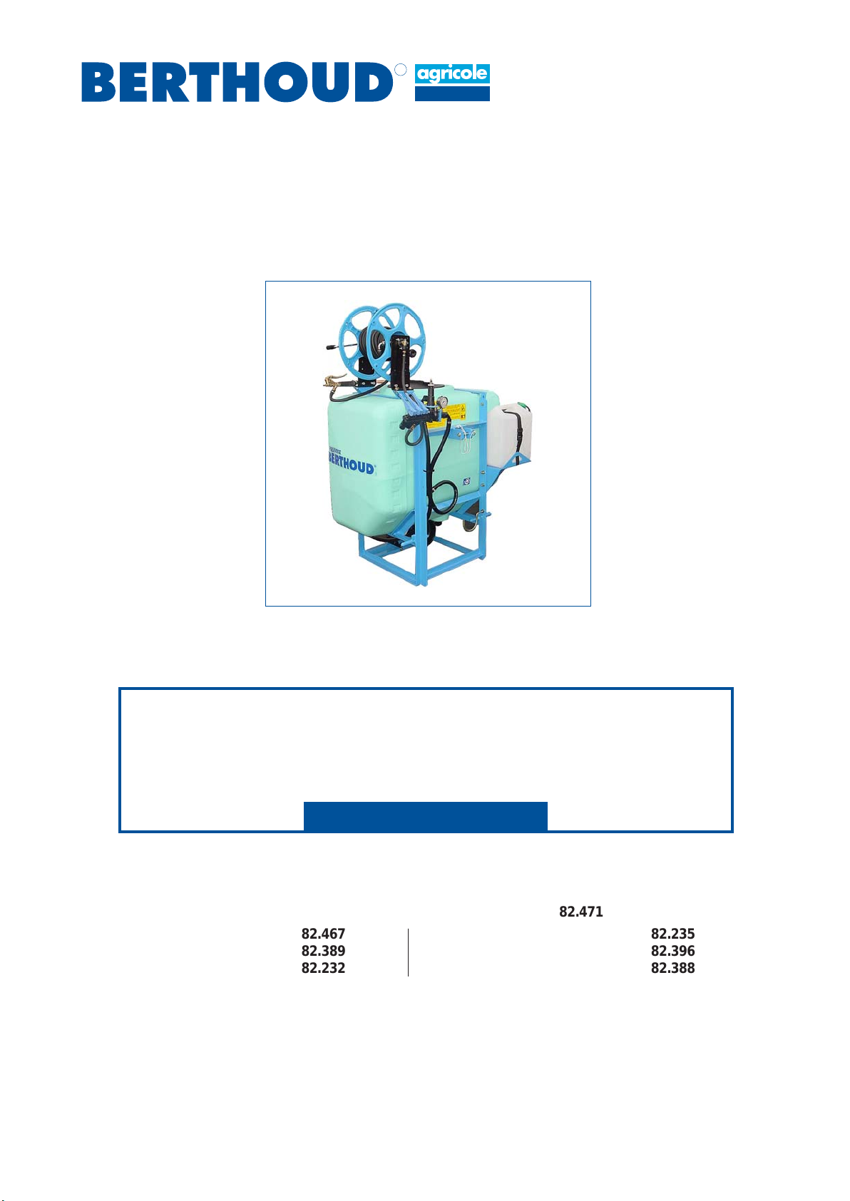
PULVASOL 1 AND 2
PULVIGNE
82.321-M ENGLISH
to be read attentively
and kept for further reference
R
NOZALnozzles: see manual 82.467
BERJUST 2: see manual 82.389
TLP 7 boom: see manual 82.232
Safety, checks, maintenance of the sprayers: see manual 82.471
GC 9 boom: see manual 82.235
XR 12 boom: see manual 82.396
EC 7/9/12 boom: see manual 82.388
© BERTHOUD Agricole 04/2005
82471
82467
82389
82232
82235
82396
82388

282.321-M - Pulvasol 1 and 2 / Pulvigne

3
82.321-M - Pulvasol 1 and 2 / Pulvigne
See pages
- GENERAL AND SAFETY
(See manual No. 82.471)
.Technical specifications............................................................ 7
.Descriptive plate ....................................................................... 8
.Table of weights........................................................................ 8
.Position of the safety stickers ................................................... 9
- STARTING-UP THE SPRAYER
(See manual No. 82.471)
.Rinsing the sprayer before first use .......................................... 12
.
Checks to be carried out every time before the machine is used ....
12
.Calculating boom flow per minute ............................................. 12
- CHOICE OF NOZZLES AND TABLES OF FLOW RATES
(See NOZAL nozzles manual No. 82.467)
- USING THE SPRAYER
(Berjust 2 monitor, see manual No. 82.389)
.Filling ........................................................................................ 14
.Spraying.................................................................................... 16
.Rinsing the equipment .............................................................. 18
.Height of the boom ................................................................... 20
.Stirring ...................................................................................... 20
.Draining the tank....................................................................... 20
- MAINTENANCE OF THE SPRAYER
(See manual No. 82.471)
.Practical recommendations for the servicing of your sprayer ....... 22
.Checks before spray season .................................................... 22
.Maintenance after operation ..................................................... 23
.Winter storage .......................................................................... 23
.Precautions to be taken against frost........................................ 24
.Nozzles or filters dirty................................................................ 24
.Cleaning the filter ...................................................................... 24
.Handwash tank ......................................................................... 24
.Lubrication and greasing........................................................... 26
.Inflation of the air chamber ....................................................... 26
.Operational problems ............................................................... 28
.Product foaming and pressure drop.......................................... 28
- MAINTENANCEDIAGRAMS
.Hydraulic circuit of the PULVASOL sprayer .............................. 30
.Hydraulic circuit of the PULVIGNE sprayer ............................... 32
.Notes on the treatments carried out during the season............. 35
contents

482.321-M - Pulvasol 1 and 2 / Pulvigne

5
82.321-M - Pulvasol 1 and 2 / Pulvigne
Warning.
Acceptable use of the sprayer.
General safety instructions.
Hitching, unhitching.
Maintenance
Adapting the PTO shaft.
Counter-indications.
Meaning of the safety stickers.
See manual "SAFETY, CHECKS, MAINTENANCE" No. 82.471.
GENERAL
AND
SAFETY

682.321-M - Pulvasol 1 and 2 / Pulvigne

7
82.321-M - Pulvasol 1 and 2 / Pulvigne
PULVIGNE
Sprayer
1752
TECHNICAL SPECIFICATIONS
PULVASOL Range
Sprayer with constant pressure control
providing a constant application rate/hectare
for a constant forward speed
- TANK in high density polyethylene of 200/300/400/
600/800 litres capacity.
- STEEL protected by U.H.R. polyester paint.
- FILLING: (see options)
- STIRRING: hydraulicbynon-sprayedliquidreturnto
tank.
- PISTON/DIAPHRAGM PUMP:
- B.P. 60 (60 l/min - 20 bar) or
- B.P. 105 (105 l/min - 20 bar).
- FILTERS:
Suction:
- Filter, mesh 6/10º.
- Valve block comprising:
- a main 1/4 turn valve,
- 3 boom section plugs,
- a pressure regulator,
- a glycerine pressure gauge, 0-25 bars,diameter
60 mm.
- 2 position coupling on 200/300/400 litres.
- Universal joint drive.
- Handwash tank 15 litres capacity.
BOOMS:
TLP 7 metres - GC 9 metres - XRT/XRS T 12 metres.
OPTIONS :
Hose reel,
0.60 m gun with 10 m of hose,
Filling with hydro-injector,
4 or 6 metres filler pipe with strainer,
Independent filling hopper,
Handwash tank 18 litres capacity (except 200 L)
Berjust 2 (in-cab display monitor showing speed and
volume/hectare).
DIMENSIONS
EQUIPMENT A B C
PULVASOL 200 0.80 m 0.51 m 1.22 m
PULVASOL 300 0.85 m 0.75 m 1.25 m
PULVASOL 400 1.10 m 0.75 m 1.25 m
PULVASOL 600 1.30 m 0.90 m 1.40 m
PULVASOL 800 1.77 m 0.95 m 1.60 m
(tank width) (depth) (tank height)
C
B

882.321-M - Pulvasol 1 and 2 / Pulvigne
DESCRIPTIVE PLATE
TABLE OF WEIGHTS
SPRAYERS BOOMS > ECO 9 ECO 12 TLP 7/14 GC 9/18 XRT 12/24 XRST
12/24
Kerb weight 100 120
Gross vehicle
weight 310 320
Kerb weight 135 110 130
Gross vehicle
weight 470 430 450
Kerb weight 140 140 120 130
Gross vehicle
weight 560 560 540 550
Kerb weight 160 160 130 145 260 260
Gross vehicle
weight 790 790 760 775 890 890
Kerb weight 190 190 165 180 295 295
Gross vehicle
weight 1030 1030 1005 1020 1135 1135
PULVASOL 800
Weights in kg
PULVASOL 200
PULVASOL 300
PULVASOL 400
PULVASOL 600
- The location of the descriptive plate on your machine is indicated on the view 3/4 opposite.
- The box "Type" is made up of letters and figures.
- Exemple : PUL M 6 GC 9
Manual, 600 litre PULVASOL,
with a 9 metre GC boom.
The"Kerbweight"and "Gross vehicule weight"boxes
use the data in the table below.
Year of manufacture
The box "No. of series" is made up
of
6 figures.
Example : 95 1042 = order number.
9
82.321-M - Pulvasol 1 and 2 / Pulvigne
417.597
417.579
418.630
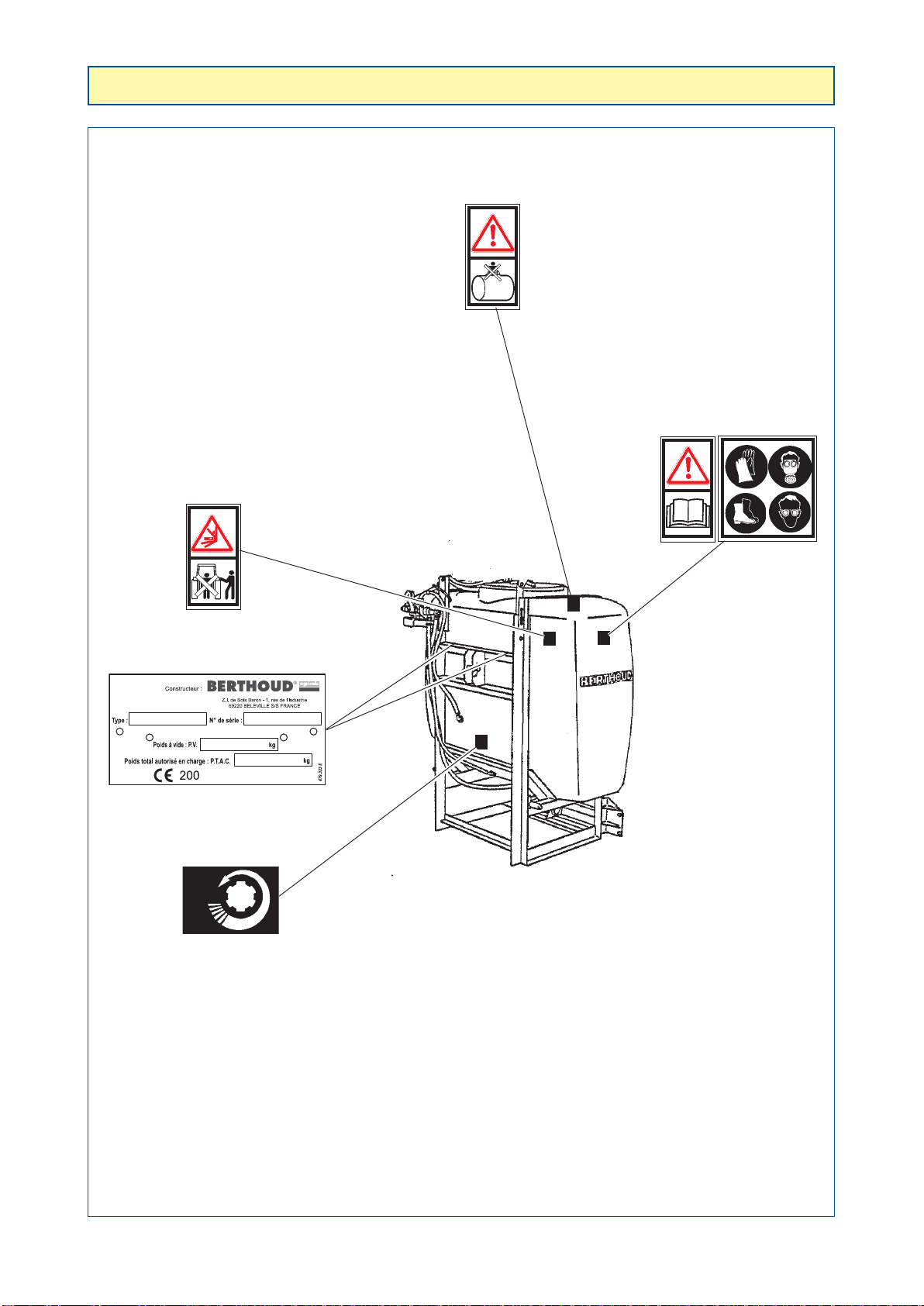
POSITION OF SAFETY STICKERS
417.590
417.572
540
Tmin
Rmin
Umin
Gmin
- PULVASOL -
It is very important that the safety stickers be kept in place and in good
condition as they draw your attention to possible dangers. Refer to the
operator’s manual.
Check their location on the sprayer and refer to Security Manual
No. 82471" for their meaning.

10 82.321-M - Pulvasol 1 and 2 / Pulvigne

11
82.321-M - Pulvasol 1 and 2 / Pulvigne
STARTING-UP
THE SPRAYER
Checking power take-off speed.
Checking forward speed.
Checking engine speed.
Checking flow rate/hectare.
Check of wheel travel distance (Berjust).
See manual "SAFETY, CHECKS, MAINTENANCE" No. 82.471.

12 82.321-M - Pulvasol 1 and 2 / Pulvigne
CALCULATING BOOM FLOW PER MINUTE
To obtain the desired spray configuration, the traditional formula is used:
Boom flow Volume width Advance
x x
hectare treated speed
= -----------------------------------------------
600
Example:
We wish to spray 500 litres/hectare with a 9 metres boom and at a calibrated tractor speed of 6.8 km/h.
We obtain:
- It is most important that maximum pump flow should satisfy the demands made on it for the desired spraying
conditions (advance speed, volume/hectare, width treated).
- The boom flow per minute should be 10 % less than maximum pump flow to ensure liquid return to the tank
and thus hydraulic agitation.
RINSING THE SPRAYER BEFORE FIRST USE
Before using your sprayer for the first time with phytosanitary product
(weedkillers, insecticide or other product), rinse the machine completely.
- Remove the nozzles if they are fitted.
- Undo the end plugs on the pipes.
- Fill 1/5th of the volume of the tank with water.
- Spray (Refer to the pump OPERATION chapter).
- Remove and clean the filters.
- Retighten the pipe end plugs.
- Fit the nozzles.
- Any foreign particles which may be in the spraying circuit will thus be eliminated and there will be no risk of
them blocking the holes in the nozzles.
CHECKS TO BE CARRIED OUT EVERY TIME BEFORE
THE MACHINE IS USED
- Check the condition of the protectors on the drive shafts.
- Make sure that there is no foreign matter in the tank.
- Check the condition of the hoist as well as the boom's lifting rope.
- Check the oil levels and the greasing of the various elements (see "lubrication and greasing" section).
- Check the cleanness filters:
- suction,
- delivery.
500 x 9 x 6.8
= ------------------- = 51 litres/minute
600
Boom flow per minute
Maximum
pump flow Maximum
boom flow Minimum return
flow to tank
Pump
BP 60/20
BP 105/20 60 l/min.
100 l/min. 54 l/min.
90 l/min. 6 l/min.
10 l/min.

13
82.321-M - Pulvasol 1 and 2 / Pulvigne
CHOICE OF NOZZLES
AND
TABLES OF FLOW RATES
USING
THE SPRAYER
See manual No. 82.467
NOZAL nozzles
Berjust 2 monitor option,
see manual No. 82.389

14 82.321-M - Pulvasol 1 and 2 / Pulvigne
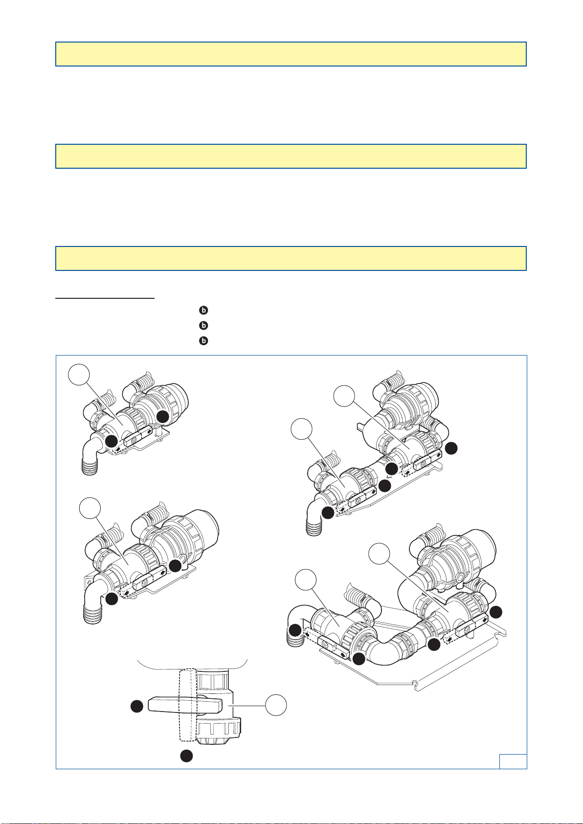
FILLING
- Close the drain valves (see figure 8, page 20)
According to the cases:
- place the valve (V1) in position .
- place the valve (V2) in position .
- place the valve (V4) in position .
OPERATION WITHOUT FILLER PIPE
- Remove the lid on the top of the tank.
- Fill through the filler hole in your tank.
USING THE FILLER PIPE
For this system to work properly, it is necessary to have some water in the tank to prime the pump before
starting it.
- For 30 to 50 litres of water into the filler hole through the filter.
- The filling rate can be increased considerably using the hydro-injector.
SPRAYERS WITH VANNOFILTER (800 L)
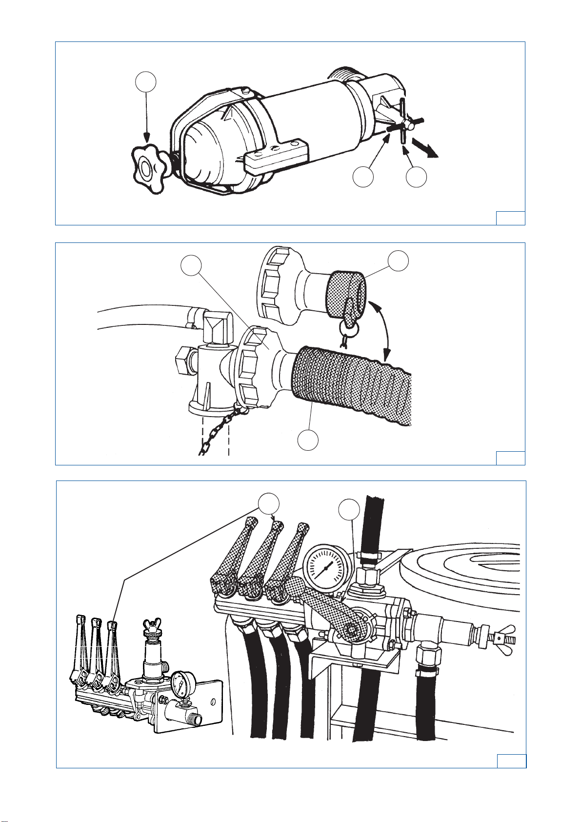
The vannofilter (figure 1) must be open. Check that it is.
- If not: to open it, pull item (1) towards you, then turn it a quarter of a turn to put it in position (2).
- If leaking occurs at the cover, slightly tighten the star-shaped knob (3).
CONNECTING THE FILLER HOSE
-With B.P. pumps (figure 2) :
Connect it directly to the hydro-injector’s (1) suction hose:
- Remove the plug (2) and connect the filler hose (3) in its place.
FILLING
1. Engage the tractor’s power take-off and raise rotation speed to 540 rpm.
2. Your tank will start to fill. Keep the rotation speed of the power take-off at 540 rpm.
3. When filling is complete:
- reduce the engine speed (tick-over),
- take the hose (3) out of the water point. This has the effect of emptying it (3) (figure 2),
- remove the hose (3) from the hydro-injector (1),
- re-fit the plug (2).
ADJUSTING THE CONTROL VALVE (figure 3) :
- With rinsing tank option: place the valves (V3) in position (figure 8, page 20).
- Put the supply plugs on the spray boom sections in position (1).
- Put the handle on the main valve in position (2).
15
82.321-M - Pulvasol 1 and 2 / Pulvigne
3
12
2
12
3
21
3
1

16 82.321-M - Pulvasol 1 and 2 / Pulvigne
OPENING THE VANNOFILTER (case of sprayers with vannofilter) (800 L):
- Make sure that the vannofilter is open (see page 15, figure 1).
POWER TAKE-OFF SPEED:
- With the power take-off connected (following filling), increase its speed to 540 rpm by bringing the needle of
the rev counter opposite the mark (R). (see manual No. 82.471).
ADJUSTING THE VOLUME/HECTARE:
IN ORDER TO PROGRAM YOUR VOLUME/HECTARE
- You need to know, for the gear chosen, the forward speed in km/h, at 540 rpm at the power take-off (see
manual No. 82.471).
- Bearing in mind the required volume/hectare, refer to the rate chart of the selected nozzle(s) (see nozzle
manual No. 82.467).
- Inthe column corresponding to the forward speed in km/h, find: the nozzle andpressurewhichwillenable the
required volume/hectare to be obtained.
Example:
- Speed in km/hour 6 km/h
- Volume/hectare 260 litres/ha
- Selected nozzles ALUMINE AFX (0.50 m spaced).
Possible combinations:
- ALUMINEAFX BLUE ............3.5 bars 256 litres/ha
- ALUMINEAFX RED .................2 bars 258 litres/ha
Youwillchoosethereforeoneoftheabovecoloursdependingontherequirednozzlepressureduringtreatment.
TO OBTAIN REQUIRED VOLUME/HECTARE:
- Fit the chosen nozzles,
- Put the lever on the main valve in position (2), (figure 4)
- Take power take-off speed to 540 RPM.
- Display on the pressure gauge (1) the pressure previously read from the flow rate table, using the nut (3) on
the controller (5) and lock it with the knurled nut (4). (figure 4)
- From now on, you can work.
SPRAYING:
- With rinsing tank option: place the valves (V3) in position (figure 8, page 20).
- Set the stopper controlling supply to boom sections in position (1) (figure 5).
- Put the lever on the main valve in position (4) (figure 5).
TO STOP SPRAYING
Total closure:
- Leave the shut-offs in the "OPEN" position (1) and adjust the main valve, putting its handle in position (3)
(figure 5).
Closure of one or more sections:
- Close the plug or plugs by putting them in position (2).
- All the liquid comes out through the top of the valve and returns directly to the tank, or passes through the
hydro-injector (machines with a hydro-injector), thus continuing the agitation of the spraying mixture, but
without passing through the controller.
SPRAYING

17
82.321-M - Pulvasol 1 and 2 / Pulvigne
12
3
4
5
4
3
2
1
4
5

18 82.321-M - Pulvasol 1 and 2 / Pulvigne
RINSING THE EQUIPMENT
RINSING THE SPRAYING CIRCUIT WITH THE RINSING TANK
- Sprayer off.
- Disconnect the power take-off.
- Plugs (1) in position , (figure 6).
- Valve (2) in position (figure 6).
- Valves (V2) in position (figure 7) (600 L).
- Valves (V3) in position (figure 7) (600 L).
- Valves (6) in position (figure 7) (800 L).
- Run at low speed at 150 rpm max.
- Engage the tractor power take-off and run until the rinsing tank is empty.
This operation is not sufficient for a product change.
RINSING THE SPRAYING CIRCUIT WITH THE MAIN TANK
In the case of a product change.
- Sprayer off.
- Put 300 litres of clear water into the main tank with a ALL CLEAR type cleaning product.
- Plugs (1) in position , (figure 6).
- Valve (2) in position (figure 6).
With rinsing tank option:
- Valves (V2) in position (figure 7) (600 L).
- Valves (V3) in position (figure 7) (600 L).
- Valves (6) in position (figure 7) (800 L).
- Run at low speed at 150 rpm max.
- Engage the tractor power take-off and run until the tank is empty.

19
82.321-M - Pulvasol 1 and 2 / Pulvigne
a
a
b
b
a
a
a
b
b
b
a
a
b
b
cuve
principale
cuve de
rin
ç
age
(600L)
(800L)
6
2
7
1
V2
V3
V2 V3
6Main tank
Rinsing tank
20 82.321-M - Pulvasol 1 and 2 / Pulvigne
- 50 cm to 80 cm above the surface to be treated depending on the spray angle of the nozzles and their
spacing.
If the boom is higher, there is a risk of drift.
HYDRAULIC STIRRING:
- The pump has a fixed output. This output supplies the spray boom. The surplus goes back to the tank via the
flow regulating valve. It is this surplus which provides hydraulic agitation.
HEIGHT OF THE BOOM
STIRRING
DRAINING THE TANK
a
a
b
b
a
ba
a
b
b
a
b
a
b
According to the cases:
- Place the valve (V1) in position .
- Place the valve (V2) in position .
- Place the valve (V4) in position .
8
V1
V2
V3
V2
V3
V1
V4
This manual suits for next models
8
Table of contents
Other Berthoud Paint Sprayer manuals

Berthoud
Berthoud MAXAIR 240 User manual

Berthoud
Berthoud ELYTE 2 360 EPDM User manual

Berthoud
Berthoud WIN'AIR 600 User manual

Berthoud
Berthoud ALTO 300 User manual

Berthoud
Berthoud ULV User manual

Berthoud
Berthoud VERMOREL 3000 ELECTRIC User manual

Berthoud
Berthoud RAPTOR 2540 User manual

Berthoud
Berthoud ELYTE 2 VITON User manual

Berthoud
Berthoud VERMOREL 3000 ELECTRIC User manual

Berthoud
Berthoud VANTAGE E.C.TRONIC 28-30 User manual


