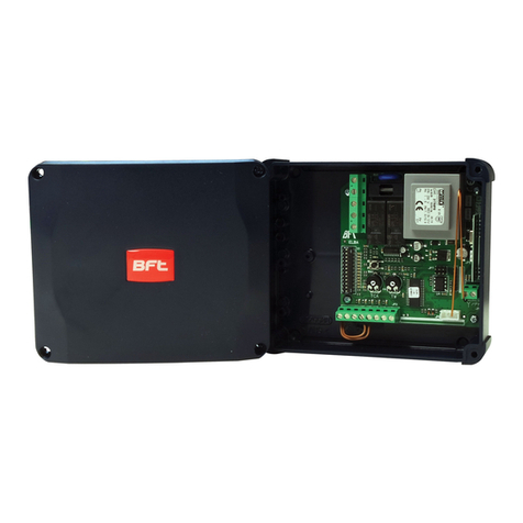
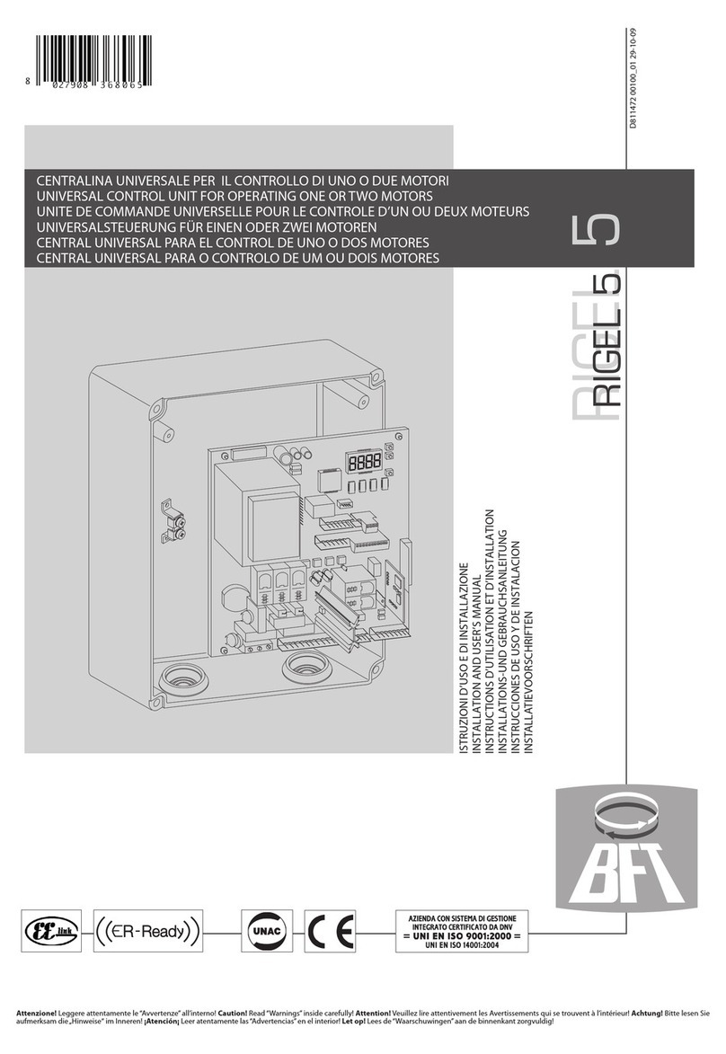
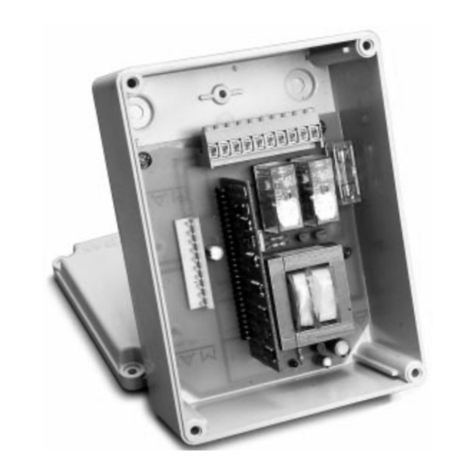
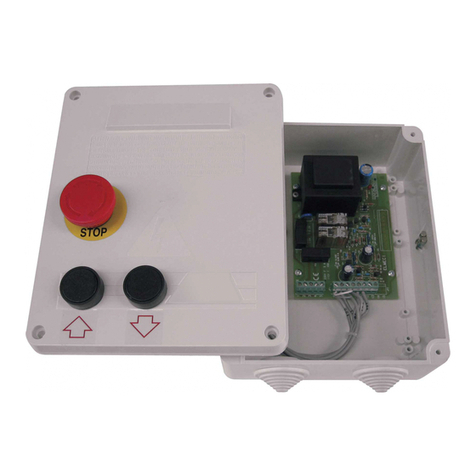
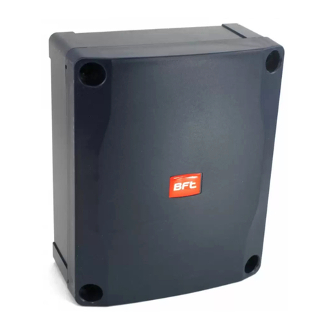
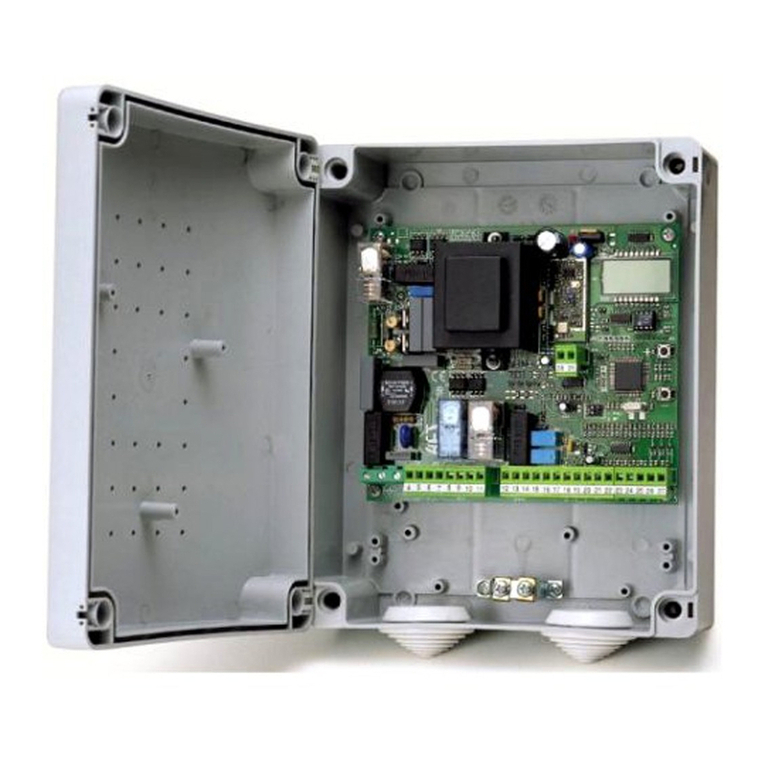
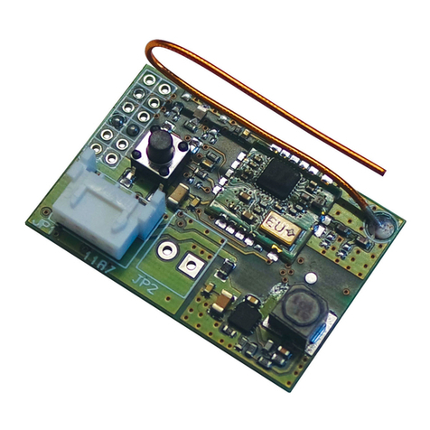
BFT POLLUCE 2M User manual

I
ISTRUZIONI
INSTRUCTIONS
INSTRUCTIONS
MONTAGEANLEITUNG
INSTRUCCIONES
GB
F
D
E
CENTRALINA DI COMANDO
CONTROL UNIT
UNITÉ DE COMMANDE
STEUERUNG
CENTRAL DE MANDOS
CENTRAL DE COMANDO
POLLUCE 2M-2E
D811199A ver.02 10-07-00
P
8 027908 113931

2 - D811199A Ver. 02
Nel ringraziarVi per la preferenza accordata a questo prodotto, la
ditta ècerta che da esso otterrete le prestazioni necessarie al Vostro
uso. Leggete attentamente l'opuscolo "AVVERTENZE" ed il "LI-
BRETTO ISTRUZIONI" che accompagnano questo prodotto in quanto
forniscono importanti indicazioni riguardanti la sicurezza, l'installa-
zione, l'uso e la manutenzione.
Questo prodotto risponde alle norme riconosciute della tecnica e della
disposizioni relative alla sicurezza . Confermiamo che èconforme alle
seguenti direttive europee: 89/336/CEE, 73/23/CEE (modificato da RL
91/263/CEE, 92/31/CEE e 93/68/CEE).
1) GENERALITÀ
La centralina Mod. POLLUCE 2M èadatta a comandare 1 o 2
operatori della serie ARM2, progettati per automatizzare basculanti
di vario tipo. La centralina puòessere:
-Presente a bordo della serie ARM2 (fig.1)
-Montata su quadro a parete (fig.2) da utilizzare per la serie
senza centralina a bordo ( serie ARM2-SQ).
Nel caso si voglia automatizzare una basculante con due motori,
sono possibili 2 configurazioni:
- n°1 ARM2 + n°1 ARM2-SQ
- n°2 ARM2-SQ + n°1 POLLUCE 2M con quadro,montata a parete
2) DATI TECNICI
Tensione di alimentazione: 230V±6% 50/60Hz (*)
Corrente a vuoto: 150mA (varia con accessori)
Potenza max. assorbita: 300W per motore
Alimentazione accessori: 24Vac ±20%
Corrente max per accessori: 0.25A (6VA)
Temperatura di utilizzo: -20 +60C°
Max n°manovre in 24h: 40
Tempo di chiusura autom. TCA regolabile 0÷90 sec
Tempo di lavoro TW regolabile 0÷40 sec
Luce di cortesia temporizzata: 230V - 25W max - 90sec.
Lampeggiante: 230V - max 40W
(*)Per alimentazione a 110V vedere valori fusibili in fig.1 - 2.
3) LOGICA DI FUNZIONI
START: logica a quattro passi (DIP5 OFF)
cancello chiuso: apre
in apertura: ferma ed inserisce il TCA se configurato
cancello aperto: chiude
in chiusura: ferma e non inserisce il TCA
dopo stop: va in apertura
START: logica a due passi: (DIP5 ON)
porta chiusa: apre
in apertura: ferma ed inserisce il TCA se configurato
porta aperta: chiude
in chiusura: apre
dopo stop: apre
STOP: Arresto. Arresta il cancello fino a nuovo start
PHOT: Ingresso fotocellule configurabile tramite il DIP3
SWO: A finecorsa apertura arresta la porta
SWC: A finecorsa chiusura arresta la porta
SCA: Spia porta aperta
con porta chiusa: spenta
con porta in apertura: accesa
con porta aperta: accesa
con porta in chiusura: lampeggiante
4) SELEZIONE DIP-SWITCH
DIP1 Chiusura Rapida (SCL)
ON: Quando si transita attraverso le fotocellule, sia in entrata che che
in uscita, all'ultimo disimpegno delle fotocellule,la porta si richiude
automaticamente senza attendere la fine del TCA. Si consiglia di
utilizzare questa funzione, qualora le condizioni di sicurezza dell'instal-
lazione per mettano di configurare il DIP3-ON (fotocellule attive solo
in chiusura).
OFF: Funzione disattiva.
DIP2:Blocca impulsi in apertura (IBL)
ON: Durante la fase di apertura non accetta comandi di START.
OFF: Durante la fase di apertura accetta comandi di START.
DIP3:Fotocellule in apertura (FCH)
ON: Fotocellule attive solo in chiusura.
OFF: Fotocellule attive in chiusura ed apertura.
DIP4:Tempo di chiusura automatica (TCA)
ON: Tempo di chiusura automatica inserita
(regolabile da 0 a 90sec con Trimmer TW).
OFF :Tempo di chiusura automatica escluso.
DIP5:Logica di comando (2P/4P)
ON: Attiva logica a 2 passi (vedere paragrafo start).
OFF Attiva logica a 4 passi (vedere paragrafo start).
DIP6:Non utilizzato (Lasciare sempre in OFF).
5) REGOLAZIONE TRIMMER
TCA Regola il tempo di chiusura automatica, trascorso il quale, la
porta si chiude automaticamente (regolabile da 0 a 90sec).
TW Regola il tempo di lavoro del motore, trascorso il quale, il motore
si ferma (regolabile da 0 a 40sec).
Permette di fermare il motore nel caso che, per qualche motivo, non
venga intercettato il micro di finecorsa.
6) REGOLAZIONE COPPIA MOTORE
La scheda mod.POLLUCE 2M èalimentata da un trasformatore che
permette anche di selezionare la coppia elettrica del motore.
PERICOLO: Ai morsetti del trasformatore, è presente alimenta-
zione di rete. Togliere l'alimentazione di rete per qualsiasi inter-
vento all'installazione. Per selezionare la presa di coppia, togliere
la protezione al trasformatore e ricordarsi di riposizionarla.
La selezione si effettua spostando il collegamento "55" del trasforma-
tore in una delle 4 prese "T1-T2-T3-T4" come indicato in fig.1 -2.
Nel caso la basculante presenti eccessivi attriti, individuabili dallo
sforzo necessario per aprire manualmente la porta, verificare il
bilanciamento o eseguire la manutenzione necessaria per eliminarli.
ATTENZIONE: Una selezione di coppia eccessiva, può compro-
mettere la sicurezza antischiacciamento.
Al contrario, una regolazione di coppia insufficiente, può non
garantire una corsa di apertura o chiusura corretta.
7) COLLEGAMENTI MORSETTIERA POLLUCE 2M (fig.3)
JP14
1-10 Alimentazionemonofase230V±6%,50-60Hz.(1=L /10=N)
2-5 Non utilizzati
3-4 Condensatore motore M1
11-12-13 Collegamento motore M1 (12 comune, 11-13 marcia)
6-7 Condensatore motore M2
14-15-16 Collegamento motore M2 (15 comune, 14-16 marcia)
8-17 Collegamento luce di cortesia temporizzata (max25W)
9-18 Collegamento lampeggiante 230V (max 40W)
JP7
25 Comune comandi (equivalente al morsetto 19)
19-20 Pulsante Start ( apre-chiude N.O.)
19-26 Pulsantediblocco(N.C.).Senonsiusalasciareponticellato.
19-21 Ingresso fotocellula o costa sensibile (N.C.)
Se non si usa lasciare ponticellato
19-22 Collegamento micro finecorsa Chiusura (SWC)
19-27 Collegamento micro finecorsa Apertura (SWO)
28-23 Uscita24Vac 0.25Amax (6VA) (alimentazione fotocellula
o altri dispositivo)
23-29 Spia segnalazione cancello aperto 24V (max 3W)
24-30 Ingresso antenna per scheda radioricevente (24 segna
le - 30 calza)
JP1
Connettore scheda radioricevente. 1-2 canali
JP8
Uscita secondo canale radio della scheda ricevente
bicanale (non montato) (contatto puro N.O.)
8) COLLEGAMENTI MORSETTIERA POLLUCE 2E (fig.4)
Édisponibile anche una versione con possibilitàdi collegare una
elettroserratura a 12V.
Questa versione si identifica per il nome POLLUCE 2E.
In fig.4, èriportata solo la parte di morsettiera che interessa il collega-
mento dell' elettroserratura. Fare riferimento alla morsettiera di fig.3
per tutti gli altri collementi.
I

D811199A Ver. 02 - 3
Thank you for buying this product, our company is sure that you will be
more than satisfied with the performance of the product.
This product is supplied with a “WARNINGS”leaflet and an
“INSTRUCTION MANUAL”. These should both be read carefully as
they provide important information about safety, installation,
operation and maintenance.
This product complies with recognized technical standards and safety
regulations. We declare that this product is in conformity with the
following European Directives: 89/336/EEC and 73/23/EEC (amended
by RL 91/263/EEC, 92/31/EEC and 93/68/EEC).
1) GENERAL OUTLINE
The POLLUCE 2M Mod. Unit is suitable for operating 1 or 2 ARM2
series controllers, and has been designed to automate various types of
overhead doors.
The unit can be: Included with the ARM2 series (fig. 1).
Fitted onto a wall panel (fig. 2) for use with the series without the control
unit (ARM2-SQ series). 2 possible configurations are available in case
two-motor overhead door automation is required:
No. 1 ARM2 + No. 1 ARM2-SQ.
No. 2 ARM2-SQ + No. 1 2M POLLUCE with panel, wall-mounted.
2) TECHNICAL SPECIFICATIONS
Power supply voltage: 230V±6% 50/60Hz (*)
No load current: 150 (varies depending
on accessories)
Max. absorbed rating: 300W for motor
Power supply to accessories: 24Vac ±20%
Max. current for accessories: 0.25A (6VA)
Working temperature: -20°+60°C
Max. No. of manoeuvres in 24h: 40
Automatic closing time TCA: adjustable 0 - 90 sec
Operation time TW: adjustable 0 - 40 sec
Time-set courtesy light: 230V - 40W max. 90 sec
Blinker: 230V - 40W max.
(*) For 110V power supply see fuse values in figs. 1 - 2.
3) FUNCTION LOGIC
START: four-step logic: (DIP5 OFF)
gate closed: opens
on opening: stops and inserts TCA if configured
gate opened: closes
on closing: stops but will not insert TCA
after stopping: moves to open
START: two-step logic: (DIP5 ON)
door closed: opens
on opening: stops and inserts TCA if configured
door opened: closes
on closing: opens
after stopping: opens
STOP: Stops the gate until restart
PHOT: Photocell input
Configured by means of DIP3
SWO: Stops door at end of opening stroke
SWC: stops door at end of closing stroke
SCA: Door open warning light
with door closed: off
with door opening: on
with door opened: on
with door closing: blinking
4) DIP-SWITCH SELECTION
DIP1: Swift Closure (SCL)
ON: When there is movement across the photocells, either on entry
or on exit, at the last disengagement of the photocells, the door closes
automatically without waiting for the TCA to end. This function is
recommended whenever the safety conditions of the installation allow
the configuration of DIP3-ON (the photocells are only active on closing).
OFF: Function deactivated.
DIP2:Blocks impulses on opening (IBL)
ON: Will not accept START commands during opening phase.
OFF: Accepts START commands during opening phase.
DIP3:Photocell on opening (FCH)
ON: Photocell is only active on closing.
OFF: Photocell is active both on closing and opening.
DIP4:Automatic closing time (TCA)
ON: Automaticclosingtimeinserted(adjustable0-90secwithtrimmerTW).
OFF: Automatic closing time excluded.
DIP5:Control logic (2P/4P)
ON: Activates two-step logic (see paragraph on start).
OFF: Activates four-step logic (see paragraph on start).
DIP6:Not used (always leave OFF).
5) TRIMMER ADJUSTMENT
TCA Sets the automatic closing time, after which the door
closes automatically (adjustable from 0 to 90 sec).
TW Sets the motor operating time, after which the motor stops
(adjustable from 0 to 40 sec). Allows the motor to be stopped in the
case where, for any reason, the limit microswitch is not detected.
6) MOTOR TORQUE SETTING
The POLLUCE 2M mod. board is supplied by a transformer which also
allows the electric motor torque to be selected.
DANGER: The transformer terminals are connected to the mains
power supply. Disconnect the mains power supply before doing
any work on the installation. To select the torque tap, remove the
transformer protection and remember to replace it afterwards.
Theselection is carried out bymoving connection “55”of the transformer
to one of the 4 taps “T1 - T2 - T3 - T4”as shown in figs. 1 -2.
In the case where the overhead door produces excessive friction,
which can be detected by the force required to open the door
manually, check the balancing or carry out the necessary maintenance
to eliminate it.
WARNING: Excessive torque adjustment may jeopardize the anti-
squash safety function.
Ontheotherhandinsufficienttorque adjustment may not guarantee
correct opening or closing strokes.
7) POLLUCE 2M TERMINAL BOARD CONNECTIONS (fig. 3)
JP14
1-10 Single phase power supply 230V±6% 50/60Hz (1=L/10=N)
2-5 Not used
3-4 M1 motor capacitor
11-12-13 M1 Motor connection (12 common, 11-13 run)
6-7 M2 motor capacitor
14-15-16 M2 motor connection (15 common, 14-16 run)
8-17 Time-set courtesy light connection (25W max.)
9-18 Blinker connection 230V (40W max.)
JP7
25 Control common terminal (corresponding to terminal 19)
19-20 Start button (opens - closes N.O.)
19-26 Lock button (N.C.). When not used leave bridged.
19-21 Electric edge or photocell input (N.C.).
When not used leave bridged.
19-22 Closing limit microswitch connection (SWC)
19-27 Opening limit microswitch connection (SWO)
28-23 24 Vac 0.25A max. (6VA) outlet (power supply to
photocell or other devices)
23-29 Gate open warning light 24V (3W max.)
24-30 Antenna input for radio receiver board (24 signal - 30 braid).
JP1
Radio receiver board connector. 1-2 channels.
JP8
Second radio channel output from the double-channel
receiving board (not fitted) (dry contact N.O.)
8) POLLUCE 2E TERMINAL BOARD CONNECTIONS (fig. 4)
Another version is also available which allows the connection of a 12V
electric lock. This version is known as POLLUCE 2E.
Fig. 4 only shows the part of the terminal board regarding the electric
lock connection. For all other connections, reference should made to
the terminal board in fig. 3.
GB

4 - D811199A Ver. 02
F
Nous vous remercions pour avoir choisi ce produit. Nous sommes
certains qu’il vous offrira les performances que vous souhaitez.
Lisez attentivement la brochure “AVERTISSEMENTS”et le “MANUEL
D’INSTRUCTIONS”qui accompagnent ce produit, puisqu’ils
fournissent d’importantes indications concernant la sécurité,
l’installation, l’utilisation et l’entretien.
Ce produit est conforme aux règles reconnues de la technique et aux
dispositionsdesécurité.Nouscertifionssaconformitéaveclesdirectives
européennes suivantes: 89/336/CEE, 73/23/CEE (amendée par les
directives RL 91/263/CEE, 92/31/CEE et 93/68/CEE).
1) GENERALITES
La centrale mod. POLLUCE 2M est indiquée pour commander 1 ou 2
opérateurs de la série ARM2, conçus pour automatiser des portes de
garage de plusieurs types. La centrale peut être:
Comprise dans la série ARM2 (fig. 1)
Montée sur tableau mural (fig. 2) àutiliser pour la série sans centrale
montée (série ARM2-SQ).
Si on veut automatiser une porte de garage avec deux moteurs, deux
configurations sont possibles:
n°1 ARM2 + n°1 ARM2-SQ
n°2 ARM2-SQ + n°1 POLLUCE 2M avec tableau, montage mural.
2) CARACTERISTIQUES TECHNIQUES
Tension d’alimentation: 230V ±6% 50/60Hz (*)
Courant à ide: 150 mA (différente en
cas d’accessoires)
Puissance max. absorbée: 300W pour moteur
Alimentation accessoires: 24 Vc.a. ±20%
Courant maxi pour accessoires: 0,25A (6VA)
Température d’utilisation: -20 +60°C
N° maxi de manoeu res en 24h: 40
Temps de fermeture automatique TCA: réglable 0÷90 s
Temps de tra ail TW: réglable 0÷40 s
Lumière de courtoisie temporisée: 230V - 24W maxi - 90 s.
Feu clignotant: 230V - 40W maxi
(*) Pour l’alimentation à110V voir les valeurs des fusibles des fig. 1 - 2.
3) LOGIQUE DE FONCTIONS
START: logique à quatre pas (DIP5 OFF)
porte fermée: ouvre
en ouverture: arrête et active le TCA, si
configuré
porte ouverte: ferme
en fermeture: arrêteetn’activepasleTCA
après stop: va en ouverture
START: logique à deux pas (DIP5 ON)
porte fermée: ouvre
en ouverture: ferme et active le TCA si
configuré
porte ouverte: ferme
en fermeture: ouvre
après stop: ouvre
STOP: Arrêt. Arrête la porte jusqu’à un nouveau start.
PHOT: Entrée cellules photoélectriques.
Configurable avec le DIP 3.
SWO: A la fin de course ouverture, arrête la porte.
SWC: A la fin de course fermeture, arrête la porte.
SCA:Témoin de porte ouverte.
avec porte fermée: éteint
avec porte en ouverture: allumé
avec porte ouverte: allumé
avec porte en fermeture: clignotant
4) SELECTION DES INTERRUPTEURS DIP
DIP1 Fermeture rapide (SCL)
ON: Lorsque l’on passe àtravers les cellules photoélectriques, tant à
l’entrée qu’à la sortie, lors du dernier dégagement des cellules
photoélectriques la porte se referme automatiquement sans attendre
la fin du TCA. Il est conseilléd’utiliser cette fonction si les conditions de
sécuritéde l’installation permettent de configurer l’interrupteur DIP3
sur ON (cellules photoélectriques actives seulement en fermeture).
OFF: Fonction inactive.
DIP2 Bloque les impulsions en ouverture (IBL)
ON: Pendant la phase d’ouverture, n’accepte pas des commandes
de START.
OFF: Pendant la phase d’ouverture, accepte des commandes
de START.
DIP3 Cellule photoélectriques en ouverture (FCH).
ON: Cellules photoélectriques actives seulement en fermeture.
OFF: Cellules photoélectriques actives en fermeture et en ouverture.
DIP4 Temps de fermeture automatique (TCA)
ON: TCA Temps de fermeture automatique actif (réglable de 0 à90
s avec condensateur d’équilibrage TW).
OFF: Temps de fermeture automatique non actif.
DIP5 Logique de commande (2P/4P)
ON: Active la logique à2 pas (voir paragraphe START).
OFF: Active la logique à4 pas (voir paragraphe START).
DIP6 Non utilisé(Laisser toujours sur OFF).
5) REGLAGE DES CONDENSATEURS D’EQUILIBRAGE
TCA Règle le temps de fermeture automatique après lequel la porte
se ferme automatiquement (réglable de 0 à90 s).
TW Règle le temps de travail du moteur après lequel le moteur
s’arrête (réglable de 0 à40 s). Permet d’arrêter le moteur si, pour
n’importe quelle raison, le micro de fin de course n’était pas intercepté.
6) REGLAGE DU COUPLE MOTEUR
La carte mod. POLLUCE 2M est alimentée par un transformateur qui
permet aussi de sélectionner le couple électrique du moteur.
DANGER:Danslesbornes du transformateur il y a de l’alimentation
de ligne. Couper l’alimentation de ligne pour toute intervention
d’installation. Pour sélectionner la prise de couple, enlever la
protection au transformateur et se rappeler de la remettre en place.
La sélection se fait en déplaçant la connexion “55”du transformateur
dans l’une des 4 prises “T1-T2-T3-T4”, comme indiquédans les fig. 1 - 2.
Si la porte présente trop de frottements, pouvant être déterminés par
l’effortnécessaire pour ouvrir manuellement la porte, vérifier l’équilibrage
ou effectuer l’entretien nécessaire pour les éliminer.
ATTENTION: Un réglage de couple excessif peut compromettre la
sécurité anti-écrasement. Au contraire, un réglage de couple
insuffisant peut ne pas assurer une course d’ouverture ou de
fermeture correcte.
7) CONNEXIONS BORNIER POLLUCE 2M (fig. 3)
JP14
1-10 Alimentation monophasée 230V ±6%, 50/60 Hz (1=L/10=N)
2-5 Non utilisées
3-4 Condensateur moteur M1
11-12-13 Connexion moteur M1 (12 commune, 11-13 marche)
6-7 Condensateur moteur M2
14-15-16 Connexion moteur M2 (15 commune, 14-16 marche)
8-17 Connexion lumière de courtoisie temporisée (25W maxi)
JP7
25 Commune commandes (équi alente à la borne 19)
19-20 Bouton Start (ou re-ferme NO)
19-26 Bouton de blocage (NF). En cas de non utilisation laisser
connecté pro isoirement.
19-21 Entrée cellule photoélectrique ou barre palpeuse sensible
(NF). En cas de non utilisation laisser connecté pro isoirement.
19-22 Connexion micro fin de course Fermeture (SWC)
19-27 Connexion micro fin de course Ou erture (SWO)
28-23 Sortie 24 Vc.a. 0,25A maxi (6VA) (alimentation cellule
photoélectrique ou autres dispositifs)
23-29 Témoin signalisation porte ou erte 24V (3W maxi)
24-30 Entrée antenne pour carte radioréceptrice (24 signal - 30 gaine)
JP1
Connecteur carte radioréceptrice 1-2 canaux.
JP8
Sortie deuxième canal radio de la carte réceptrice bicanal
(non monté), (contact pur NO).
8) CONNEXIONS BORNIER POLLUCE 2E (fig. 4)
Est disponible aussi une version avec possibilitéde connecter une
serrure électrique à12V. Cette version est identifiée par le nom
POLLUCE 2E.
La fig. 4 illustre seulement la partie de bornier concernant la connexion
de la serrure électrique. Se référer au bornier de la fig. 3 pour toutes les
autres connexions.

D811199A Ver. 02 - 5
D
Indem wir Ihnen für den Vorzug danken, den Sie diesem Produkt
entgegengebracht haben, ist die Firma sicher, daßSie von diesem die
für Ihren Gebrauch notwendigen Leistungen erhalten werden.
Lesen Sie aufmerksam die Broschüre “WARNUNGEN”und die
“GEBRAUCHSANWEISUNG”, die diesem Produkt beigelegt sind und
die wichtige Hinweise betreffend die Sicherheit, die Installation, den
Gebrauch und die Wartung liefern.
Dieses Produkt entspricht den anerkannten Regeln der Technik und
der Sicherheitsvorkehrungen. Wir bestätigen, daßes den folgenden
europäischen Vorschriften entspricht: 89/336/EWG, 73/23/EWG
(geändert durch die Richtlinien 91/263/EWG, 92/31/EWG und 93/68/
EWG).
1) ALLGEMEINES
Die Steuerung Mod. POLLUCE 2M ist den Betrieb von einem oder zwei
Antrieben der Serie ARM2 geeignet, die für die Automatisierung von
Kipptore verschiedener Typen geplant wurden. Die Steuerung kann
wie bolgt untergebracht werden:
- am Antrieb selber, bei Mod. ARM2 (Fig. 1)
-für Wandmontage (Fig. 2), bei Mod.ARM2 SQ ohne Steuerung
Für den Fall, das man ein Garagen Kipptor mit zwei Antrieben
automatisieren will, sind zwei zusammenstellungen möglich:
1Stk ARM2 + 1Stk ARM2-SQ oder
2 Stk ARM2-SQ + 1Stk POLLUCE 2M Steuerung für Wandmontage.
2) TECHNISCHE DATEN
Betriebsspannung: 230V ±6% 50/60Hz (*)
Leerlaufstrom: 150 mA(variiert mit dem Zubehör)
Höchstlast des Motors: 2 x 300W
Speisung der Zubehörteile: 24Vac ±20%
Spitzenstrom für Zubehörteile: 0.25A (6VA)
Betriebstemperatur: -20 bis +60°C
Max. Anzahl der Vorgänge in 24 Std.: 40
Automatische Schließzeit TCA: einstellbar 0 ÷90 Sek.
Lauf TW: einstellbar 0 ÷40 Sek.
Zeitgesteuertes Innenlicht: 230V - 25W max. - 90 Sek.
Blinkleuchte: 230V - max 40W
(*) Bezüglich der Speisung mit 110V siehe Absicherung in Fig.1 - 2
3) FUNKTIONSLOGIK
START: Vier-Schritt-Logik: (DIP5 OFF)
Tor geschlossen: öffnet
in Öffnung: hält an und schaltet die TCA
ein, soweit aktiviert
Tor geöffnet: schließt
in Schließung: hält an und schaltet TCA
nicht ein
nach Stop: geht in Öffnung
START: Zwei-Schritt-Logik: (DIP5 ON)
Tor geschlossen: öffnet
in Öffnung: hält an und schaltet die
TCA ein, soweit aktiviert
Tor offen: schließt
in Schließung: öffnet
nach Stop öffnet
STOP: Anhalten. Hält das Tor bis zu neuem Start an.
PHOT: Eingang Lichtschranken wählbar mittels DIP3
SWO: Bei Ende des Öffnungsvorganges bleibt das Tor stehen
SWC: Bei Ende des Schließvorganges bleibt das Tor stehen.
SCA: Kontrolleuchte “Tor geöffnet” bei geschlossenem
Tor: aus
beim Öffnungsvorgang: an
bei geöffnetem Tor: an
beim Schließvorgang : blinkend
4) DIP-SCHALTER-EINSTELLUNG
DIP1: Schnellschließung (SCL)
ON Wenn man die Lichtschranke sowohl beim Eintritt als auch beim
Austrittvollständig durchschritten hat, schließt sich dasTor automatisch
wieder, ohne das Ende der TCA abzuwarten. Es wird empfohlen, diese
Funktion zu benutzen, falls die Sicherheitsbedingungen der Anlage die
Aktivierung des DIP3-ON erlauben (Lichtschranken nur beim
Schließvorgang aktiv).
OFF: Funktion deaktiviert.
DIP2:Blockiert die Impulse beim Öffnungsvorgang (IBL)
ON: Nimmt während der Öffnungsphase keine START-Befehle an.
OFF: Nimmt während der Öffnungsphase START-Befehle an.
DIP3:Lichtschranken beim Öffnungsvorgang (FCH)
ON: Lichtschranken nur beim Schließvorgang aktiviert.
OFF: Lichtschranken beim Öffnungs- und Schließvorgang aktiviert.
DIP4:Dauer der automatischen Schließung (TCA)
ON: Automatische Schließzeit aktiviert (einstellbar von 0 bis 99 Sek.
mit Trimmer TW)
OFF: Automatische Schließzeit nicht aktiviert.
DIP5:Steuerlogik (2S/4S)
ON: 2-Schritt-Logik ist aktiviert (siehe Absatz Start).
OFF: 4-Schritt-Logik ist aktiviert (siehe Absatz Start).
DIP6:Nicht verwendet (Immer auf OFF stehen lassen)
5) EINSTELLUNG TRIMMER
TCA Stellt die automatische Schließzeit ein, nach deren Ablauf sich
das Tor automatisch schließt. (einstellbar von 0 bis 90 Sek.).
TW Stellt die Betriebszeit des Motors ein, nach deren Ablauf der Motor
abschaltet (einstellbar von 0 bis 40 Sek.). Erlaubt die Abschaltung des
Motors, falls aus irgendeinem Grund der Endschalter nicht erfasst wird.
6) EINSTELLUNG DES MOTORDREHMOMENTS
Die Steuerung Mod. POLLUCE 2M ist mit einem Transformator
versehen,derauch die Einstellung des elektrischen Motordrehmoments
erlaubt.
GEFAHR: An den Transformatorklemmen ist Netzspannung
vorhanden. Für jeden Eingriff in die Anlage die Netzspannung
ausschalten. Um die Drehmomentssteckdose einzustellen, den
Schutz am Transformator abnehmen und daran denken, ihn
wieder anzubringen.
Die Einstellung wird durchgeführt, indem die Verbindung “55”des
Transformators in eine der 4 Abgriffe “T1-T2-T3-T4”- wie in Fig. 1 - 2
gezeigt - umgesteckt wird.
Falls das Kipptor zuviel Reibung aufweist, was der notwendigen
Anstrengung zur manuellen Öffnung des Tores zu entnehmen ist, die
Auswuchtung überprüfen oder die notwendige Wartung zu ihrer
Beseitigung durchführen.
ACHTUNG: Eine übermäßige Einstellung des Drehmoments kann
die Quetschungsgefahr erhöhen.
Andererseits kann eine unzureichende Einstellung des
Drehmoments keinen korrekten Ablauf des Öffnungs- oder
Schließungsvorganges garantieren.
7) ANSCHLÜSSE KLEMMBRETT POLLUCE 2M (Fig. 3)
JP14
1-10 Einphasig e Betriebsspannung 230V ±6% 50/60Hz (1=L/10=N)
2-5 Nicht benutzt
3-4 Kondensator Motor M1
11-12-13 AnschlußMotor M1 (12 gemeinsam, 11-13 Betrieb)
6-7 Kondensator Motor M2
14-15-16 AnschlußMotor M2 (15 gemeinsam, 14-16 Betrieb)
8-17 Anschlußzeitgesteuerte Innenleuchte (max. 25W)
9-18 AnschlußBlinkleuchte 230V (max. 40W)
JP7
25 Gemeinsame Steuerungsklemme (Äquivalent zur Klemme 19)
19-20 Druckknopf Start (öffnet-schließt mit Arbeitskontakt)
19-26 Blockierungsdruckknopf (Ruhekontakt).
Wenn nicht gebraucht, überbrückt lassen.
19-21 Eingang Lichtschranke oder Sicherheits druck leiste
(Ruhekontakt).Wenn sie nicht benutzt wird, überbrückt lassen.
19-22 AnschlußSchließung (SWC) Endschalter
19-27 AnschlußÖffnung (SWO) Endschalter
28-23 Ausgang 24Vac 0.25A max (6VA) (Speisung Lichtschranke
oder andere Vorrichtungen)
23-29 Kontrolleuchte Anzeige “Tor geöffnet”24V (max. 3W)
24-30 EingangAntennefürFunkempfängerkarte(24Signal-30Mantel)
JP1
Stecksockel Funkempfängerkarte. 1-2 Kanäle
JP8
Ausgang zweiter Funkkanal der zweikanaligenEmpfängerkarte
(nicht montiert), (Potenzialfrei).
8) ANSCHLÜSSE KLEMMBRETT POLLUCE 2E (Fig. 4)
Es ist auch eine Version mit der Möglichkeit des Anschlusses eines
Elektroschlosses mit 12V verfügbar. Diese Version erkennt man am
Namen POLLUCE 2E.
In Fig. 4 ist nur der Teil des Klemmbrettes widergegeben, der den
Anschlußdes Elektroschlosses betrifft. Für alle anderen Anschlüsse
nehme man auf das Klemmbrett in Fig. 3 Bezug.

6 - D811199A Ver. 02
Al agradecerle la preferencia que ha manifestado por este producto, la
empresaestásegura de que de élobtendrálas prestaciones necesarias
para sus exigencias.
Lea atentamente el folleto “ADVERTENCIAS” y el “MANUAL DE
INSTRUCCIONES” que acompañan a este producto, pues
proporcionan importantes indicaciones referentes a la seguridad, la
instalación, el uso y el mantenimiento del mismo.
Este producto cumple los requisitos establecidos por las normas
reconocidas de la técnica y las disposiciones relativas a la seguridad.
Confirmamos que es conforme a las siguientes directivas europeas:
89/336/CEE, 73/23/CEE (modificada por RL 91/263/CEE, 92/31/CEE
y 93/68/CEE).
1) GENERALIDADES
La central Mod. POLLUCE 2M puede mandar 1 ó2 operadores de la
serie ARM2, proyectados para automatizar basculantes de varios
tipos. La central puede estar:
- Presente a bordo de la serie ARM2 (fig. 1).
- Montada en un cuadro de pared (fig. 2), utilizándose en la serie sin
central a bordo (serie ARM2-SQ).
Caso de que se quiera automatizar una basculante con dos motores,
hay 2 configuraciones posibles:
- n°1 ARM2 + n°1 ARM2-SQ
- n°2 ARM2-SQ + n°1 POLLUCE 2M con cuadro, montada en la pared.
2) DATOS TECNICOS
Tensión de alimentación: 230V±6% 50/60Hz (*)
Corriente en vacío: 150mA (varía con accesorios)
Carga máx. motor: 2 x 300W
Alimentación accesorios: 24Vac±20%
Corriente máx. para accesorios: 0.25A (6VA)
Temperatura de utilización: -20 +60 °C
N°máx. maniobras en 24h: 40
Tiempo de cierre autom. TCA: regulable 0÷90 seg
Tiempo de trabajo TW: regulable 0÷40 seg
Luz interior temporizada. 230V - 25W máx. - 90 seg.
Luz intermitente: 230V - máx. 40W
(*) Para alimentación a 110V, véanse los valores de los fusibles, figs.1 - 2.
3) LOGICA DE FUNCIONES
START: lógica de cuatro pasos: (DIP5 OFF)
cancela cerrada: abre
en apertura: para y conecta el TCA, si estáconfigurado
cancela abierta: cierra
en cierre: para y no conecta el TCA
después de un stop: va en apertura
START: lógica de dos pasos: (DIP5 ON)
puerta cerrada: abre
en apertura: para y conecta el TCA, si estáconfigurado
puerta abierta: cierra
en cierre: abre
después de un stop: abre
STOP: Parada. Para la cancela hasta un nuevo start.
PHOT: Entrada fotocélulas. Configurable mediante el DIP3.
SWO: Al final de la carrera en apertura, para la puerta
SWC: Al final de la carrera en cierre, para la puerta
SCA: Luz indicadora de puerta abierta
con puerta cerrada: apagada
con puerta que se abre: encendida
con puerta abierta: encendida
con puerta que se cierra: intermitente
4) SELECCION DIP-SWITCH
DIP1 Cierre Rápido (SCL)
ON Cuando se transita a través de las fotocélulas, tanto entrando
como saliendo, tras haber detectado éstas el último obstáculo, la
puerta se vuelve a cerrar automáticamente sin esperar el final del TCA.
Es aconsejable utilizar esta función caso de que las condiciones de
seguridad de la instalación permitan configurar el DIP3-ON (fotocélulas
activas sólo en fase de cierre).
OFF: Función desactivada.
DIP2 Bloquea impulsos en apertura (IBL)
ON: Durante la fase de apertura no acepta órdenes de START
OFF: Durante la fase de apertura acepta órdenes de START
DIP3 Fotocélulas en apertura (FCH)
ON: Fotocélulas activas sólo en el cierre
OFF: Fotocélulas activas en cierre y apertura
DIP4 Tiempo de cierre automático (TCA)
ON: Tiempo de cierre automático conectado
(regulable de 0 a 90 seg con Trimmer TW)
OFF: Tiempo de cierre automático excluido
DIP5 Lógica de mando (2P/4P)
ON: Activa lógica de 2 pasos (véase párrafo start)
OFF: Activa lógica de 4 pasos (véase párrafo start)
DIP6 No utilizado (dejar siempre en OFF)
5) REGULACION TRIMMERS
TCA Regula el tiempo de cierre automático, transcurrido el cual la
puerta se cierra automáticamente (regulable de 0 a 90 seg).
TW Regula el tiempo de trabajo del motor, transcurrido el cual el
motor se para (regulable de 0 a 40 seg). Permite parar el motor caso
de que, por algún motivo, el microinterruptor de fin de carrera no haya
sido interceptado.
6) REGULACION PAR MOTOR
La tarjeta mod. POLLUCE 2M es alimentada por un transformador que
permite también seleccionar el par eléctrico del motor.
PELIGRO: En los bornes del transformador hay alimentación de
red. Cortar la alimentación de red antes de efectuar cualquier
intervención en la instalación. Para seleccionar la toma de par,
sacar la protección del transformador y recordar que después hay
que volver a colocarla en su lugar.
La selección se efectúa desplazando la conexión “55”del transformador
hasta una de las 4 tomas “T1-T2-T3-T4”, como se indica en las figs. 1 - 2.
Caso de que en la basculante se produzcan excesivos roces, que
pueden reconocerse por el esfuerzo necesario para abrir la puerta a
mano, verificar si aquélla estábien equilibrada o efectuar la operación
de mantenimiento necesaria para eliminarlos.
ATENCION: Una selección de par excesiva puede comprometer
la seguridad antiaplastamiento. Al contrario, una regulación de
par insuficiente puede no garantizar una carrera de apertura o
cierre correcta.
7) CONEXIONES TABLERO DE BORNES POLLUCE 2M (fig. 3)
JP14
1-10 Alimentación monofásica 230V±6% 50/60Hz (1=L/10=N)
2-5 No utilizados
3-4 Condensador motor M1
11-12-13 Conexión motor M1 (12 común, 11-13 marcha)
6-7 Condensador motor M2
14-15-16 Conexión motor M2 (15 común, 14-16 marcha)
8-17 Conexión luz interior temporizada (máx. 25W)
9-18 Conexión luz intermitente 230V (máx. 40W)
JP7
25 Común mandos (equivalente al borne 19)
19-20 Botón Start (abre-cierra N.O.)
19-26 Botón de bloqueo (N.C.). Si no se usa, dejar con puente.
19-21 Entrada fotocélula o barra sensible (N.C.).
Si no se usa, dejar con puente.
19-22 Conexión microinterruptor fin de carrera Cierre (SWC)
19-27 Conexión microinterruptor fin de carrera Apertura (SWO)
28-23 Salida 24 Vac 0.25A máx. (6VA) (alimentación fotocélula
u otro dispositivo).
23-29 Luz indicadora cancela abierta 24V (máx. 3W)
24-30 Entradaantena para tarjeta radiorreceptora (24señal - 30 renza).
JP1
Conector tarjeta radiorreceptora. 1-2 canales.
JP8
Salida segundo canal radio de la tarjeta receptora bicanal
(no montado), (contacto puro N.O.).
8) CONEXIONES TABLERO DE BORNES POLLUCE 2E (fig. 4)
Estátambién a su disposición una versión con posibilidad de conectar
una electrocerradura de 12V.
Esta versión se identifica con el nombre POLLUCE 2E.
En la fig. 4 se ilustra solamente la parte del tablero de bornes que
interesa para la conexión de la electrocerradura. Para todas las otras
conexiones, véase el tablero de bornes de la fig. 3.
E

D811199A Ver. 02 - 7
Agradecendolhe pela preferência dada a este produto, a Empresa tem
a certeza que do mesmo obteráas prestações necessárias ao seu uso.
Leia atentamente o fascículo ”Advertências”e o ”Manual de
instruções”que acompanham este produto, pois que fornecem
indicações Importantes respeitantes a segurança, a instalação, o
uso e a manutenção.
Este produto responde às normas reconhecidas da técnica e das
disposições relativas àsegurança. Confirmamos que estáem
conformidade com as seguintes directivas europeias: 89/336/CEE, 73/
23/CEE (modificada pela RL 91/263/CEE, 92/31/CEE e 93/68/CEE).
1) GENERALIDADES
A central de controle modelo POLLUCE 2M éadequada ao comando
de 1 ou 2 operadores da série ARM2, projetados para automatizar
basculantes de vários tipos. A central de comando pode ser:
- Presente a bordo da série ARM2 (fig. 1)
- Montada em quadro de controle de parede (fig. 2) a ser utilizada com
a série sem central de controle a bordo (série ARM2-SQ)
Caso deseje-se automatizar um portão basculante com dois motores,
são possíveis 2 configurações :
- nº1 ARM2 + nº1 ARM2-SQ
- nº2 ARM2-SQ + nº1 POLLUCE 2M com quadro, montado na parede
2) DADOS TÉCNICOS
Tensão de alimentação 230V ±6% 50/60Hz (*)
Corrente em vazio 150mA (varia com acessórios)
Carga máxima motor 2x300W
Alimentação acessórios 24Vac ±20%
Corrente máxima para acessórios 0,25A (6VA)
Temperatura de utilização 20 + 60ºC
Número máximo de manobras em 24h 40
Tempo de fechamento automático TCA ajustável 0~90s
Tempo de trabalho TW ajustável 0~40s
Luz de cortesia temporizada 230V 25W máximo 90s
Semáforo 230v máximo 40W
(*) Para alimentação a 110V ver os valores dos fusíveis na fig. 1-2
3) LÓGICA DE FUNÇÕES
START: lógica de 4 fases (DIP5 OFF)
portão fechado: abre
em abertura: faz parar e liga o TCA se estiver
configurado
portão aberto: fecha
em fecho: faz parar e não liga o TCA
depois do stop: vai em abertura
START: lógica de 2 fases (DIP5 ON)
porta fechada: abre
em abertura: faz parar e liga o TCA se estiver
configurado
porta aberta: fecha
em fecho: abre
depois do stop: abre
STOP: Paragem. Faz parar o portão até a um novo start
PHOT: entrada fotocélulas
Pode ser configurada através de DIP3
SWO: No final de curso da abertura faz parar a porta
SWC: No final de curso do fecho faz parar a porta
SCA: Luz indicadora de porta aberta
com porta fechada: apagada
com porta em abertura: acesa
com porta aberta: acesa
com porta em fecho: luz intermitente
4) SELEÇÃO DIP-SWITCH
DIP1 fechamento rápido (SCL)
ON quando se transita através da fotocélula, seja em entrada seja em
saída, no último desempenho da fotocélula a porta se fecha automati-
camente sem aguardar o fim do TCA. Aconselha-se utilizar esta função
quando as condições de segurança da instalação permitam configurar
o DIP3 ON (fotocélulas ativas sóem fechamento).
OFF função desativada.
DIP2 bloqueio impulsos em abertura (IBL)
ON durante a fase de abertura não aceita comandos de START.
OFF durante a fase de abertura aceita comandos de START.
DIP3 fotocélulas em abertura (FCH)
ON fotocélulas ativas sóem fechamento.
OFF fotocélulas ativas em fechamento e abertura.
DIP4 tempo de fechamento automático (TCA)
ON tempo de fechamento automático inserido (ajustável de 0 a 90s
com Trimmer TW).
OFF tempo de fechamento automático excluído.
DIP5 lógica de comando (2P/4P)
ON ativa a lógica a 2 passos (ver parágrafo start).
OFF ativa a lógica a 2 passos (ver parágrafo start).
DIP6 não utilizado (deixar sempre em ON)
5) REGULAGEM TRIMMER
TCA regula o tempo de fechamento automático, transcorrido o qual
aporta fecha-se automaticamente (ajustável de 0 a 90s).
TW regula o tempo de trabalho do motor, transcorrido o qual o motor
para (ajustável de 0 a 40s). Permite parar o motor em caso que, por
qualquer motivo não atue o micro de fim de curso.
6) REGULAÇÃO DO BINÁRIO DO MOTOR
O cartão Mod POLLUCE 2M éalimentado por um transformador que
consen-te de seleccionar também o binário eléctrico do motor.
PERIGO: Nos terminais do transformador, existe alimentação de
rede. Interrompa a alimentação de rede para qualquer intervenção
na instalação.
Para seleccionar a tomada do binário, extraia a protecção do tran-
sformador e recorde-se de voltar a colocá-la em posição.
A selecção efectua-se deslocando a conexão “55”do transformador para
uma das 4 tomadas “T1 –T2-T3-T4”como estáindicado em fig. 1-2.
No caso em que a basculante apresente excessivos atritos, que
se sentem pelo esforço necessário para abrir a porta manual-
mente, verifique o equilíbrio ou execute a manutenção necessária
para eliminálos.
ATENÇÃO:Uma selecção de binário excessivapode comprometer
a segurança antiesmagamento. Ao contrário, uma regulação do
binário insuficiente pode não garantir um curso de abertura ou de
fecho correcto.
7) CONEXÕES PLACA DE TERMINAIS POLLUCE 2M (fig. 3)
JP14
1-10 Alimentação monofásica 230V ±6%, 50-60 Hz (1=L/10=N)
2-5 Não utilizados
3-4 Condensador motor M1
11-12-13 Conexão motor M1 (12 fio comum, 11-13 marcha)
6-7 Condensador motor M2
14-15-16 Conexão motor M2 (15 fio comum, 14-16 marcha)
8-17 Conexão luz de cortesia temporizada (max. 25W)
9-18 Conexão luz intermitente 230V (máx. 40W)
JP7
25 Fio comum dos comandos (equivalente ao terminal 19)
19-20 Botão Start (abre-fecha N.A.)
19-26 Botão de bloqueio (N.F.). Se não se usa deixe ligado àponte.
19-21 Entrada fotocélula ou perfil sensível (N.F).
Se não se usa deixe ligado àponte.
19-22 Conexão microinterruptor comutador de limitação Fecho
(SWC)
19-27 Conexãomicrointerruptor comutador de limitação Abertura
(SWO)
28-23 Saída 24 Vac 0.25A máx. (6VA) (alimentação fotocélula
ou outro dispositivo).
23-29 Luz indicadora de portão aberto 24V (máx. 3 W)
24-30 Entrada antena para cartão radiorreceptor (24 sinal –30
fio entrançado).
JP1 Conector cartão radiorreceptor. 1 –2 canais
JP8 Saída do segundo canal rádio do cartão receptor bicanal
(não montado) (contacto puro N.A.).
8) CONEXÃO DA PLACA DE TERMINAIS POLLUCE 2E (fig. 4)
Também édisponível uma versão com possibilidade de ligar uma
fechadura eléctrica de 12V. Esta versão identifica-se pelo nome
POLLUCE 2E. Na fig. 4, estáindicada unicamente a parte da placa de
terminais que interessa a conexão da fechadura eléctrica.
Faça referência àplaca de terminais de fig. 3 para todas as
outras ligações.
P

Fig. 1 Fig. 2
Fig. 3 Fig. 4
5A/T 110V
2.5A/T 230V-F2
CLOSE
1A/T 110V
0.5A/T 230V-F1
66
55
44
11
22
33
JP4(12V)
JP3(L)
JP13(T)
JP2(N)
302928272625
20 2423222119
JP7
1716151413121110
298765431
18
TW
TCA
JP5(0V)
JP6(12V)
N
T4
T3
T2
T1
12
0
12
ON
654321
JP8
CH2
JP1
JP14
F2(COM)
F1(NC)
F1(COM)
F2(NC)
OPEN
L
44
55
66
11
33
22
B
A
66
55
44
B
22
A
1A/T 110V
0.5A/T 230V-F1
5A/T 110V
2.5A/T 230V-F2
T2 NT4T3T1L
JP3(L)
JP13(T)
JP2(N)
ON
654321
JP14
11
33
12V
0V
12V
JP5(0V) JP6(12V)
JP8
CH2
JP4(12V)
302928272625
20 2423222119
JP4
1716151413121110
298765431
18
TW TCA
66
55
44
JP4(12V)
JP5(0V)
11
33
22
JP6(12V)
12V
0V
JP2(N)
JP13(T)
JP3(L) 0Vac
12VT1(120)
230Vac
T4(200)
T3(170)
T2(140)
MAX 25W
MAX 40W
N 230V }6%
F 230V }6%
SCA
NC
OV
24V AC
SWC.
NC
SWO.
PHOT
NC
STOP
START
ANTEN.
NC
NO
24
23
22
21
20
19
30
29
28
27
26
25
JP14
JP7
9
8
7
6
5
4
3
2
1
18
17
16
15
14
13
12
11
10
M
M
12Vac
E
NC
OV
24Vac
SWC.
NC
SWO.
PHOT
NC
STOP
START
ANTEN.
NC
NO
24
23
22
21
20
19
30
29
28
27
26
25
JP7
This manual suits for next models
1
Table of contents
Languages:
Other BFT Control Unit manuals

BFT
BFT LEO User manual

BFT
BFT ME BT User manual

BFT
BFT ALCOR UL User manual

BFT
BFT PERSEO CBE User manual

BFT
BFT ALCOR N User manual

BFT
BFT Compass-485 User manual

BFT
BFT B EBA RS 485 LINK User manual

BFT
BFT CSB Xtreme (1.2) User manual

BFT
BFT B EBA SYMBIAN 4-8-16 User manual

BFT
BFT LIBRA C MA Installation and operating instructions
Popular Control Unit manuals by other brands

Wiznet
Wiznet WIZ200WEB user manual

Motorola
Motorola MVME2400 Series Programmer's reference guide

Xtreme Power Systems
Xtreme Power Systems XtremeLink Installation and usage manual

Mitsubishi Electric
Mitsubishi Electric FR-A7NL Instruction manual supplement

PVA
PVA SB300 owner's manual

AcSiP
AcSiP S76S manual