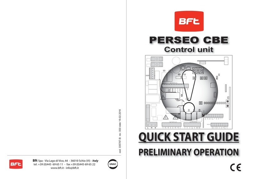
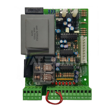
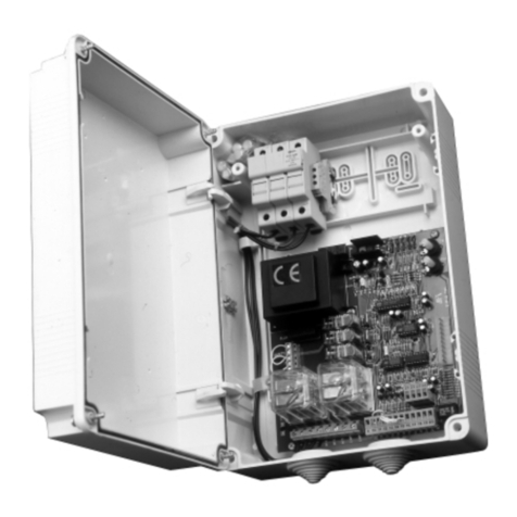
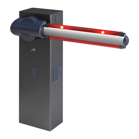
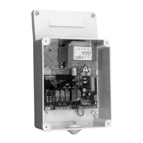
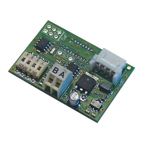
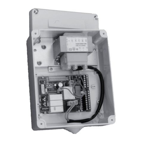
BFT RIGEL 5 User manual

ISTRUZIONI D’USO E DI INSTALLAZIONE
INSTALLATION AND USER’S MANUAL
INSTRUCTIONS D’UTILISATION ET D’INSTALLATION
INSTALLATIONS-UND GEBRAUCHSANLEITUNG
INSTRUCCIONES DE USO Y DE INSTALACION
INSTALLATIEVOORSCHRIFTEN
CENTRALINA UNIVERSALE PER IL CONTROLLO DI UNO O DUE MOTORI
UNIVERSAL CONTROL UNIT FOR OPERATING ONE OR TWO MOTORS
UNITE DE COMMANDE UNIVERSELLE POUR LE CONTROLE D’UN OU DEUX MOTEURS
UNIVERSALSTEUERUNG FÜR EINEN ODER ZWEI MOTOREN
CENTRAL UNIVERSAL PARA EL CONTROL DE UNO O DOS MOTORES
CENTRAL UNIVERSAL PARA O CONTROLO DE UM OU DOIS MOTORES
Attenzione! Leggere attentamente le“Avvertenze” all’interno! Caution! Read “Warnings” inside carefully! Attention! Veuillez lire attentivement les Avertissements qui se trouvent à l’intérieur! Achtung! Bitte lesen Sie
aufmerksam die„Hinweise“ im Inneren! ¡Atención¡ Leer atentamente las“Advertencias”en el interior! Let op! Lees de“Waarschuwingen”aan de binnenkant zorgvuldig!
RIGEL 5
RIGEL 5
D811472 00100_01 29-10-09

2 - RIGEL 5
D811472 00100_01

INSTALLAZIONE VELOCE-QUICK INSTALLATION-INSTALLATION RAPIDE
SCHNELLINSTALLATION-INSTALACIÓN RÁPIDA - SNELLE INSTALLATIE
ITALIANO ENGLISH FRANÇAIS DEUTSCH ESPAÑOL
NEDERLANDS
Display + tasti programmazione
Display + programming keys
Display + Programmierungstasten
Pantalla + botones programación
Display + programmeringstoetsen
N
L
1234567891011121314151617181920212223242526
31 32 33 34
JP2
JP3
24V
~
230V
~
F
G
M
NO
NO
FAULT
COM
PED
COM
NC
SWC
NC
SWO
24V
~
0V
ANT
Grigio-Grey-Gris-Grau-Gris-Grijs
A
B
C
D
E
SCA/2°CH
COM
NO
NC
NO
NC
NC
START
CLOSE
STOP
PHOT
BAR
OPEN
Connettore programmatore palmare,
Palmtop programmer connector,
Connecteur programmateur de poche,
Steckverbinder Palmtop-Programmierer,
Conector del programador de bolsillo,
Connectorprogrammeerbare palmtop
.
Connettore programmatore palmare,
Palmtop programmer connector,
Connecteur programmateur de poche,
Steckverbinder Palmtop-Programmierer,
Conector del programador de bolsillo,
Connectorprogrammeerbare palmtop.
T 0,62 A
T 1 A
Connettore scheda opzionale
Optional board connector
Connecteur carte facultative
Steckverbinder Zusatzkarte
Conector de la tarjeta opcional
Connector optionele kaart
Connettore ricevitore radio
Radio receiver connector
Connecteur Récepteur Radio
Stecker Funkempfänger
Conector del receptor de radio
Connector Radio-ontvanger
A
C
B
D
MEMORIZZAZIONE RADIOCOMANDO
MEMORIZING REMOTE CONTROLS
MÉMORISATION RADIOCOMMANDE
ABSPEICHERUNG DER FERNBEDIENUNG
MEMORIZACION DEL RADIOMANDO
GEHEUGENOPSLAG AFSTANDSBEDIENING
0"'-
x 2
x 2
OK
.P+
OK
OK
$GLC
#LB$GL
R?QRML?QAMQRMFGBBCL
@SRRML
RMSAFC
A?AFCCTCPQRR?QRC
PGJ?QAG?PCJC?QC
PCJ?AFC
JMQJ?QQCLQSCJRC
R?QRMBCQGBCP?RM
BCQGBCP@SRRMLRMSAFC
BCQGPCC
ECTSC
R?QRCRCAJ?BCQC?B?
EEQR?PRBHMSRCP
QR?PRXSDSCEQR?PR
?L?BQR?PR
+ x 3
+
OK
VSAFE ~(+)
VSAFE ~(-)
24V ~(+)
24V ~(-)
25W max.
315 mA/T 230V
630 mA/T 110V
6,3 A/F 230V
10 A/F 110V
Display + tasti programmazione
Display + programming keys
Display + Programmierungstasten
Pantalla + botones programación
Display + programmeringstoetsen
0,5A max
(2A 2 sec.)
12
220
320
125
Collegamento di 1 coppia di fotocellule non verificate, Connection of 1 pair of non-tested
photocells, Connexion 1 paire photocellules non vériées, Anschluss von einem Paar nicht
überprüften Fotozellen, Conexión de 1 par fotocélulas no comprobadas, Aansluiting van 1 paar
fotocellen anders dan “trusted device”
LOGICA test fotocellule OFF
Photocell test LOGIC OFF
LOGIQUE essai photocellules Désactivée
LOGIK Test Fotozellen OFF
LÓGICA prueba fotocélulas OFF
LOGICA test fotocellen OFF
SSR5 (Fig. F)
1
2
3
4
5
6
7
1
2
1
2
3
4
5
TX1 RX1
1-PHOT
20 21
JP3
24 V~
24 V~
33 34 35 36 37
JP4
COM
PHOT
COM
BAR
VSafe +
VSafe -
230V
150W
max.
230V
150W
max.
10 11 12 13 10 11 12 13
Dip *?NCEE = ON
Dip @JGLI = ON
Dip DCSAJGEL= ON
Dip @JGLI = ON
Dip JSXGLR= ON
Dip *?NCEE = OFF
Dip @JGLI = OFF
Dip DCSAJGEL= OFF
Dip @JGLI = OFF
Dip JSXGLR= OFF
RIGEL 5 - 3
D811472 00100_01

J?LE
RGNM
LMR
'2
DP?
BCS
CLE
CQN
CJCR
GBP
CJCR : operatore elettromeccanico
?P: funzionamento automatico,
residenziale
QP: funzionamento semi-automatico,
residenziale
?A: funzionamento automatico,
condominiale
1A: funzionamento semi-automatico,
condominiale
'LB: funzionamento a uomo presente
GBP : operatore idraulico
0
NPCQCR
C
R?QRML?QAMQRM
PGJ?QAG?
-
R?QRMBCQGBCP?RM
RCJCA
QP
?A
QA
GLB
DGLC
x1
D811690_beta test 07-04-09
MENU STANDARD
x2
-+
-+
-+
+/-
"#$3*2
OK OK
QR?R TCPQ
@DRPGECJ
DGLC
DGLC
+/-
DGLC
+/-
OK
+/-
+/-
L?L
OK
LRCJCAM
MENU IMPOSTAZIONE IMPIANTO
PRESET DEFAULT AR SR AC SC ind
PARAMETRI
Tempo Chiusura Automatica 40 20 40 30 40 40
Tempo di lavoro Motore 1 60 20 20 20 20 20
Tempo di lavoro Motore 2 60 20 20 20 20 20
Tempo di lavoro pedonale 6 6 6 6 6 6
Tempo di ritardo apertura anta 1 3 2 2 2 2 2
Tempo di ritardo chiusura anta 2 3 2 2 2 2 2
Tempo di
rallentamento
idraulico 00 0 0 0 0
elettromeccanico
3 3 3 3 3
Tempo di sgombero 15 15 15 15 15 15
Preriscaldamento 30 30 30 30 30 30
Coppia motori in
rallentamento
idraulico 40 99 99 99 99 99
elettromeccanico
50 50 50 50 50
Coppia motori idraulico 40 99 99 99 99 99
elettromeccanico
50 50 50 50 50
Frenatura 0 0 0 0 0 0
Frenatura di emergenza
60 60 60 60 60 60
Zona 0 0 0 0 0 0
LOGICHE
Chiusura Automatica OFF ON OFF ON OFF OFF
Blocca impulsi in apertura OFF OFF OFF ON ON OFF
Blocca impulsi in TCA OFF OFF OFF OFF OFF OFF
Blocca impulsi in chiusura OFF OFF OFF OFF OFF OFF
Colpo d’ariete in apertura OFF OFF OFF OFF OFF OFF
Colpo d’ariete in chiusura OFF OFF OFF OFF OFF OFF
Logica 2 passi OFF OFF OFF OFF OFF OFF
Logica 3 passi OFF ON OFF ON OFF OFF
Preallarme OFF OFF OFF ON ON OFF
Mantenimento blocco
idraulico OFF ON ON ON ON ON
elettromeccanico
OFF OFF OFF OFF OFF
Uomo presente OFF OFF OFF OFF OFF ON
Fotocellule in apertura OFF ON ON ON ON OFF
Chiusura rapida OFF OFF OFF OFF OFF OFF
Test fotocellule OFF OFF OFF OFF OFF OFF
Test costa OFF OFF OFF OFF OFF OFF
Test fotocellule apertura OFF OFF OFF OFF OFF OFF
Test fotocellule in chiusura OFF OFF OFF OFF OFF OFF
Master/slave OFF OFF OFF OFF OFF OFF
Codice sso OFF OFF OFF OFF OFF OFF
Programmazione via radio ON ON ON ON ON OFF
Conteggio tempi
idraulico OFF OFF OFF OFF OFF OFF
elettromeccanico
ON ON ON ON ON
Luce cortesia OFF OFF OFF OFF OFF OFF
Orologio/Pedonale OFF OFF OFF OFF OFF OFF
Luce/Allarme OFF OFF OFF OFF OFF OFF
1 motore attivo OFF ----- ----- ----- ----- -----
Sca/2ch OFF OFF OFF OFF OFF OFF
Bar ON ON ON ON ON ON
Uscita lampeggiante OFF OFF OFF OFF OFF OFF
Tipo serratura OFF OFF OFF OFF OFF OFF
4 - RIGEL 5
D811472 00100_01

x1
J?LES?EC
RWNC
LMR
'2
DP?
BCS
CLE
CQN
CJCA
FWBP
0
NPCQCR
CFGBBCL@SRRML
PCJC?QC -
PCMRCQ
QP
?A
QA
GLB
CLB
?P: automatic operation, residential
QP: semiautomatic operation, residential
?A: automatic operation, commercial
1A: semiautomatic operation, commercial
'LB: dead man operation
CJCA: electromechanical operator
FWBP: hydraulic operator
BCQGBCPCB@SRRML
Exit Menù
Confirm/Switch on display
Scroll up
Scroll down
SYSTEM SETTINGS MENU
PRESET DEFAULT AR SR AC SC ind
PARAMETER
Automatic closing time (TCA) 40 20 40 30 40 40
Operation time motor 1 60 20 20 20 20 20
Operation time motor 2 60 20 20 20 20 20
Pedestrian operation time 6 6 6 6 6 6
Opening delay time for leaf 1 3 2 2 2 2 2
Closing delay time for leaf 2 3 2 2 2 2 2
Slow-down time hydraulic 00 0 0 0 0
electromechanical
3 3 3 3 3
Trac-light area clearance time 15 15 15 15 15 15
Preheating 30 30 30 30 30 30
Slowdown motor
torque
hydraulic 40 99 99 99 99 99
electromechanical
50 50 50 50 50
Motor torque hydraulic 40 99 99 99 99 99
electromechanical
50 50 50 50 50
Braking 0 0 0 0 0 0
Emergency braking 60 60 60 60 60 60
Zona 0 0 0 0 0 0
LOGIC
Automatic Closing OFF ON OFF ON OFF OFF
Opening Impulse lock OFF OFF OFF ON ON OFF
Impulse lock TCA OFF OFF OFF OFF OFF OFF
Impulse lock on closing OFF OFF OFF OFF OFF OFF
Ram blow on opening OFF OFF OFF OFF OFF OFF
Ram blow in closing OFF OFF OFF OFF OFF OFF
2-step logic OFF OFF OFF OFF OFF OFF
3-step logic OFF ON OFF ON OFF OFF
Pre alarm OFF OFF OFF ON ON OFF
Lock hold hydraulic OFF ON ON ON ON ON
electromechanical
OFF OFF OFF OFF OFF
Hold-to-run OFF OFF OFF OFF OFF ON
Photocells on opening OFF ON ON ON ON OFF
Rapid closing OFF OFF OFF OFF OFF OFF
Photocell test OFF OFF OFF OFF OFF OFF
Electric edge test
OFF OFF OFF OFF OFF OFF
Photocell test on opening OFF OFF OFF OFF OFF OFF
Photocell test on closing OFF OFF OFF OFF OFF OFF
Master/Slave OFF OFF OFF OFF OFF OFF
Fixed code OFF OFF OFF OFF OFF OFF
Radio transmitter programming ON ON ON ON ON OFF
Time count hydraulic OFF OFF OFF OFF OFF OFF
electromechanical
ON ON ON ON ON
Courtesy light OFF OFF OFF OFF OFF OFF
Clock / Pedestrian OFF OFF OFF OFF OFF OFF
Light/Alarm OFF OFF OFF OFF OFF OFF
1 Active motor OFF ----- ----- ----- ----- -----
Gate-open or 2nd radio channel warning
light OFF OFF OFF OFF OFF OFF
Safety edge ON ON ON ON ON ON
Blinking output OFF OFF OFF OFF OFF OFF
Type of lock OFF OFF OFF OFF OFF OFF
RIGEL 5 - 5
D811472 00100_01

x1
J?LES?EC
RWNC
LKMR
'2
DP?
BCS
CLE
CQN
CJCA
FWBP
CJCA: operateur électromécanique
?P: fonctionnement automatique
QP: fonctionnement semi-automat.
?A: fonctionnement automatique,
collectif
1A: fonctionnement semi-automat.
'LB: fonctionnement à homme
présent
FWBP: operateur hydraulique
0
NPCQCR
C
RMSAFCA?AFCC
PCJ?AFCP
-RMSAFCBCQGPCC
RCJCA
QP
?A
QA
GLB
DGL
Sortir du menu
Confirmation/Allumage
afficheur
Monter
Descendre
MENU CONFIGURATION INSTALLATION
PRESET DEFAULT AR SR AC SC ind
PARAMÈTRES
Temps de fermeture automatique tca40 20 40 30 40 40
Temps de travail moteur 1 60 20 20 20 20 20
Temps de travail moteur 2 60 20 20 20 20 20
Temps de travail piétons 6 6 6 6 6 6
Temps de retard ouverture du vantail 1 3 2 2 2 2 2
Temps de retard fermeture du vantail 2 3 2 2 2 2 2
Temps de
ralentissement
hydraulique 00 0 0 0 0
electromecanique
3 3 3 3 3
Temps de dégagement de la zone du feu 15 15 15 15 15 15
Préchauage 30 30 30 30 30 30
Couples
moteurs en
ralentissement
hydraulique
40
99 99 99 99 99
electromecanique
50 50 50 50 50
Couple moteurs hydraulique 40 99 99 99 99 99
elettromeccanico
50 50 50 50 50
Freinage 0 0 0 0 0 0
Freinage d’urgence 60 60 60 60 60 60
Zone 0 0 0 0 0 0
LOGIQUES
Fermeture automatique OFF ON OFF ON OFF OFF
Blocage des Impulsions d’ouverture OFF OFF OFF ON ON OFF
Blocage des Impulsions TCA OFF OFF OFF OFF OFF OFF
Blocage des impulsions en
fermeture OFF OFF OFF OFF OFF OFF
Coup de bélier en overture OFF OFF OFF OFF OFF OFF
Coup de bélier en fermeture OFF OFF OFF OFF OFF OFF
Logique 2 pas OFF OFF OFF OFF OFF OFF
Logique 3 pas OFF ON OFF ON OFF OFF
Préalarme OFF OFF OFF ON ON OFF
Maintient du
blocage
hydraulique OFF ON ON ON ON ON
electromecanique
OFF OFF OFF OFF OFF
Action Maintenue OFF OFF OFF OFF OFF ON
Cellules photoélectriques en
ouverture OFF ON ON ON ON OFF
Fermeture rapide OFF OFF OFF OFF OFF OFF
Test cellules photoélectriques OFF OFF OFF OFF OFF OFF
Test barre palpeuse OFF OFF OFF OFF OFF OFF
Test cellules photoélectriques en ouverture
OFF OFF OFF OFF OFF OFF
Essai des cellules photoélectriques en
fermeture
OFF OFF OFF OFF OFF OFF
Maître/Esclave OFF OFF OFF OFF OFF OFF
Code Fixe OFF OFF OFF OFF OFF OFF
Programmation des radio commandes ON ON ON ON ON OFF
Comptage des
temps
hydraulique
OFF
OFF OFF OFF OFF OFF
electromecanique
ON ON ON ON ON
Lumière de courtoisie OFF OFF OFF OFF OFF OFF
Minuteur / Piétons OFF OFF OFF OFF OFF OFF
Lumière/Alarme OFF OFF OFF OFF OFF OFF
1 Moteur Actif OFF ----- ----- ----- ----- -----
Témoin de portail ouvert ou II canal radio OFF OFF OFF OFF OFF OFF
Barre palpeuse ON ON ON ON ON ON
Sortie clignotante OFF OFF OFF OFF OFF OFF
Type de serrure OFF OFF OFF OFF OFF OFF
6 - RIGEL 5
D811472 00100_01

x1
QNP?AFC
RWNC
LKMR
'2
DP?
BCS
CLE
CQN
CJCA
FWBP
CJCA: elektromechanischer
Bediener
?P: Automatikbetrieb,
Wohnbereich
QP: Halbautomatikbetrieb,
Wohnbereich
?A: Automatikbetrieb,
Hausbereich
1A: Halbautomatikbetrieb,
Hausbereich
'LB: Betrieb bei anwesendem
Menschen
FWBP: hydraulischer Bediener
0
NPCQCR
CTCPQRR?QRC
JMQJ?QQCL
-
ECTSCR?QRC
RCJCA
QP
?A
QA
GLB
#,"
Zurück zum Hauptmenü
Bestätigung/
Aufleuchten Display
Aufwärts
Abwärts
Legende:
MENU INSTELLING SYSTEEM
PRESET DEFAULT AR SR AC SC ind
PARAMETER
Zeit für Schließautomatik 40 20 40 30 40 40
Arbeitszeit für motor 1 60 20 20 20 20 20
Arbeitszeit für motor 2 60 20 20 20 20 20
Arbeitszeit Fußgängerfunktion 6 6 6 6 6 6
Verzögerungsdauer Önung Flügel 1 3 2 2 2 2 2
Verzögerungsdauer Schließung Flügel 2 3 2 2 2 2 2
Verlangsamungs-
dauer
hydraulischer 00 0 0 0 0
elektromechanischer 3 3 3 3 3
Räumungszeit Ampelbereich 15 15 15 15 15 15
Vorerwärmung 30 30 30 30 30 30
Drehmoment
bei Endlagedäm-
pfung
hydraulischer 40 99 99 99 99 99
elektromechanischer 50 50 50 50 50
Motordrehzahl hydraulischer 40 99 99 99 99 99
elektromechanischer 50 50 50 50 50
Bremsung 0 0 0 0 0 0
Notbremsung 60 60 60 60 60 60
Zone 0 0 0 0 0 0
LOGIC
Automatische Schließung OFF ON OFF ON OFF OFF
Impulssperre bei der Önung OFF OFF OFF ON ON OFF
Impulssperre TCA OFF OFF OFF OFF OFF OFF
Impulssperre bei der Schließung OFF OFF OFF OFF OFF OFF
Gegendrucksteuerung OFF OFF OFF OFF OFF OFF
Gegendrucksteueung beim Schließens OFF OFF OFF OFF OFF OFF
2-Schritt-, 4-Schrittlogik OFF OFF OFF OFF OFF OFF
3-Schritt-Logik OFF ON OFF ON OFF OFF
Voralarm OFF OFF OFF ON ON OFF
Aufrechterhalten
der Sperre
hydraulischer OFF ON ON ON ON ON
elektromechanischer OFF OFF OFF OFF OFF
Totmann-Funktion OFF OFF OFF OFF OFF ON
Fotozellen bei Önung OFF ON ON ON ON OFF
Schnellschließung OFF OFF OFF OFF OFF OFF
Test Lichtschranken
OFF OFF OFF OFF OFF OFF
Test Sicherheitsleiste
OFF OFF OFF OFF OFF OFF
Test Lichtschranken
OFF OFF OFF OFF OFF OFF
Test Fotozellen beim Schließen
OFF OFF OFF OFF OFF OFF
Master/Slave
OFF OFF OFF OFF OFF OFF
Festcode
OFF OFF OFF OFF OFF OFF
Fernbedienungsprogrammierung
ON ON ON ON ON OFF
Zeitzählwerk hydraulischer OFF OFF OFF OFF OFF OFF
elektromechanischer ON ON ON ON ON
Nachtbe leuchtung OFF OFF OFF OFF OFF OFF
Uhr / Fußgängerfunktion OFF OFF OFF OFF OFF OFF
Leuchte /Alarm OFF OFF OFF OFF OFF OFF
1 Motor aktiv OFF ----- ----- ----- ----- -----
Kontrollampe“Tor oen”oder 2. Funkkanal
OFF OFF OFF OFF OFF OFF
Sicherheitsleiste ON ON ON ON ON ON
Ausgang Blinkleuchte OFF OFF OFF OFF OFF OFF
Schloßtyp OFF OFF OFF OFF OFF OFF
RIGEL 5 - 7
D811472 00100_01

GBGMK?
RGNM
LMR
'2
DP?
BCS
CLE
CQN
CJCR
GBP
CJCR : operador electromecánico
?P: funcionamiento automático,
residencial
QP: funcionamiento semiautomático,
residencial
?A: funcionamiento automático, en
edicios
1A: funcionamiento semiautomático,
en edicios
'LB: funcionamiento con hombre
presente
GBP : operador hidráulico
0
NPCQCR
C
RCAJ?CQAMLB
QSCJRC
-
RCAJ?CQAMLB
RCJCA
QP
?A
QA
GLB
DGLC
x1
MENÚ DE CONFIGURACIÓN DE LA INSTALACIÓ
Retorno al menú
principal
Confirmación/
Encendido pantalla
Desplazar hacia arriba
Desplazar hacia abajo
PRESET DEFAULT AR SR AC SC ind
PARAMETROS
Tiempo de Cierre Automático 40 20 40 30 40 40
Tiempo de trabajo motor 1 60 20 20 20 20 20
Tiempo de trabajo motor 2 60 20 20 20 20 20
Tiempo de trabajo peatonal 6 6 6 6 6 6
Tiempo de retardo de apertura hoja 1 3 2 2 2 2 2
Tiempo de retardo de cierre hoja 2 3 2 2 2 2 2
Tiempo de decele-
ración
hidráulico 00 0 0 0 0
electromecánico
3 3 3 3 3
Tiempo de evacuación zona de semáforo 15 15 15 15 15 15
Precalentamiento 30 30 30 30 30 30
Par motores en de-
celeración
hidráulico 40 99 99 99 99 99
electromecánico
50 50 50 50 50
Par motores hidráulico 40 99 99 99 99 99
electromecánico
50 50 50 50 50
Frenado 0 0 0 0 0 0
Frenado de emergencia 60 60 60 60 60 60
Zona 0 0 0 0 0 0
LOGICA
Cierre Automático OFF ON OFF ON OFF OFF
Bloquea impulsos en fase de apertura OFF OFF OFF ON ON OFF
Bloquea Impulsos TCA OFF OFF OFF OFF OFF OFF
Bloquea impulsos en fase de cierre OFF OFF OFF OFF OFF OFF
Golpe de ariete en apertura OFF OFF OFF OFF OFF OFF
Golpe de ariete en fase de cierre OFF OFF OFF OFF OFF OFF
Lógica de 2 pasos, 4 pasos OFF OFF OFF OFF OFF OFF
Lógica de 3 pasos OFF ON OFF ON OFF OFF
Pre alarma OFF OFF OFF ON ON OFF
Mantenimientodel
bloqueo
hidráulico OFF ON ON ON ON ON
electromecánico
OFF OFF OFF OFF OFF
Hombre Presente OFF OFF OFF OFF OFF ON
Fotocélulas en fase de apertura OFF ON ON ON ON OFF
Cierre rápido OFF OFF OFF OFF OFF OFF
Test fotocélulas OFF OFF OFF OFF OFF OFF
Test barra sensible OFF OFF OFF OFF OFF OFF
Test para fotocélulas en fase de apertura OFF OFF OFF OFF OFF OFF
Test para fotocélulas en fase de cierre OFF OFF OFF OFF OFF OFF
Master/Slave OFF OFF OFF OFF OFF OFF
Código Fijo OFF OFF OFF OFF OFF OFF
Programación de los radiomandos ON ON ON ON ON OFF
Cálculo de los
tiempos
hidráulico OFF OFF OFF OFF OFF OFF
electromecánico
ON ON ON ON ON
Luz interior OFF OFF OFF OFF OFF OFF
Reloj / Peatonal OFF OFF OFF OFF OFF OFF
Luz/Alarma OFF OFF OFF OFF OFF OFF
1 Motor activado OFF ----- ----- ----- ----- -----
Luz de aviso de cancela abierta o II°
canal radio OFF OFF OFF OFF OFF OFF
Barra sensible ON ON ON ON ON ON
Salida luz intermitente OFF OFF OFF OFF OFF OFF
Tipo de cerradura OFF OFF OFF OFF OFF OFF
8 - RIGEL 5
D811472 00100_01

x1
J?LES?EC
RWNC
LMR
'2
DP?
BCS
CLE
CQN
CJCA
FWBP
0
NPCQCR
CFGBBCL@SRRML
PCJC?QC -
PCMRCQ
QP
?A
QA
GLB
CLB
?P: automatische werking,
residentieel
QP: semi-automatische werking,
residentieel
?A: automatische werking,
gemeenschappelijk
1A: semi-automatische werking,
gemeenschappelijk
'LB: werking bij aanwezige persoon
CJCA: elektromechanische
automatisering
FWBP: hydraulische automatisering
BCQGBCPCB@SRRML
VEREENVOUDIGD MENU
Terugkeer naar het
hoofdmenu
Bevestig/Aanschakeling
display
Doorloop op
Doorloop neer
LEGEND:
PRESET DEFAULT AR SR AC SC ind
PARAMETERS
Tijd Automatische Sluiting 40 20 40 30 40 40
Werktijd motor 1 60 20 20 20 20 20
Werktijd motor 2 60 20 20 20 20 20
Werktijd“voetganger” 6 6 6 6 6 6
Vertragingstijd opening vleugel 1 3 2 2 2 2 2
Vertragingstijd sluiting vleugel 2 3 2 2 2 2 2
Vertragingstijd hydraulische 00 0 0 0 0
elektromechanische
3 3 3 3 3
Ontruimingstijd verkeerslichtzone 15 15 15 15 15 15
Voorverwarming 30 30 30 30 30 30
Motorkoppel in
vertraging
hydraulische 40 99 99 99 99 99
elektromechanische
50 50 50 50 50
Motorkoppel hydraulische 40 99 99 99 99 99
elektromechanische
50 50 50 50 50
Afremming 0 0 0 0 0 0
Noodremming 60 60 60 60 60 60
Zone 0 0 0 0 0 0
LOGICA
Automatische Sluiting OFF ON OFF ON OFF OFF
Blokkeert impulsen bij opening OFF OFF OFF ON ON OFF
Blokkeert impulsen in TCA OFF OFF OFF OFF OFF OFF
Blokkeert impulsen bij sluiting OFF OFF OFF OFF OFF OFF
Leidingslag bij opening OFF OFF OFF OFF OFF OFF
Leidingslag bij sluiting OFF OFF OFF OFF OFF OFF
2-staps - 4-staps logica OFF OFF OFF OFF OFF OFF
3-staps logica OFF ON OFF ON OFF OFF
Pre-alarm OFF OFF OFF ON ON OFF
Handhaving blo-
kkering
hydraulische OFF ON ON ON ON ON
elektromechanische
OFF OFF OFF OFF OFF
Persoon Aanwezig OFF OFF OFF OFF OFF ON
Fotocellen bij opening OFF ON ON ON ON OFF
Snelle sluiting OFF OFF OFF OFF OFF OFF
Test fotocellen OFF OFF OFF OFF OFF OFF
Test gevoelige rand
OFF OFF OFF OFF OFF OFF
Test fotocellen bij opening OFF OFF OFF OFF OFF OFF
Test fotocellen bij sluiting OFF OFF OFF OFF OFF OFF
Master/Slave OFF OFF OFF OFF OFF OFF
Vaste Code OFF OFF OFF OFF OFF OFF
Programmering afstandsbedieningen ON ON ON ON ON OFF
Telling van de ti-
jden
hydraulische OFF OFF OFF OFF OFF OFF
elektromechanische
ON ON ON ON ON
Hulplicht OFF OFF OFF OFF OFF OFF
Klok / Voetgan OFF OFF OFF OFF OFF OFF
Licht/Alarm OFF OFF OFF OFF OFF OFF
1 Motor actief OFF ----- ----- ----- ----- -----
Verklikkerlichtsignaal open hek of IIe
radiokanaal OFF OFF OFF OFF OFF OFF
Gevoelige rand ON ON ON ON ON ON
Uitgang knipperlicht OFF OFF OFF OFF OFF OFF
Type slot OFF OFF OFF OFF OFF OFF
RIGEL 5 - 9
D811472 00100_01

TEST PHOT=OFF
D
1
2
1
2
3
4
5
20
21
20
21
20
21
33
35
TX1 RX1
1-PHOT
1
2
1
2
3
4
5
20
44
20
21
20
44
20
21
20
44
33
35
TX1 RX1
53
1-PHOT
1-BAR
Bar 1
1
2
3
4
5
6
21
20
33
37
1-BAR
Bar 1
1
2
3
4
5
6
21
20
33
54
37
44
2-BAR
3-BAR
4-BAR
1
2
1
2
3
4
5
33
35
TX1 RX1
2-PHOT
3-PHOT
4-PHOT
1
2
1
2
3
4
5
53
33
TX2 RX2
1
2
1
2
3
4
5
33
35
TX1 RX1
1
2
1
2
3
4
5
44
20
21
20
44
20
21
20
44
20
21
20
46
45
47
TX2 RX2
1
2
1
2
3
4
5
53
33
TX3 RX3
46
47
49
48
50
45
1
2
1
2
3
4
5
44
20
21
20
44
20
21
20
44
20
21
20
44
20
21
20
33
35
TX1 RX1
1
2
1
2
3
4
5
TX2 RX2
1
2
1
2
3
4
5
TX3 RX3
1
2
1
2
3
4
5
53
33
TX4 RX4
Bar 1
1
2
3
4
5
6
21
20
33
37
44
Bar 2
1
2
3
4
5
6
21
20
54
33
44
Bar 1
1
2
3
4
5
6
21
20
33
37
44
Bar 2
1
2
3
4
5
6
21
20
54
33
46
45
44
Bar 3
1
2
3
4
5
6
21
20
54
33
44
47
Bar 1
1
2
3
4
5
6
21
20
33
37
44
Bar 2
1
2
3
4
5
6
21
20
44
Bar 4
1
2
3
4
5
6
21
20
54
33
44
Bar 3
1
2
3
4
5
6
21
20
49
47
50
48
44
TEST BAR = ON
FAULT/PHOT= OFF
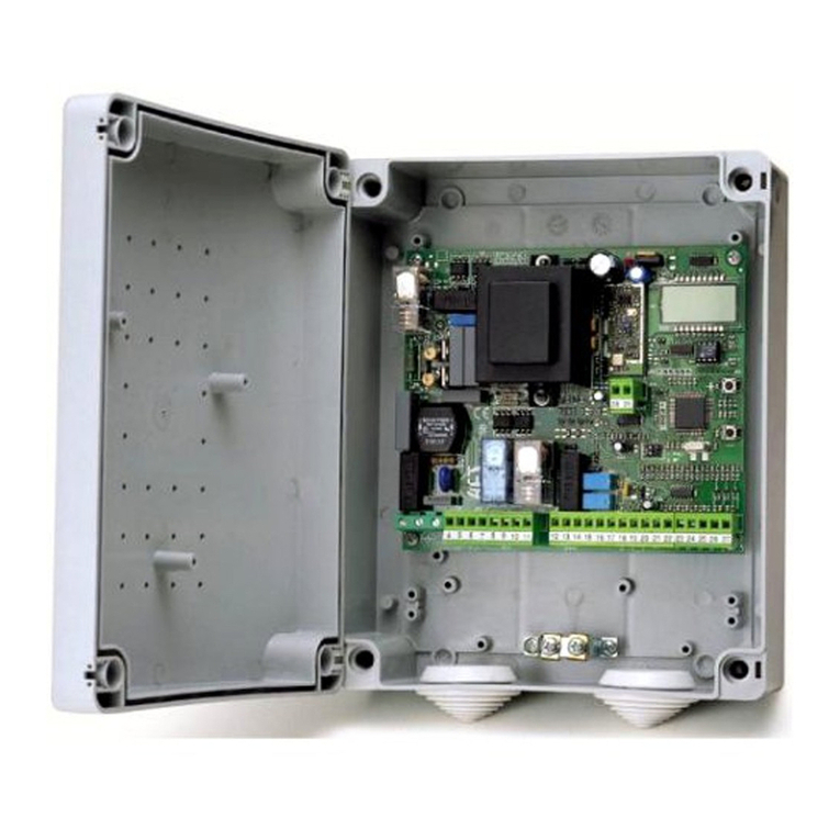
FAULT/PHOT= ON
FAULT/PHOT=ON FAULT/PHOT=OFF
TEST PHOT=OFF
Combinazioni possibili, Possible combinations, Combinaisons possibiles, Mögliche Kombinationen, Combinaciones posibles, Mogelijke combinaties
TEST PHOT = ON
TEST BAR=OFF
TEST BAR = ON
TEST PHOT CLOSE=OFF
TEST PHOT CLOSE = ON
12 B
B
B
B
3
4
5
A
C
D
E
1
1
1
1
2
1
2
3
4
5
21
20
21
20
33
55
TX1 RX1
1-PHOT
1
2
1
2
3
4
5
44
20
21
20
33
55
TX1 RX1
56
1-PHOT
1
2
1
2
3
4
5
44
20
21
20
33
55
TX1 RX1
2-PHOT
3-PHOT
4-PHOT
1
2
1
2
3
4
5
44
20
21
20
56
33
TX2 RX2
1
2
1
2
3
4
5
44
20
21
20
33
55
TX1 RX1
1
2
1
2
3
4
5
44
20
21
20
46
45
47
TX2 RX2
1
2
1
2
3
4
5
44
20
21
20
56
53
TX3 RX3
46
47
49
48
50
45
1
2
1
2
3
4
5
44
20
21
20
33
55
TX1 RX1
1
2
1
2
3
4
5
44
20
21
20
TX2 RX2
1
2
1
2
3
4
5
44
20
21
20
TX3 RX3
1
2
1
2
3
4
5
44
20
21
20
56
33
TX4 RX4
C1
C3
C4
C5
A1
A4
A5
B1
FOTOCELLULE
FOTOZELLEN
PHOTOCELLS
FOTOCÉLULAS
PHOTOCELLULES
FOTOCELLEN
COSTE
LEISTEN
SAFETY EDGES
CANTOS
LINTEAUX
RANDEN
FAULT/PHOT= ONFAULT/PHOT= OFF
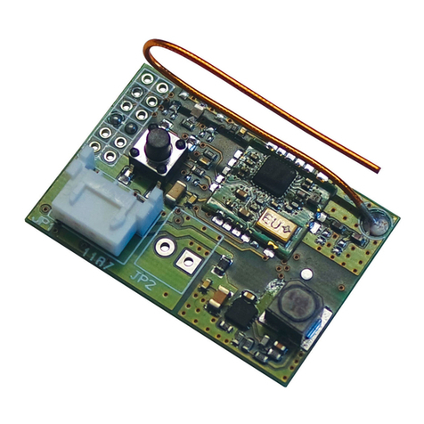
FOTOCELLULE
FOTOZELLEN
PHOTOCELLS
FOTOCÉLULAS
PHOTOCELLULES
FOTOCELLEN
COSTE
LEISTEN
SAFETY EDGES
CANTOS
LINTEAUX
RANDEN
FOTOCELLULE, PHOTOCELLS, PHOTOCELLULES,
FOTOZELLEN, FOTOCÉLULAS, FOTOCELLEN
FOTOCELLULE IN CHIUSURA, PHOTOCELLS, PHOTO-
CELLULES, FOTOZELLEN, FOTOCÉLULAS, FOTOCEL-
LEN
20 21
JP3
24 V~
24 V~
33 34 35 36 37
JP4
COM
PHOT
COM
BAR
52 53 54 55 56
JP6
COM
24 VTX
FLT PHOT
FLT BAR
PHOT CL
FLT CL
44 45 46 47 48 49 50
JP5
A2
A3
B2
B3
B4
B5
C2
PERFIS
КРОМКИ ΑΝΙΧΝΕΥΤΕΣ ΕΜΠΟΔΙΩΝ
BEZPEČNOSTNÍ LIŠTY LISTWY
GÜVENLİK KENARLARI PERFIS
КРОМКИ ΑΝΙΧΝΕΥΤΕΣ ΕΜΠΟΔΙΩΝ
BEZPEČNOSTNÍ LIŠTY LISTWY
GÜVENLİK KENARLARI
COSTE / FOTOCELLULE IN APERTURA, COSTE /
FOTOCELLULE IN APERTURA, COSTE / FOTOCEL-
LULE IN APERTURA, COSTE / FOTOCELLULE IN
APERTURA, COSTE / FOTOCELLULE IN APERTURA,
COSTE / FOTOCELLULE IN APERTURA.
10 - RIGEL 5
D811472 00100_01

F
E
F
D1
SCS1 SCS1 SCS1
Max. 250m
TX1
TX2
RX1
RX2
TX1
TX2
RX1
RX2
TX1
TX2
RX1
RX2
Semaforo 1 esterno
Outside traffic light 1
Feu 1 extérieur
Ampel 1 Aussen
Semáforo 1exterior
Semáforo 1 externo
Semaforo 2 interno
Inside traffic light 2
Feu 2 intérieur
Ampel 2 Innen
Semáforo 2 interior
Semáforo 2 interno
R1 R2
G1 G2
DIP function
1 Blinking
2 Red light in close position
6
7
1
2
3
4
5
6
7
Combinazioni non possibili, Not possible combinations, Combinaisons non possibiles, Nicht mogliche kombinationen,
Combinaciones no posibles, Combinaties niet mogelijk.
Programmeerbare Universele Palmtop
UNIDA
Fotocellule, Photocells,
Photocellules, Fotozellen,
Fotocellulas, Fotocellen.
Coste / Fotocellule in Apertura, Coste / Fotocellule in Apertura, Coste /
Fotocellule in Apertura, Coste / Fotocellule in Apertura, Coste / Fotocel-
lule in Apertura, Coste / Fotocellule in Apertura,
Fotocellule in Chiusura, Fotocellule in Chiusura, Fo-
tocellule in Chiusura, Fotocellule in Chiusura, Foto-
cellule in Chiusura, Fotocellule in Chiusura.
A1 B4 C5
A1 B5 C4, C5
A2 B4 C5
A2 B5 C4, C5
A3 B4 C5
A3 B5 C4, C5
A4 B1 C5
A4 B2 C5
A4 B3 C5
A4 B4 C4, C5
A4 B5 C1, C2, C3, C4, C5
A5 B1 C4, C5
A5 B2 C4, C5
A5 B3 C4, C5
A5 B4 C1, C2, C3, C4, C5
A5 B5 C1, C2, C3, C4, C5
RIGEL 5 - 11
D811472 00100_01

ACCESSO AI MENU Fig. 1
DGLC
QR?R
x 2
-+
-+
OK
OK
QR?R
TCPQ
@DRPGECJ
+/-
DGLC
+/-
OK
+/-
+/-
L?L
OK
LRCJCAM
DIAGNOSTICA e SEGNALAZIONI
CODICE
DIAGNOSTICA DESCRIZIONE NOTE
stre attivazione ingresso START ESTERNO
stri attivazione ingresso START INTERNO
ped attivazione ingresso PEDONALE
open attivazione ingresso OPEN
cls attivazione ingresso CLOSE
stop attivazione ingresso STOP
phot attivazione ingresso FOTOCELLULA
phop attivazione ingresso FOTOCELLULA IN APERTURA
phcl attivazione ingresso FOTOCELLULA IN CHIUSURA
bar attivazione ingresso COSTA SENSIBILE
svc1 attivazione ingresso FINECORSA CHIUSURA MOTORE 1
svo1 attivazione ingresso FINECORSA APERTURA MOTORE 1
svc2 attivazione ingresso FINECORSA CHIUSURA MOTORE 2
svo2 attivazione ingresso FINECORSA APERTURA MOTORE 2
ti eattivazione ingresso TIMER
er01 anomalia test fotocellule vericare collegamento fotocellule
e/o impostazione parametri/logiche
er02 anomalia test coste vericare collegamento coste e/o
impostazione parametri/logiche
er03 anomalia test fotocellule apertura vericare collegamento fotocellule
e/o impostazione parametri/logiche
er04 anomalia test fotocellule chiusura vericare collegamento fotocellule
e/o impostazione parametri/logiche
Er1X * anomalia hardware vericare collegamenti al motore
* X= 0,1,…,9,A,B,C,D,E,F
12 - RIGEL 5
D811472 00100_01

AVVERTENZE GENERALI
ATTENZIONE Importanti istruzioni di sicurezza. Leggere e seguire attenta-
mente l’opuscolo Avvertenze ed il Libretto istruzioni che accompagnano il
prodotto poiché una installazione errata può causare danni a persone, ani-
mali o cose. Esse forniscono importanti indicazioni riguardanti la sicurezza,
l’installazione, l’uso e la manutenzione. Conservare le istruzioni per allegarle
al fascicolo tecnico e per consultazioni future.
1) SICUREZZA GENERALE
ATTENZIONE!Unainstallazioneerrataounusoimproprio delprodotto,
può creare danni a persone, animali o cose.
- Gli elementi costruttivi della macchina e l’installazione devono essere in
accordo con le seguenti Direttive Europee: 2004/108/CEE, 2006/95/CEE
e loro modiche successive. Per tutti i Paesi extra CEE, oltre alle norme
nazionali vigenti, per un buon livello di sicurezza è opportuno rispettare
anche le norme citate.
- La Ditta declina qualsiasi responsabilità derivante da un uso improprio
o diverso da quello per cui è destinato ed indicato nella presente do-
cumentazione nonché dall’inosservanza della Buona Tecnica nella co-
struzione delle chiusure (porte, cancelli, ecc.) e dalle deformazioni che
potrebbero vericarsi durante l’uso.
- Vericare che l’intervallo di temperatura dichiarato sia compatibile con il
luogo destinato all’installazione dell’automazione.
- Non installare il prodotto in atmosfera esplosiva.
- Togliere l’alimentazione elettrica, prima di qualsiasi intervento sull’im-
pianto. Scollegare anche eventuali batterie tampone se presenti.
- Prevedere sulla rete di alimentazione dell’automazione, un interruttore
o un magnetotermico onnipolare con distanza di apertura dei contatti
uguale o superiore a 3,5 mm.
- Vericare che a monte della rete di alimentazione, vi sia un interruttore
dierenziale con soglia da 0.03A.
- Vericare se l’impianto di terra è realizzato correttamente: collegare tutte
le parti metalliche della chiusura (porte, cancelli, ecc.) e tutti i componen-
ti dell’impianto provvisti di morsetto di terra.
- L’installazione deve essere fatta utilizzando dispositivi di sicurezza e co-
mandi conformi alla EN 12978.
- Applicare tutti i dispositivi di sicurezza (fotocellule, coste sensibili, ecc.)
necessari a proteggere l’area da pericoli di schiacciamento, convoglia-
mento, cesoiamento.
- Usare esclusivamente parti originali per qualsiasi manutenzione o ripa-
razione. La Ditta declina ogni responsabilità ai ni della sicurezza e del
buon funzionamento dell’automazione se vengono impiegati compo-
nenti di altri produttori.
- Non eseguire alcuna modica ai componenti dell’automazione se non
espressamente autorizzata dalla Ditta.
- Smaltire i materiali di imballo (plastica, cartone, polistirolo, ecc.) secondo
quanto previsto dalle norme vigenti. Non lasciare buste di nylon e poli-
stirolo alla portata dei bambini.
- Tutto quello che non è espressamente previsto in queste istruzioni, non
è permesso.
- L’apparecchio non è destinato a essere usato da persone (bambini com-
presi) le cui capacità siche, sensoriali e mentali siano ridotte, oppure in
mancanza di esperienza o di conoscenza, a meno che esse abbiano potu-
to beneciare, attraverso l’intermediazione di una persona responsabile
della loro sicurezza, di una sorveglianza o di istruzioni riguardanti l’uso.
Attenzione! Per il collegamento alla rete, utilizzare cavo multipolare di
sezioneminima3x1.5mm2edeltipoprevistodalle normativevigenti.A
titolodi esempio,seilcavoè all’esterno(all’aperto),deveessere almeno
pari a H07RN-F mentre, se all’interno (in canaletta), deve essere almeno
pari a H05 VV-F con sezione 3x1.5mm2.
Prevedere un interruttore onnipolare con apertura contatti di almeno
3 mm provvisto di protezione contro i sovraccarichi, atto a sezionare
l’automazione dalla rete.
Utilizzare esclusivamente pulsanti con portata non inferiore a 10A-
250V.
I conduttori devono essere vincolati da un ssaggio supplementare in
prossimità dei morsetti per esempio mediante fascette.
Aggiungere inoltre delle ulteriori fascette ai conduttori dei necorsa,
ai conduttori del primario e del secondario del trasformatore e ai con-
duttori collegati al circuito stampato.
Il cavo di alimentazione, durante l’installazione, deve essere sguai-
nato in modo da permettere il collegamento del conduttore di terra
all’appropriato morsetto lasciando però i conduttori attivi il più corti
possibile. Il conduttore di terra deve essere l’ultimo a tendersi in caso
di allentamento del dispositivo di ssaggio del cavo.
ATTENZIONE:iconduttoriabassissimatensionedisicurezzadevono
essere sicamente separati dai conduttori a bassa tensione.
L’accessibilità al vano elettrico e dei necorsa deve essere eseguita
esclusivamente da personale qualicato.
Deve essere garantito il rispetto delle norme di sicurezza vigenti per quanto
riguarda le persone, animali e cose, e in particolare devono essere evitati
rischi di infortuni dovuti a schiacciamento. Tutti i punti critici dovranno
essere protetti da dispositivi di sicurezza secondo quanto prevedono
le normative vigenti.
Una errata impostazione della sensibilità può creare danni a per-
sone, animali o cose.
VERIFICA DELL’AUTOMAZIONE
Prima di rendere denitivamente operativa l’automazione, controllare scru-
polosamente quanto segue:
• Vericare che tutti i componenti siano ssati saldamente.
• Controllare il corretto funzionamento di tutti i dispositivi di sicurezza
(fotocellule, coste sensibili ecc.)
• Vericare il sistema di antischiacciamento arresti il sistema entro i limiti
previsti dalle norme vigenti.
• Vericare il comando della manovra di emergenza.
• Vericare l’operazione di apertura e chiusura con i dispositivi di comando
applicati.
• Vericare la logica elettronica di funzionamento normale e personalizza-
ta.
MANUTENZIONE
- Ogni due anni, smontare il motoriduttore e sostituire il grasso lubricante.
- Per qualsiasi anomalia di funzionamento riscontrata, e non risolta, togliere
l’alimentazione di rete e richiedere l’intervento di personale qualicato
(installatore).
DEMOLIZIONE
L’eliminazione dei materiali va fatta rispettando le norme vigenti. Nel caso
di demolizione dell’automazione non esistono particolari pericoli o rischi
derivanti dall’automazione stessa. È opportuno, in caso di recupero dei
materiali, che vengano separati per tipologia (parti elettriche - rame - allu-
minio - plastica - ecc.).
SMANTELLAMENTO
Nel caso l’automazione venga smontata per essere poi rimontata in altro
sito bisogna:
- Togliere l’alimentazione e scollegare tutto l’impianto elettrico.
- Togliere l’attuatore dalla base di ssaggio.
- Smontare tutti i componenti dell’installazione.
- Nel caso alcuni componenti non possano essere rimossi o risultino dan-
neggiati, provvedere alla loro sostituzione.
Il buon funzionamento dell’automazione è garantito solo se
vengono rispettate i dati riportati in questo manuale. La Ditta
non risponde dei danni causati dall’inosservanza delle norme di
installazione e delle indicazioni riportate in questo manuale.
Le descrizioni e le illustrazioni del presente manuale non sono
impegnative.Lasciandoinalteratelecaratteristicheessenzialidel
prodotto, la Ditta si riserva di apportare in qualunque momento
le modiche che essa ritiene convenienti per migliorare tecnica-
mente, costruttivamente e commercialmente il prodotto, senza
impegnarsi ad aggiornare la presente pubblicazione.
ITALIANO
RIGEL 5 - 13
D811472 00100_01

MANUALE PER L’INSTALLAZIONE
1) GENERALITÀ
La centralina RIGEL 5 viene fornita dal costruttore con settaggio standard.
Qualsiasi variazione, deve essere impostata mediante il programmatore
palmare universale o display integrato. La Centralina supporta completa-
mente il protocollo EELINK.
Le caratteristiche principali sono:
- Controllo di uno o due motori no a 600W di potenza.
- Regolazione elettronica della coppia.
- Frenatura elettrodinamica regolabile.
- Rallentamento della velocità all’accostamento.
- Ingressi di ne-corsa chiusura / apertura separati per ogni motore.
- Uscita per luce di zona.
- Ingressi separati per le sicurezze.
- Uscita 12V per elettroserratura a scatto o a ventosa.
- Uscita per pilotare un timer.
- Ingresso orologio.
- Connettore per scheda semaforo / preriscaldamento motori.
- Ricevitore radio incorporato
La scheda è dotata di una morsettiera di tipo estraibile per rendere più
agevole la manutenzione o sostituzione. Viene fornita con una serie di ponti
precablati per facilitare l’installatore in opera.
I ponti riguardano i morsetti: 33-34, 35-36, 36-37, 38-39, 39-40, 41-42, 42-
43, 52-55. Se i morsetti sopraindicati, vengono utilizzati, togliere i rispettivi
ponti.
2) DATI TECNICI
CENTRALE
Alimentazione 230V ±10% 50Hz (*)
Isolamento rete/bassa tensione > 2MOhm 500V
Rigidità dielettrica rete/bt 3750V~ per 1 minuto
Corrente uscita motore 1A+1A max (230V~) - 2A+2A
max (110V~)
Corrente di commutazione relè motore 10A
Luce di zona/cortesia max 150W
Alimentazione accessori 24V~ (1A assorbimento max)
Elettroserratura 12V (0.5A max, 2A per 3 s)
Uscita luce/allarme a contatto n.o.
libero
max 3A 250V~
Spia cancello aperto 24V~ 3W max
Lampeggiante 230V 40W max
Fusibili Vedi Fig. A
Dimensioni Vedi Fig. B
RICEVITORE INTEGRATO
Associazione Comandi 1°ch. = start
2° ch. = relè 2°ch. per 1 sec.
Radioricevente Rolling-Code incorpo-
rata
frequenza 433.92MHz
N.° combinazioni 4 miliardi
N.°max.radiocomandi memorizzabili 63
Impedenza Antenna 50 Ohm (RG58)
(*) Tensioni speciali di alimentazione a richiesta.
Versioni trasmettitori utilizzabili:
TuttiitrasmettitoriROLLINGCODEcompatibilicon
3) PREDISPOSIZIONE TUBI
Predisporre l’impianto elettrico facendo riferimento alle norme vigenti per
gli impianti elettrici CEI 64-8, IEC364, armonizzazione HD384 ed altre norme
nazionali.
----------------------------------------------------------
4) COLLEGAMENTO MORSETTIERA FIG. A
Passati gli adeguati cavi elettrici nelle canalette e ssati i vari componenti
dell’automazione nei punti prescelti, si passa al loro collegamento secondo
le indicazioni e gli schemi riportati nei relativi manuali istruzione. Eettuare
la connessione della fase, del neutro e della terra (obbligatoria). Il cavo di
retevabloccato nell’appositopressacavo,icavi degliaccessori nell’apposito
pressacavo, il conduttore di protezione (terra) con guaina isolante di colore
giallo/verde, deve essere collegato nell’apposito serralo.
MORSETTO
DESCRIZIONE
1Morsetto GND
2-3 Alimentazione 230V~±10%, 50-60Hz (2 neutro, 3 fase).
4-5-6 Collegamentomotore1(ritardatoapertura),morsetti5-6marcia
motore, morsetto 4 comune.
5-14 Collegamento condensatore motore 1
7-8-9
Collegamentomotore2(ritardatochiusura),morsetti8-9marcia
motore, morsetto 7 comune.
N.B. Se si utilizza un solo motore utilizzare l’uscita per il motore
2 e congurare la logica“1 motore attivo”.
8-15 Collegamento condensatore motore 2.
10-11
Uscita 230V~ per luce lampeggiante (40W max) ed elettroser-
ratura modello EBP 230V.
ATTENZIONE!SesiusalaschedaausiliariaSSR5perpreriscalda-
mento motori, spostare il collegamento ai morsetti 12-13 (Fig.
A) e fare riferimento a Tabella “B”, Uscita lampeggiante.
12-13
Uscita 230V~ per luce di zona (dip luce cortesia ON, dip uscita
lampeggiante OFF)
Uscita 230V~ per luce di cortesia (dip luce cortesia OFF, dip
uscita lampeggiante OFF)
Uscita 230V~ per uscita lampeggiante (dip uscita lampeggiante
ON)
16-17
UscitaLuceScale(N.O.)(dipluce/allarme=OFF).Collegarequesti
morsettisoloa circuitiinbassissimatensionedisicurezza(SELV)
adeguatamente isolati da parti in tensione.
Uscita Allarme Cancello Aperto (N.O.) (dip luce/ allar-
me = ON). Collegare questi morsetti solo a cir-
cuiti in bassissima tensione di sicurezza (SELV)
adeguatamente isolati da parti in tensione.
18-19
Uscita N.O. per 2° canale radio (dip SCA - 2ch = OFF)
Uscita N.O. per luce spia di segnalazione cancello aperto.
Questa spia è spenta a cancello chiuso, lampeggia in chiusura
e rimane accesa con cancello aperto o in fase di apertura. (dip
SCA - 2ch = ON)
20-21 Uscita 24V~ (1A max) per alimentazione accessori.
20-44 Uscita 24V~ per alimentazione VSAFE
22-23
Uscita per elettroserratura 12V a scatto (dip tipo serratura
= OFF)
Uscita per elettroserratura 12V a ventosa (dip tipo serratura
= ON)
24-25 Ingresso antenna scheda radioricevente (24 segnale, 25 calza).
26-27 Pulsante START INTERNO (N.O.). Start interno per semaforo.
27-28 Pulsante START (N.O.). In parallelo al relè ricevente radio (CH1).
Start esterno per semaforo.
27-29 Pulsante PEDONALE (N.O.). L’azionamento avviene sul motore
2, inoltre, se il ciclo di apertura è iniziato (non da pedonale), il
comando pedonale ha lo stesso eetto di uno Start.
30-31 Pulsante APRE (N.O.).
30-32 Pulsante CHIUDE (N.O.).
33-34 Pulsante di BLOCCO (N.C.). Se non si utilizza lasciare il ponti-
cello inserito.
35-36 Ingresso contatto fotocellula PHOT (N.C.). Se non si utilizza
lasciare i ponticelli inseriti.
36-37
Ingresso contatto fotocellula PHOT APERTURA (N.C.). Se non si
utilizza lasciare i ponticelli inseriti. (dip BAR = OFF)
IngressocostaBAR(N.C.).Incasodiinterventodurantel’apertura
si ha l’arresto e la chiusura parziale. Se non si utilizza lasciare i
ponticelli inseriti. (dip BAR = ON)
38-39 Finecorsa apertura motore 1 SWO1 (N.C.). Se non si utilizza
lasciare il ponticello inserito.
39-40 Finecorsa chiusura motore 1 SWC1 (N.C.). Se non si utilizza
lasciare il ponticello inserito.
41-42 Finecorsa apertura motore 2 SWO2 (N.C.). Se non si utilizza
lasciare il ponticello inserito.
42-43 Finecorsa chiusura motore 2 SWC2 (N.C.). Se non si utilizza
lasciare il ponticello inserito.
45-46-47
Connessione dispositivi di sicurezza vericati (vedi Fig. D).
48-49-50
Connessione dispositivi di sicurezza vericati (vedi Fig. D).
14 - RIGEL 5
D811472 00100_01

MANUALE PER L’INSTALLAZIONE
51-52
IngressoOrologio(n.o.).Seilcontattocollegatoèaperto(n.o.),le
antesichiudonoesipredispongonoalnormalefunzionamento.
Se il contatto è chiuso (n.c.), le ante si aprono e rimangono
aperte no all’apertura del contatto. Se il movimento di aper-
tura comandato dal TIMER è inibito dalle sicurezze, il cancello
riprenderà l’apertura a fronte di un comando di START/OPEN.
52-55 Ingressi contatto fotocellula-costa di chiusura SAFE CL (n.c.).
In caso di intervento in chiusura si ha l’arresto e la riapertura
parziale. Se non si utilizza lasciare i ponticelli inseriti.
53 Ingresso verica fotocellula (PHOT-FAULT)
54 Ingresso verifica costa sensibile/fotocellule in apertura (BAR-FAULT)
56 Ingresso verica fotocellule in chiusura (PHOT CL-FAULT).
JP7 Connettore scheda radioricevente.
JP8 Connettore scheda opzionale (SCS)
JP9 Connettore scheda SSR5 Semaforo / Preriscaldamento.
5) COLLEGAMENTO CON SCHEDE DI ESPANSIONE E PROGRAMMATORE
PALMARE UNIVERSALE (Fig. A)
Fare riferimento al manuale specico.
6) DISPOSITIVI DI SICUREZZA
Nota:utilizzaresolamentedispositividisicurezzariceventiconcontatto
in libero scambio.
6.1) DISPOSITIVI VERIFICATI (Fig. D)
6.2) DISPOSITIVI NON VERIFICATI (Fig. C - D)
7 ACCESSO AI MENU: FIG. 1
7.1) MENU PARAMETRI PARA TABELLA “A” PARAMETRI
7.2) MENU LOGICHE LOGICTABELLA“B”LOGICHE
7.3) MENU RADIO radio TABELLA “C” RADIO
- NOTA IMPORTANTE: CONTRASSEGNARE IL PRIMO TRASMETTITORE
MEMORIZZATO CON IL BOLLINO CHIAVE (MASTER).
Il primo trasmettitore, nel caso di programmazione manuale, assegna il CO-
DICE CHIAVE DELLA RICEVENTE; questo codice risulta necessario per poter
eettuare la successiva clonazione dei radiotrasmettitori.
Lariceventedi bordoincorporatoClonixdispone inoltredi alcuneimportanti
funzionalità avanzate:
• Clonazione del trasmettitore master (rolling-code o codice sso).
• Clonazione per sostituzione di trasmettitori già inseriti nella ricevente.
• Gestione database trasmettitori.
• Gestione comunità di ricevitori.
Per l’utilizzo di queste funzionalità avanzate fate riferimento alle istruzioni
del programmatore palmare universale ed alla Guida generale program-
mazioni riceventi.
7.4 MENU LINGUA lingua
Consente di impostare la lingua del programmatore a display.
7.5 MENU DEFAULT default
Riporta la centrale ai valori preimpostati dei DEFAULT.
8) MODULI OPZIONALI SCS
8.1) CONNESSIONE SERIALE MEDIANTE SCHEDA SCS1 (Fig. A - E)
Il quadro di comando RIGEL 5 consente, tramite appositi ingressi e uscite
seriali (SCS1), la connessione centralizzata di più automazioni. In questo
modo è possibile, con un unico comando, eseguire l’apertura o la chiusura
di tutte le automazioni connesse.
Seguendo lo schema di Fig. E, procedere alla connessione di tutti i quadri co-
mando RIGEL 5, utilizzando esclusivamente un doppino di tipo telefonico.
Nel caso si utilizzi un cavo telefonico con più coppie risulta indispensabile
utilizzare i li della stessa coppia.
Lalunghezzadelcavotelefonicofraunaapparecchiaturaelasuccessiva
non deve eccedere i 250 m.
A questo punto è necessario congurare opportunamente ogni quadro
comando RIGEL 5, impostando inanzitutto una centrale MASTER, che avrà il
controllo di tutte le altre, necessariamente settate come SLAVE (vedi menu
logiche).
Impostare inoltre il numero di Zona (vedi menu parametri) tra 0 e 127.
Ilnumerodi zonaconsentedi crearedei gruppi diautomazioni,ognuna delle
quali risponde al Master di Zona. Ogni zona può avere un solo Master, il
Master della zona 0 controlla anche gli Slave delle altre zone.
8.2) INTERFACCIA CON SISTEMI WIEGAND TRAMITE MODULO SCS-WIE.
Fare riferimento alle istruzioni del modulo SCS-WIE
9) SCHEDA SEMAFORO / PRERISCALDAMENTO MOTORI SSR5
Inserita nel connettore predisposto, consente:
- Gestione di due semafori a 2 luci.
- Preriscaldamento motori per clima freddo.
Fare riferimento al manuale specico.
9.1) Predisposizione semaforo
Il semaforo 1 deve essere posto all’esterno del cancello ed il semaforo 2
all’interno.
AVVERTENZE - Predisporre segnali che limitino la velocità “A passo
d’uomo”.
9.2) Predisposizione preriscaldamento motori (SSR5)
La sonda“S”deve essere posta e ssata all’esterno per rilevare la temperatura
esterna.Vacollegataai rispettivi morsetti7-8dellascheda preriscaldamento.
AVVERTENZE - Spostare Lampeggiante e elettroserratura EBP su 12-13.
(Fig. A Rif. 2).
AVVERTENZE - Impostare dip lampeggiante = ON.
RIGEL 5 - 15
D811472 00100_01

MANUALE PER L’INSTALLAZIONE
10.1 TABELLA A: MENU PARAMETRI PARA
Parametro min. max. default personali Denizione Descrizione
TCA 3 sec. 120 sec. 40 Tempo Chiusura Automatica Imposta il tempo di chiusura automatica da 3 a 120 secondi.
t.lavoro
ot1 3 sec. 180 sec. 60 Tempo di lavoro motore 1 Imposta il valore del tempo di lavoro da 3 a 180 secondi per il motore 1.
t.lavoro
ot 2 3 sec. 180 sec. 60 Tempo di lavoro motore 2 Imposta il valore del tempo di lavoro da 3 a 180 secondi per il motore 2.
t.pedonale 3 sec. 9 sec. 6 Tempo di lavoro pedonale Imposta il valore del tempo di apertura pedonale del motore 2 da 3 a 90 secondi.
t.sfas.ap 0 sec. 10 sec. 3 Tempo di ritardo apertura
anta 1 Impostailtempodiritardodiaperturadelmotore1rispettoalmotore2,regolabile
da 0 secondi a 10 secondi.
t.sfas.ch 0 sec. 60 sec. 3 Tempo di ritardo chiusura
anta 2 Imposta il tempo di ritardo di chiusura del motore 2, regolabile da 0 a 60 se-
condi.
t.rall 0 sec. 20 sec. 0 Tempo di rallentamento
Imposta il tempo di rallentamento all’accostamento, da 0 a 20 secondi. Il tempo di
rallentamento viene sottratto al tempo di lavoro.
NOTA: si consiglia di attivare il conteggio dei tempi.
NOTA: Usare questa funzione solo in presenza di necorsa.
NOTA: Non usare con motori idraulici.
t.sgo b. 0 sec. 30 sec. 15 Tempo di sgombero zona
semaforica
Imposta il tempo desiderato di sgombero della zona interessata dal traco regolato dal
semaforo, da 0 a 30 secondi. Impostare a 0 se non utilizzato.
prerisc. 0% 99% 30% Preriscaldamento
Imposta il valore percentuale di corrente da 0 (preriscaldamento disattivato)
a 99% che si può far passare negli avvolgimenti dei motori per mantenerli in
temperatura.
NOTA: Solo con SSR5.
coppia
rall. 1% 99% 50% Coppia motori in rallen-
tamento Imposta il valore da 1 a 99% della coppia motori durante il rallentamento.
coppia ot 1% 99% 50% Coppia motori Imposta il valore da 1 a 99% della coppia motori.
freno 0% 99% 0% Frenatura Imposta il valore di frenatura da 0% (min.) a 99% (max.) compatibilmente con il
peso del cancello e con le sollecitazioni meccaniche presenti.
freno
eer. 0% 99% 60% Frenatura di emergenza Imposta il valore da 0% (min.) a 99% (max.) della frenatura di emergenza, che
viene eseguita attivando i comandi di sicurezza presenti agli ingressi 34 (Blocco),
37 (SAFE OP), 55 (SAFE CL).
Zone 0 127 0 Zona Imposta il numero di zona tra 0 e 127. Vedi paragrafo“Moduli opzionali SCS”.
10.2 TABELLA B: MENU LOGICHE logic
Logica Default Denizione
Barrare il
settaggio
eseguito Descrizione
TCA OFF Tempo Chiusu-
ra Automatica
ON Attiva la chiusura automatica
OFF Esclude la chiusura automatica.
bl.i p.
ap OFF Blocca impulsi
in apertura
ON L’impulso di start non ha alcun eetto durante la fase di apertura.
OFF L’impulso di start ha eetto durante la fase di apertura.
bl.i p.
tca OFF Blocca impulsi
in TCA
ON L’impulso si start non ha eetto durante la pausa TCA.
OFF Accetta lo start durante la pausa TCA.
bl.i p.
ch OFF Blocca impulsi
in chiusura
ON L’impulso di start non ha alcun eetto durante la fase di chiusura.
OFF L’impulso di start ha eetto durante la fase di chiusura.
col.
ariete
ap.
OFF Colpo di ariete
in apertura
ON
Prima di eettuare l’apertura il cancello spinge per circa 2 secondi in chiusura. Questo consente lo sgancio più
agevole della elettroserratura (non è inuenzato dai ne-corsa).
IMPORTANTE - In assenza di adeguati fermi d’arresto meccanici, non usare questa funzione. E’ assolutamente
vietata nella motorizzazione di cancelli scorrevoli.
OFF Esclude il colpo d’ariete.
col.
ariete
ch.
OFF Colpo di ariete
in chiusura
ON
Prima di eettuare la chiusura il cancello spinge per circa 2 secondi in apertura. Questo consente lo sgancio più
agevoledellaelettroserratura(nonèinuenzatodaine-corsa).IMPORTANTE-Inassenzadiadeguatifermid’arresto
meccanici, non usare questa funzione. E’assolutamente vietata nella motorizzazione di cancelli scorrevoli.
OFF Esclude il colpo d’ariete.
2 passi OFF Logica 2 passi -
4 passi
ON Abilita la logica 2 passi ( prevale su “Logica 3 passi ” ). Risposta all’impulso di START:
2 passi 3 passi 4 passi
chiusa apre apre apre
in chiusura stop
aperta chiude chiude chiude
in apertura stop + TCA stop + TCA
dopo stop apre apre apre
OFF Abilita la logica 4 passi (nel caso in cui la Logica 3 passi
sia impostata a OFF).
3 passi OFF Logica 3 passi ON Abilita la logica 3 passi (con logica 2 passi = OFF).
OFF Disabilita la Logica a 3 passi.
preAll. OFF Pre allarme ON Il lampeggiante si accende circa 3 secondi prima della partenza del motore.
OFF Il lampeggiante si accende contemporaneamente alla partenza dei motori.
ant.
blocco OFF Mantenimento
blocco
ON
Se i motori rimangono fermi in posizione di completa apertura o completa chiusura per più di un’ora, vengono
attivati per circa 3 secondi nella direzione di battuta. Tale operazione viene eettuata ogni ora.
N.B.:Questa funzionehalo scopodicompensare,nei motori oleodinamicil’eventuale riduzionedivolume dell’olio
dovuta alla diminuzione della temperatura durante le pause prolungate, ad esempio durante la notte, o dovute
a tralamenti interni.
IMPORTANTE - In assenza di adeguati fermi d’arresto meccanici, non usare questa funzione. E’ assolutamente
vietata nella motorizzazione di cancelli scorrevoli.
OFF Esclude Mantenimento Blocco.
uo o
pres OFF Uomo Presente ON Funzionamentoauomo presente:lamanovra continuanchèvienemantenuta la pressionesul tasto di comando.
IMPORTANTE - Non è possibile utilizzare il radiocomando.
OFF Funzionamento a impulsi
16 - RIGEL 5
D811472 00100_01

MANUALE PER L’INSTALLAZIONE
Fotoc.
ap. OFF Fotocellule in
apertura
ON In caso di oscuramento, esclude il funzionamento della fotocellula in apertura. In fase di chiusura, inverte im-
mediatamente.
OFF In caso di oscuramento, le fotocellule sono attive sia in apertura che in chiusura. Un oscuramento della fotocellula
in chiusura, inverte il moto solo dopo il disimpegno della fotocellula.
ch.
rapida OFF Chiusura rapi-
da
ON Chiude il cancello dopo il disimpegno delle fotocellule prima di attendere il termine del TCA impostato.
OFF Comando non inserito
test
phot OFF Test fotocellule ON Attiva la verica delle fotocellule (vedi Fig. D)
OFF Disattiva la verica delle fotocellule
test BAR OFF Test costa sen-
sibile
ON Attiva la verica delle coste sensibili (vedi Fig. D)
OFF Disattiva la verica coste sensibili.
test phot
op. OFF Test fotocellule
in apertura
ON Abilita la verica delle fotocellule attive in apertura (vedi Fig. D).
OFF Disabilita la verica delle fotocellule attive in apertura.
test phot
cl. OFF Test fotocellule
in chiusura
ON Abilita la verica delle fotocellule attive in chiusura (vedi Fig. D).
OFF Disabilita la verica delle fotocellule attive in chiusura
aster OFF Master/Slave ON Il quadro comando viene settato come Master in un collegamento centralizzato (vedi Par.“Moduli Opzionali SCS”).
OFF Il quadro comando viene settato come Slave in un collegamento centralizzato (vedi Par. “Moduli Opzionali SCS”).
cod.
fisso OFF Codice Fisso ON Il ricevitore risulta congurato per il funzionamento in modalità codice sso.
OFF Il ricevitore risulta congurato per il funzionamento in modalità rolling-code.
prog.
radio ON
Programma-
zione radioco-
mandi
ON
Abilita la memorizzazione via radio dei trasmettitori:
1- Premere in sequenza il tasto nascosto (P1) e il tasto normale (T1-T2-T3-T4) di un trasmettitore già memorizzato
in modalità standard attraverso il menu radio.
2- Premere entro 10s il tasto nascosto (P1) ed il tasto normale (T1-T2-T3-T4) di un trasmettitore da memorizzare.
La ricevente esce dalla modalità programmazione dopo 10s, entro questo tempo è possibile inserire ulteriori
nuovi trasmettitori.
Questa modalità non richiede l’accesso al quadro comando.
OFF
Disabilita la memorizzazione via radio dei trasmettitori.
I trasmettitori vengono memorizzati solo utilizzando l’apposito menu Radio.
Non vengono accettati Cloni o Replay.
cont.
te pi OFF Conteggio dei
tempi
ON La centralina calcola il tempo di attivazione di ogni motore in base alle manovre precedenti.
OFF La centralina attiva i Motori ad ogni manovra per il tempo impostato.N.B. In ogni caso impostare il tempo di lavoro
ad un valore leggermente superiore a quello necessario per compiere la manovra completa.
l. zona OFF Luce cortesia
ON Luce di zona. Rimane attivo per tutta la durata della manovra.
OFF Luce di cortesia. Rimane attivo per 90 secondi dopo l’ultima manovra.
N.B. Queste impostazioni non sono utilizzabili se l’uscita lampeggiante è impostata su ON.
orol. ped OFF Orologio / Pe-
donale
ON
Ingresso per il collegamento di un temporizzatore esterno.
L’ingresso Orologio agisce solo nel Motore 2, per il tempo pedonale impostato. Uno start dato durante la fase orologio,
esegue l’apertura e chiusura completa del cancello, ripristinando la posizione di pedonale aperto.
OFF L’ingresso Orologio agisce su entrambi i motori.
allar e
- luce
ON
Luce/Allarme ON
Uscita allarme cancello aperto ( si attiva se il cancello rimane aperto per un tempo doppio rispetto al TCA impostato)
OFF
Comando luce scale (l’impulso rimane per 1 secondo)
1 ot.
att. OFF 1 Motore atti-
vo
ON Attivo solo motore 2 (1 anta).
OFF Attivi entrambi i motori (2 ante).
sca-2ch OFF
Spia cancello
aperto o II° ca-
nale radio
ON L’uscita tra i morsetti 18-19 viene congurata come Spia cancello aperto, il II° canale radio in questo caso comanda
l’apertura pedonale.
OFF L’uscita tra i morsetti 18-19 viene congurata come II° canale radio
bar ON Costa sensibile ON L’ingresso morsetti 36-37 è attivo come ingresso costa sensibile.
OFF L’ingresso morsetti 36-37 è attivo come ingresso fotocellule in apertura.
la pegg. OFF Uscita lampeg-
giante
ON
Attivare questa funzione solo in presenza della scheda semaforo-preriscaldo SSR5.
Imposta l’uscita ai morsetti 12-13 (“luce di cortesia”) come uscita lampeggiante (attiva solo durante la movimen-
tazione delle ante).
N.B. Qualsiasi impostazione relativa alla funzione“luce di cortesia”viene ignorata.
OFF
Mantiene l’uscita ai morsetti 12-13 come“luce di cortesia”o “luce di zona”.
ATTENZIONE! Non è possibile utilizzare la scheda SSR5 in modalità preriscaldo motori ed allo stesso tempo avere
Luce di zona/Luce di cortesia e Lampeggiante/Elettroserratura. Le uscite 10-11 in questo caso non possono essere
utilizzate e le uscite 12-13 possono essere utilizzate solamente per una delle due funzioni.
s.
ventosa OFF Tipo serratura ON Serratura a ventosa. Attivata con cancello chiuso.
OFF Serratura a scatto. Attivata con un impulso ad ogni apertura.
10.3 TABELLA C: MENU RADIO RADIO
Logica Descrizione
Agg start Aggiungi Tasto start
associa il tasto desiderato al comando Start
Agg 2ch Aggiungi Tasto 2ch
associa il tasto desiderato al comando 2° canale radio
eli . 64 Elimina Lista
ATTENZIONE! Rimuove completamente dalla memoria della ricevente tutti i radiocomandi memorizzati.
Lettura codice ricevente
Visualizza il codice ricevente necessario per la clonazione dei radiocomandi.
ON = Abilita la programmazione a distanza delle schede tramite un trasmettitore W LINK precedentemente memorizzato.
Questa abilitazione rimane attiva 3 minuti dall’ultima pressione del radiocomando W LINK.
OFF= Programmazione W LINK disabilitata.
RIGEL 5 - 17
D811472 00100_01

N?P?K
N?P?K
N?P?K
JMEGAJMEGA
JMEGA
JMEGA
.0%
'2
$0
"#3
#,%
CQN
OK
OK
OK
OK
OK
-+
-+
-+
-+
?BBQR?PR
FGBBCL@SRRML
PCJC?QC MI
BCQGPCB@SRRML
.0%
CP?QC
!-"06
!
OK
$"
OK
OK
BBAF
+/-
See PARAMETERS MENU
See LOGIC MENU
P?BGM
ACCESS TO MENUS Fig. 1
CLB
CLB
CLB
CLB
CLB
CLB
J?LES?EC
BCD?SJR
MI
FGBBCL@SRRML
PCJC?QC BCQGPCB@SRRML
T
Exit Menù
Confirm/Switch on display
Scroll up
Scroll down
x 2
-+
-+
OK OK
QR?R TCPQ
@DRPGECJ
+/-
OK
+/-
+/-
LAWAJCQ
OK
L0CKMRCQ
DIAGNOSTICS and WARNINGS
DIAGNOSTICS
CODE DESCRIPTION NOTES
stre EXTERNAL START input activation
stri INTERNAL START input activation
ped input activation PEDESTRIAN
open OPEN input activation
cls CLOSE input activation
stop STOP input activation
phot PHOT input activation
phop activation of input for PHOTOCELL ON OPENING
phcl activation of input for PHOTOCELL ON CLOSING
bar input activation SAFETY EDGE
svc1 activation of input for MOTOR 1 CLOSING LIMIT
SWITCH
svo1 activation of input for MOTOR 1 OPENING
LIMIT SWITCH
svc2 activation of input for MOTOR 2 CLOSING LIMIT
SWITCH
svo2 activation of input for MOTOR 2 OPENING
LIMIT SWITCH
ti eTIMER input activation
Er01 photocell test anomaly check photocell connection and/or
parameter/logic settings
Er02 safety edge test anomaly check safety edge connection and/or
parameter/logic settings
er03 photocell on opening test anomaly check photocell connection and/or
parameter/logic settings
er04 photocell on closing test anomaly check photocell connection and/or
parameter/logic settings
Er1X * hardware anomaly check connections to motor
* X= 0,1,…,9,A,B,C,D,E,F
18 - RIGEL 5
D811472 00100_01

ENGLISH
WARNING! Important safety instructions. Carefully read and comply with
the Warnings booklet and Instruction booklet that come with the product as
incorrect installation can cause injury to people and animals and damage to
property. They contain important information regarding safety, installation,
use and maintenance. Keep hold of instructions so that you can attach them
to the technical le and keep them handy for future reference.
1) GENERAL SAFETY
WARNING! An incorrect installation or improper use of the product can
cause damage to persons, animals or things.
- The units making up the machine and its installation must meet the
requirementsofthefollowingEuropeanDirectives:2004/108/EEC,2006/95/
EECandlateramendments.Forallcountries outsidetheEEC,itis advisable
tocomplywiththeabove-mentionedstandards,inadditiontoanynational
standards in force, to achieve a good level of safety.
- The Firm disclaims all responsibility resulting from improper use or any
use other than that for which the product has been designed, as indica-
ted herein, as well as for failure to apply Good Practice in the construc-
tion of entry systems (doors, gates, etc.) and for deformation that could
occur during use.
- Make sure the stated temperature range is compatible with the site in
which the automated system is due to be installed.
- Do not install the product in an explosive atmosphere.
- Disconnect the electricity supply before performing any work on the sy-
stem. Also disconnect buer batteries, if any are connected.
- Have the automated system’s mains power supply tted with a switch or
omnipolar thermal-magnetic circuit breaker with a contact separation of
at least 3.5 mm.
- Make sure that upline from the mains power supply there is a residual
current circuit breaker that trips at 0.03A.
- Make sure the earth system has been installed correctly: earth all the me-
tal parts belonging to the entry system (doors, gates, etc.) and all parts of
the system featuring an earth terminal.
- Installation must be carried out using safety devices and controls that
meet standard EN 12978.
- Apply all safety devices (photocells, safety edges, etc.) required to keep
the area free of crushing, dragging and shearing hazards.
- Only use original spare parts for any maintenance or repair work. The
Firm disclaims all responsibility for the correct operation and safety of
the automated system if parts from other manufacturers are used.
- Do not make any modications to the automated system’s components
unless explicitly authorized by the Firm.
- Dispose of packaging materials (plastic, cardboard, polystyrene, etc.) in
accordance with the provisions of the laws in force. Keep nylon bags and
polystyrene out of reach of children.
- Anything which is not expressly provided for in the present instructions,
is not allowed.
- The device is not meant to be used by people (including children) whose
physical, sensory or mental capacities are impaired or who do not have
suitable experience or knowledge, unless a person responsible for their
safety provides them with supervision or operating instructions.
Warning! For connection to the mains power supply, use a multicore
cable with a cross-section of at least 4x1.5mm2of the kind provided for
bytheregulationsmentioned above(byway of example,typeH05VV-F
cablecanbeusedwithacross-sectionof4x1.5mm2).Toconnectauxiliary
equipment, use wires with a cross-section of at least 0,75 mm2.
Have an omnipolar circuit breaker installed with a contact separation
of at least 3 mm and featuring overload protection, suitable for cutting
the automated device o from the mains.
Only use pushbuttons with a capacity of 10A-250V or more.
The cables must be held in position using an extra xing device in the
proximity of the terminals, e.g. with cable clamps.
Alsoaddmoreclips to the limitdevicewires, tothetransformerprimary
or secondary wires, and to the wires connected to the printed circuit.
During installation, the power supply cable must be stripped in order
for the earthing wire to be connected to the appropriate terminal, but
the active wires must be left as short as possible. The earthing wire
must be the last to stretch in the case where the cable xing device
becomes loose.
WARNING: extremely low safety voltage cables must be phisically
separatedfromlowvoltagecables.Accesstotheelectricalcompart-
ment or to limit switches must be allowed to skilled personnel only.
Settingsensitivityincorrectlycanresultindamagetopropertyand
injury to people and animals.
Compliance with current safety rules with regard to people, animals and
property must be assured at all times and, more specically, measures must
be taken to avoid risks of injury due to crushing, in the area where the pinion
and rack mesh, and any other mechanical hazards. All critical points must
be protected by safety devices in accordance with the provisions of the
regulations in force.
CHECKING THE AUTOMATED DEVICE
Before the automated device is nally put into operation, perform the fol-
lowing checks meticulously:
• Make sure all components are fastened securely.
• Check the correct functioning of all safety devices (limit microswitches,
photocells, sensitive edges etc.).
• Make sure that the anti-crush system stops the door within the limits
provided for by the standards in force.
• Check the emergency operation control device.
•
Check the opening and closing operations with the control devices in use.
• Check the standard and customised electronic functioning logic.
MAINTENANCE
- Dismantle the gearmotor and replace the lubricating grease every two
years.
- When any operational malfunction is found, and not resolved, discon-
nect the mains power supply and request the assistance of a specialised
technician (installer).
SCRAPPING
Materials must be disposed of in conformity with the current regulations.
In case of scrapping, the automation devices do not entail any particular
risks or danger. In case of recovered materials, these should be sorted out
by type (electrical components, copper, aluminium, plastic etc.).
DISMANTLING
Whentheautomation system isdisassembledtobe reassembled onanother
site, proceed as follows:
- Disconnect the power supply and the entire electrical installation.
- Remove the actuator from its xing base.
- Disassemble all the installation components.
- In the case where some of the components cannot be removed or are
damaged, they must be replaced.
GENERAL WARNINGS
Correctcontrolleroperationisonlyensuredwhenthedatacontainedin
thepresent manualareobserved.TheCompanyisnotto beheldrespon-
sible for any damage resulting from failure to observe the installation
standards and the instructions contained in the present manual.
The descriptions and illustrations contained in the present manual are
not binding. The Company reserves the right to make any alterations
deemed appropriate for the technical, manufacturing and commercial
improvement of the product, while leaving the essential product fea-
tures unchanged, at any time and without undertaking to update the
present publication.
RIGEL 5 - 19
D811472 00100_01

INSTALLATION MANUAL
1) FOREWORD
The RIGEL 5 control unit is supplied by the manufacturer with standard
setting. Any modications must be entered using the universal palmtop
programmer or the incorporated display. This Control unit supports the
entire EELINK protocol.
These are its main features:
- Control of one or two motors up to 600W power.
- Electronic torque setting.
- Adjustable electrodynamic braking.
- End-of-run speed slow-down.
- Separate opening / closing limit-switch inputs for each motor.
- Output for zone light.
- Separate inputs for safety devices.
- 12V output for click or suction-type electric lock.
- Output for timer piloting.
- Clock input.
- Connector for trac-light board / motor preheating.
- Incorporated radio receiver.
Theboardisprovidedwitharemovableterminalboardforeasiermaintenance
and replacement.This is supplied with a series of prewired jumpers to make
work easy for the installer.
The jumpers relate to the following terminals: 33-34, 35-36, 36-37, 38-39,
39-40, 41-42, 42-43, 52-55. If the above terminals are used, remove the
respective jumpers.
2) TECHNICAL SPECIFICATIONS
CONTROL UNIT
Power supply 230V±10% 50Hz*
Mains/low voltage insulation > 2MOhm 500V
Dielectric strength mains/bty 3750V~ for 1 minute
Motor output current 1A+1A max (230V~) - 2A+2A max
(110V~)
Motor relay commutation current 10A
Zone/courtesy light max 150W
Supply to accessories 24V~ (1A max absorption)
Electric lock 12V (0.5A max, 2A for 3 s)
Light/alarm output with free n.o.
contact
max 3A 250V~
Gate-open warning light 24V~ 3W max
Blinker 230V 40W max
Fuses See Fig. A
Dimensions See Fig. B
RECEIVER
Commands association 1st ch. = start
2nd ch. = relay 2nd ch. for 1 sec.
Built-in Rolling-Code radio-re-
ceiver
frequency 433.92MHz
N° of combinations 4 billion
Max. n° of remotes that can be
memorized
63
Antenna impedance 50 Ohm (RG58)
(*) Special supply voltages to order.
Usable transmitter versions:
AllROLLINGCODEtransmitterscompatiblewith
3) TUBE ARRANGEMENT Fig.A
Install the electrical system referring to the standards in force for electrical
systems CEI 64-8, IEC 364, harmonization document HD 384 and other
national standards.
----------------------------------------------------------
4) TERMINAL BOARD WIRING Fig. A
Once suitable electric cables have been run through the raceways and the
automated device’s various components have been fastened at the prede-
termined points, the next step is to connect them as directed and illustrated
in the diagrams contained in the relevant instruction manuals. Connect the
live, neutral and earth wire (compulsory). The mains cable must be clamped
intherelevantcablegland, andtheaccessories’wiresin thecablegland,while
the earth wire with the yellow/green-coloured sheath must be connected
in the relevant terminal.
TERMINAL
DESCRIPTION
1GND terminal
2-3 230V~±10%, 50-60Hz power supply (2 neutral, 3 phase).
4-5-6 Motorconnection1 (delayedopening),terminals5-6 formotor
drive, terminal 4 common.
5-14 Motor capacitor connection 1
7-8-9
Motor connection 2 (delayed closing), terminals 8-9 for motor
drive, terminal 7 common.
N.B.Ifonly onemotorisused,usemotoroutput2andcongure
logic“1 active motor”.
8-15 Motor capacitor connection 2.
10-11
230V~ output for blinker light (40W max) and EBP 230V mo-
delelectric lock. WARNING! If the SSR5 auxiliary board is used
for motor preheating, move the connection to terminals 12-13
(Fig. A) and refer to LOGIC TABLE“B”(Blinker output).
12-13
230V~ output for zone lighting (courtesy light dipswitch ON,
ashing light output dipswitch OFF)
230V~ output for courtesy light (courtesy light dipswitch OFF,
ashing light output dipswitch OFF)
230V~output forashing lightoutput (ashinglightdipswitch
ON)
16-17
Stair-light output (N.O.) (dip Light/alarm = OFF) Only connect
theseterminalstosafetyextralowvoltage(SELV)circuitssuitably
insulated from live parts.
Light/alarmoutput(N.O.)(dipLight/alarm =ON).Onlyconnect
theseterminalstosafetyextralowvoltage(SELV)circuitssuitably
insulated from live parts.
18-19
N.O. output for 2nd radio channel (SCA dipswitch - 2ch =
OFF)
N.O. output for gate open warning light.This warning light is o
when the gate is closed, ashes as it is closing and remains on
when the gate is open or opening. (dipswitch SCA - 2ch = ON)
20-21 24V~ output (1A max.) to power accessories.
20-44 24V~ output to power VSAFE
22-23 12V solenoid latch output (lock type dipswitch = OFF)
12V solenoid sucker output (lock type dipswitch = ON)
24-25 Antenna input for radio receiver board (24 signal, 25 braid).
26-27 INTERNAL START Pushbutton (N.O.). Internal Start command
for trac light.
27-28 START Pushbutton (N.O.). Parallel to radio receiver relay (CH1).
External Start command for trac light.
27-29
PEDESTRIAN pushbutton (N.O.). Activation takes place on
motor 2; moreover, if the opening cycle has started (not from
pedestrian pushbutton), the pedestrian control has the same
eect as a Start command.
30-31 OPEN Pushbutton (N.O.).
30-32 CLOSE Pushbutton (N.O.).
33-34 LOCK pushbutton (N.C.). If not used, leave the jumper con-
nected.
35-36 Photocell contact input PHOT (n.c.). If not used, leave jumpers
inserted.
36-37
PhotocellcontactinputPHOTOPENING(N.C.).Ifnot used,leave
jumpers inserted. (dipswitch BAR = OFF)
BAR safety edge input (n.c.) If intervenes during opening, it
stops and we have partial closure. If not used, leave jumpers
inserted. (dipswitch BAR = ON)
38-39 Openinglimitswitchformotor 1 SWO1 (N.C.). If not used, leave
the jumper connected.
39-40 Closing limit switch for motor 1 SWC1 (n.c.). If not used, leave
the jumper connected.
41-42 Opening limit switch for motor 2 SWO2 (n.c.). If not used, leave
the jumper connected.
42-43 Closing limit switch for motor 2 SWC2 (n.c.). If not used, leave
the jumper connected.
20-44 24V output for transmitters.
45-46-47 Connection with tested safety devices (see Fig. D)
48-49-50 Connection with tested safety devices (see Fig. D)
20 - RIGEL 5
D811472 00100_01
Other manuals for RIGEL 5
5
Table of contents
Languages:
Other BFT Control Unit manuals
Popular Control Unit manuals by other brands

National Instruments
National Instruments NI PXIe-7975R Getting started guide

GEM
GEM 649 eSyDrive operating instructions

MoreSense
MoreSense MSWB2213 user manual

VAT
VAT 612 Series Installation, operating, & maintenance instructions

GEM
GEM 533 operating instructions

thomann
thomann Harley Benton PA-100 user manual