BFT FR95 Series User manual

FR95
D811170 11-01-99 Vers. 03
AUTOMATION
FOR INDUSTRIAL
SECTIONAL DOORS

320
FR95
FR95
AUTOMATION FOR INDUSTRIAL SECTIONAL DOORS
D811170_03
We declare that this product is in conformity with the following European
Directives:
89/336/EEC (amended by RL 91/263/CEE, 92/31/CEE and
93/68/EEC),73/23/CEE (amended by RL 93/68/CEE).
1) GENERAL OUTLINE
This controller has been designed to motorize residential and industrial sec-
tional doors.
The compactness and versatility of the installation allow the motor drive to be
fitted in a variety of ways.
The controller is available in the following versions:
FR95-C Version with possibility of manual chain-opening and
closing.
FR95-CM Version with possibility of manual chain-opening and
closing and release mechanism for maintenance (the
release mechanism disengages the drive from the
cable winder shaft of the door).
FR95-SB Version with quick release for fast manual opening and
closing. The door should be perfectly balanced.
Safety microswitches protect each manual manoeuvre command.
The motor is supplied with an electro-mechanical brake to make the gear-
motor irreversible.
2) TECHNICAL SPECIFICATIONS
VOLTAGE Single-phase 230V ±5% 50Hz
Three-phase 400V ±5% 50Hz
ABSORPTION Single-phase 1.7 A
Three-phase 0.8 A
POWER Single-phase 0.25 Kw (Hp = 0.33)
Three-phase 0.33 Kw (Hp = 0.45)
MOTOR 1400 RPM (revs./min)
CAPACITOR 12.5 µF+16 µF (starting)
BRAKE Mechanical
INSULATION CLASS F
THERMAL PROTECTION 130°C self-resetting
REDUCTION GEAR OIL AGIP ALER 68
REDUCTION GEAR RATIO 1/43
OUTPUT REVS. 33 RPM
THROUGH-SHAFT 1” (Ø. 25.4 mm)
SPEED 8m/min with Z=18 1/2” x 5/16” (fig.4)
MAX DOOR WEIGHT Single-phase 350 daN (Kg)=25 m
2
Three-phase 700 daN (Kg)= 40 m
2
TORQUE PROVIDED Single-phase 5 daN (Kgm)
Three-phase 6 daN (Kgm)
IMPACT REACTION Stop and reverse (with pressure
sensitive edge)
DRIVE Link chain or direct drive
LIMITING DEVICES Built-in limit switches
CONTROL UNIT Mizar (single-phase)
Sirio TN1 (single-three-phase)
MANUAL MANOEUVRE With chain for FR-C/CM
Rapid for FR95-SB (FR95-CM)
NUMBER OF MANOEUVRES 100 Manoeuvres/24h
WORKING TEMPERATURE -15 + 60° C
PROTECTION IP 55
CONTROLLER WEIGHT 9 Kg
DIMENSIONS See fig. 1
3) INSTALLATION OF AUTOMATION
Preliminary checks
Check the balancing of the door.
Check that the door slides along the whole of its stroke.
Check the safety devices (parachute-type, cables etc.).
If a new door is not being installed, check whether the door and its compo-
nents are worn.
Repair or replace any worn or damaged parts.
Automation reliability and safety are directly influenced by the condition of the
sectional door’s structure.
4) CONTROLLER INSTALLATION
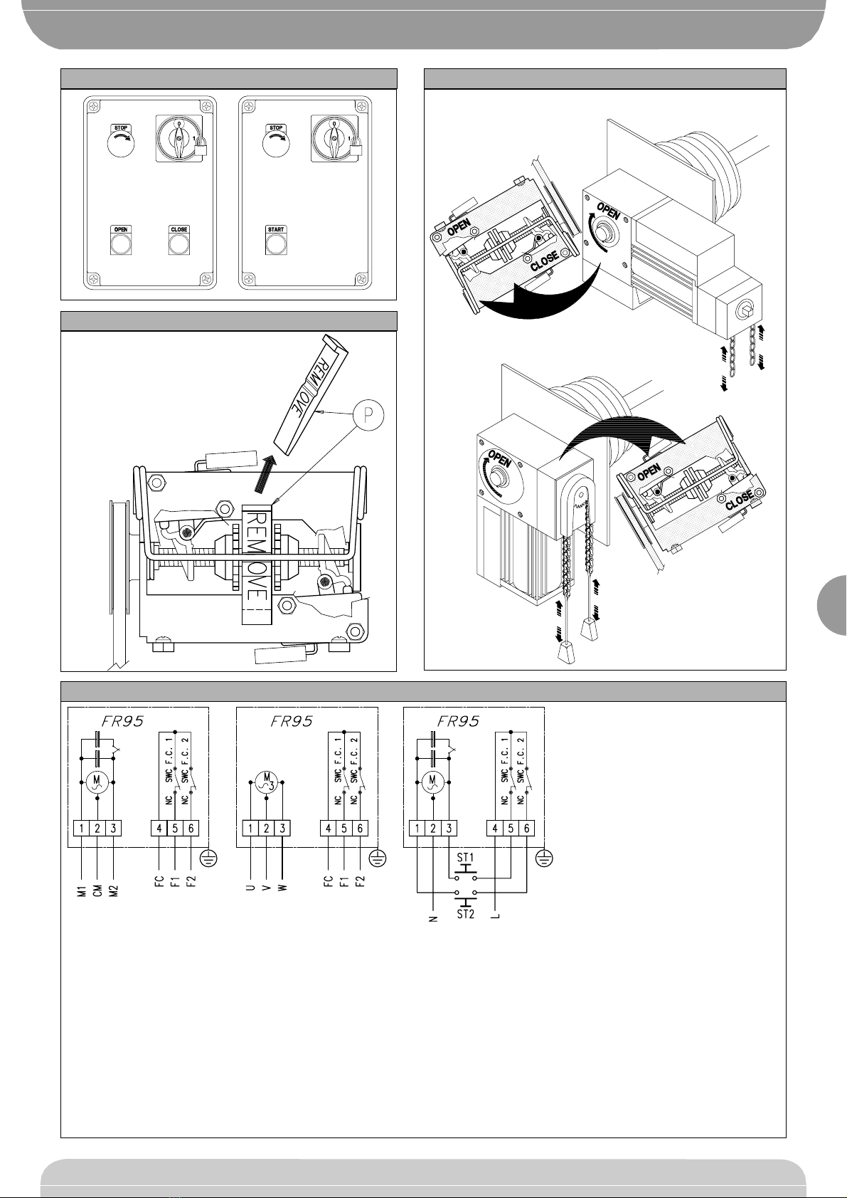
WARNING: Before fastening the controller, check whether the protection
wedge “P” (fig. 10) is present in the adjustment limit switch unit. The protec-
tion wedge prevents damage to the limit switch unit when manual opening
checks are made before adjusting the limiting microswitches.
The controller can be installed on both the right or left of the sectional door.
Direct drive
The cable winder shaft of the sectional door (Ø = 1” Ø 25.4 mm) should have
a key way and can be inserted directly into the through shaft of the controller.
The controller is directly fastened to the cable winder shaft support (fig. 2) or
to the wall using special brackets. Some manufacturers of sectional doors
supply joints with shaft for these types of motor drives.
This type of installation is suitable for sectional doors with cable winders,
which have a diameter not exceeding 80 mm in order to comply with the max-
imum speed of movement required by current standards (e.g.: in Italy the
maximum speed for UNI8612 standards is 8m/min).
Drive with reduction ratio.
The cable winder shaft is driven by a chain drive which may have reduc-
tion gears.
The gearmotor is fastened to the wall by means of the bracket provided
(fig. 3).
The drive dimensions should be in accordance with the diameter of the cable
winder for lifting the sectional door.
The vertical movement speed must correspond to the speed required by cur-
rent standards (e.g.: in Italy the maximum speed for UNI8612 standards is
8m/min).
E.g.: If the sectional door is fitted with a 140mm diameter cable winder, to
obtain an upstroke speed of approx. 8m/min, a crown wheel must be fitted
which has a pitch diameter
Øp= 140mm corresponding to a 36-tooth crown wheel for a 1/2" x 5/16" link
chain.
For this type of installation, a shaft with an 18-tooth pinion for a simple 1/2"
x 5/16" chain (fig. 4) can be supplied as an accessory.
The chain tension is adjusted by moving the motor along the grooves in the
anchoring bracket (fig. 5).
CAUTION: The chain drive should be protected in compliance with current
standards.
5) ELECTRICAL INSTALLATION SET-UP
Arrange the raceways for the connections as shown in fig. 6. Keep the power
supply connections separate from the limit switches connections.
Fit an omnipolar circuit breaker, with a contact opening of at least 3 mm,
which has protection against overloading and can be used to disconnect the
automation from the mains.
The Sirio-FR and Mizar-FR control panels are equipped with lockable cut-out
switches and fuses (fig. 7). A radio control single-twin channel receiver can be
inserted on the control boards.
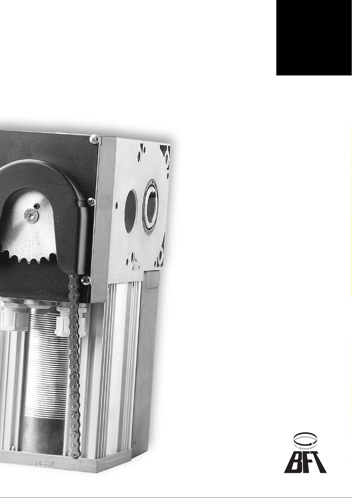
Connection without the control unit can only be carried out in the single-
phase version and for “hold-to-run” control. Only use buttons with at least
10A-250V capacity (fig. 8).
6) CONNECTION TO TERMINAL BOARD
Fig. 8 shows the connection of the single-phase and three-phase gearmotor
to the terminal board.
For the electrical connection to the control unit, reference should be made to
the manual of the control unit.
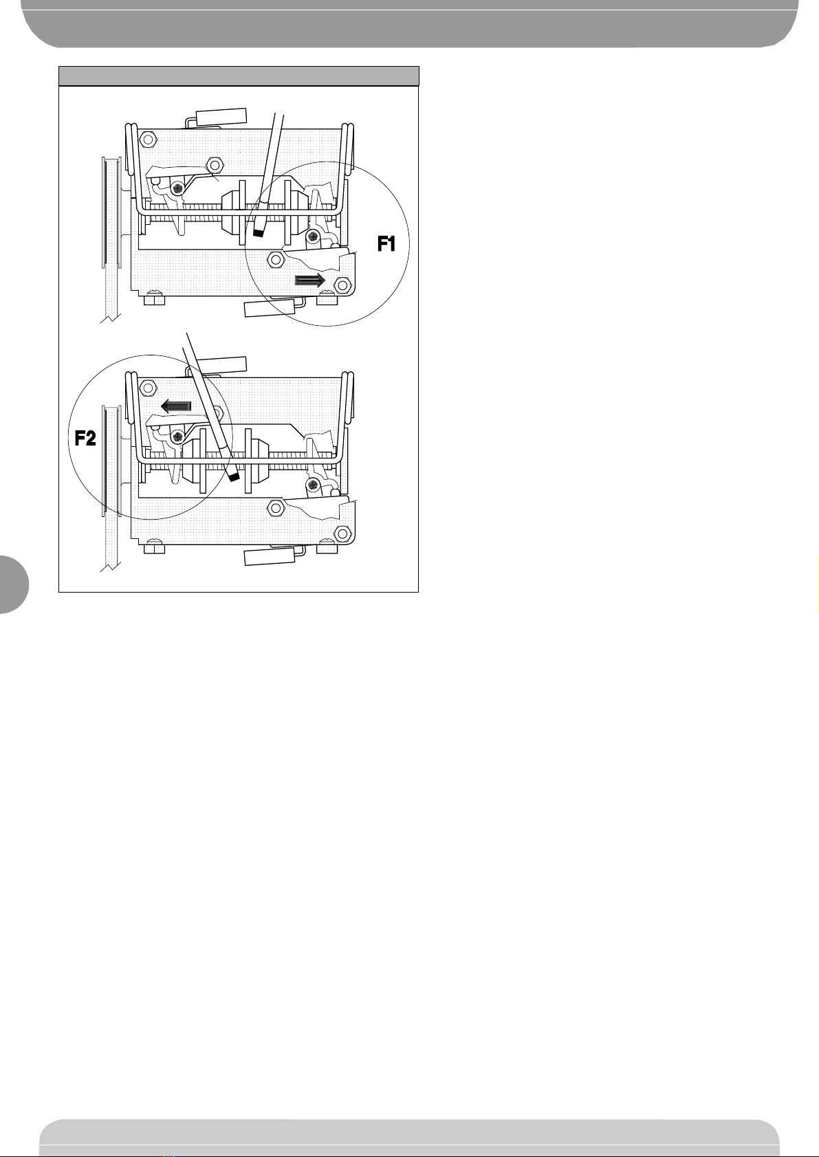
7) LIMIT SWITCH ADJUSTMENT (fig. 9)
The limit switch unit is situated on the head of the drive and is the system of
adjustment. To gain access to the adjustment unit, dismantle the pinion-type
quick release system, if any, and the box which covers the unit.
The microswitches are activated by two toothed cams which are locked in
position by a holding spring.
When the door is closed, the “door closed” adjustment cam should activate
the closing limit switch.
When the door is open, the “opening” adjustment cam should activate the
opening limit switch.
Fig. 9 shows the position of the closing and opening limit switches in relation
to the type of installation carried out.
If the adjustment cams are rotated towards each other, the stroke is
increased. If the adjustment cams are rotated away from each other, the
stroke is decreased.
The limit switch unit is equipped with a protection wedge “P” (fig.10) to pre-
vent damage to the limit switches during manual installation manoeuvres.
8) LIMIT SWITCH CAM ADJUSTMENT
WARNING: For safety reasons, microswitch adjustment must be carried out
with the power supply off.
The adjustment unit is fitted with four microswitches: 2 act as limiting devices
and 2 act as safety overstroke devices.
The overstroke microswitches, if intercepted by the cams, bring the system

321
D811170_03
to a complete halt. This may be caused by an incorrect connection or a faulty
limiting microswitch. If, during installation or maintenance, the cam intercepts
an overstroke microswitch, the system will not accept any commands: the
cam which intercepted the overstroke microswitch must be moved manually
and the reason why the microswitch was intercepted must be established.
Also make sure that the quick release mechanism or the manual chain-open-
ing system have not been activated. Both these manual manoeuvre systems
are equipped with safety microswitches which, if activated, block any electri-
cal command.
To adjust the end of the stroke proceed as follows:
– Close the door manually, keeping it slightly raised above the ground.
– Identify the closing microswitch according to the installation position of the
gearmotor (fig. 9).
– Remove and dispose of the protection wedge “P” which places the limit
switch drive (fig.10) in neutral.
– Lift the holding spring from the cam teeth using a screwdriver (fig. 11).
– Turn the cam in the direction of the closing microswitch until the triggering
of the first limiting microswitch can be heard.
– Lower the spring until it engages with a cam tooth.
– Supply the system with power and give the start command to carry out the
opening manoeuvre.
WARNING: If the motor rotates in the opposite direction, then vary the con-
nections as follows:
– In the single-phase version (fig. 8), invert the two connections in the power
supply terminals of the motor “M1-M2”.
– In the three-phase version (fig. 8), invert two phases in the power supply ter-
minals of the motor “U-V-W”.
– Give the stop command when the door is near to the opening end-of-stroke
stop.
– Disconnect the power supply and lift the holding spring from the cam teeth
using a screwdriver (fig. 11).
– Turn the cam in the direction of the microswitch until the first triggering of
the opening limiting microswitch can be heard.
– Lower the spring until it engages with a cam tooth.
– If the door stops during opening, keep trying to move the cam manually
until complete opening is obtained.
– Check that opening and closing stops are carried out without traction or
compression of the sectional door.
– Repeat the complete opening and closing manoeuvre a few times to check
whether the limiting microswitches are activated correctly. If this is not the
case, adjust the position of the cams as necessary.
– Whenever end-of-stoke adjustments are carried out, the cam holding spring
must always be replaced in the teeth of the two adjustment cams.
– Re-fit all the parts which were previously removed for adjustment of the limit
switches.
9) EMERGENCY MANOEUVRE
If there is no power or because of a breakdown of the system, carry out the
manoeuvre manually according to the system model. The system is equipped
with special microswitches which disconnect the motor automatically during
manual opening or quick release of the door.
FR95-C Manual opening or closing of the door can be obtained by
pulling the jack chain which rotates the motor shaft in the
required direction.
FR95-CM Manual opening or closing by means of the chain can be
obtained in the same way as for model FR95-C. The release
necessary for maintenance operation is obtained by introduc-
ing a CH = 8 mm Allen wrench into the quick release shaft and
rotating it by approx. 90° clockwise. The release disengages
the transmission of the motion to the cable winder shaft of the
door so that the door can be manually operated. As soon as the
shaft is rotated counterclockwise, the mechanical and electrical
connection of the gear-motor is reset.
FR95-SB The door can be released by pulling the cord located on the
right side and rotating the relase shaft by 90° clockwise. The
door can be manually operated when it is perfectly balanced.
10) AUTOMATION CHECK
Before making the automation definitely operative, carefully check the follow-
ing:
Check that all components are safely mounted in the right positions.
Check the correct functioning of all safety devices (limit microswitches, pho-
tocells, sensitive cushions etc.).
Check that the thrust (anticrushing) force of the door stops the system with-
in the limits foreseen by the regulations in force.
Check the emergency function control.
Check the opening and closing operation with the applied control devices.
Check the electronic logic of normal and personalised functioning, in the
event that a control unit is installed.
11) USE OF THE AUTOMATION
As the automation can be controlled at a distance by means of remote con-
trol or start push-button, and therefore not at sight, it is indispensable to con-
trol frequently the perfect efficiency of all safety devices. For any functioning
anomaly, intervene rapidly even with the help of qualified personnel. We rec-
ommend to keep children at a suitable distance from the range of action of
the automation.
12) CONTROL
The use of the automation allows the opening and closing of the door in a
motorised way. The control can be of different types (manual, with remote
control, access control with magnetic badge etc.) according to the necessity
and the characteristics of the installation. For the various control systems, see
the relative instructions.
The users of the automation must be instructed about its control and use.
13) MAINTENANCE
For any maintenance, disconnect the system from the power supply.
Check periodically for oil leakages from the radiator.
Check the condition of the toothed belt of the limiting devices and replace it
if damaged.
Check periodically the drive unit and lubricate it as much as necessary (only
for chain reduced transmission).
Check all the safety devices of the door and motor unit.
For any functioning anomaly, not solved, disconnect the system from the
power supply and request the intervention of qualified personnel (installer).
During the out of order period, activate the manual release in order to allow
the manual opening and closing.
FR95
FR95
AUTOMATION FOR INDUSTRIAL SECTIONAL DOORS

322
D811170_03
Fig. 1 NEW Fig. 2 NEW
Fig. 3
Fig. 5
Fig. 6
Fig. 7
Fig. 4
PG11
PG11
PG11
mm2
mm2
FR95
FR95
AUTOMATION FOR INDUSTRIAL SECTIONAL DOORS

323
D811170_03
Fig. 8
Fig. 11
Fig. 10
Fig. 9
M1 = Marcia motore e condensatore
Motor and capacitor start
Marche moteur et condensateur
Lauf Motor und Kondensator
Marcha motor y condensator
M2 = Marcia motore e condensatore
Motor and capacitor start
Marche moteur et condensateur
Lauf Motor und Kondensator
Marcha motor y condensator
CM = Comune motore
Common motor
Commun moteur
Gemeinsamer
Motor común
F1= Fine corsa di apertura o chiusura
Opening-closing limit switch N.C.
Fin de course d'ouverture ou fermeture N.C.
Endanschlag Oeffnung oder Schliebung N.C.
Fin derecorrido de abertura o cierre N.C.
F2= Fine corsa di apertura o chiusura
Opening-closing limit switch N.C.
Fin de course d'ouverture ou fermeture N.C.
Endanschlag Oeffnung oder Schliebung N.C.
Fin derecorrido de abertura o cierre N.C.
FC= Comune finecorsa
Common limit switch
Commun fin de course
Gemeinsamer Draht Endanschlag
Fin de recorrido común
U-V-W= Trifase
Three-phase
Triphasé
Dreiphasig
Trifásica
ST1-ST2= Pulsanti comando
Command push buttons
Boutons de start
Startknöpfe
Mandos de apertura y cierre
FR95
FR95
AUTOMATION FOR INDUSTRIAL SECTIONAL DOORS

324
D811170_03
Fig. 12
FR95
FR95
AUTOMATION FOR INDUSTRIAL SECTIONAL DOORS
This manual suits for next models
3
Table of contents
Other BFT Door Opening System manuals