manuals.online logo
Brands
  1. Home
  2. •
  3. Brands
  4. •
  5. Bircher Reglomat
  6. •
  7. Security Sensor
  8. •
  9. Bircher Reglomat US beam Supplement

Bircher Reglomat US beam Supplement

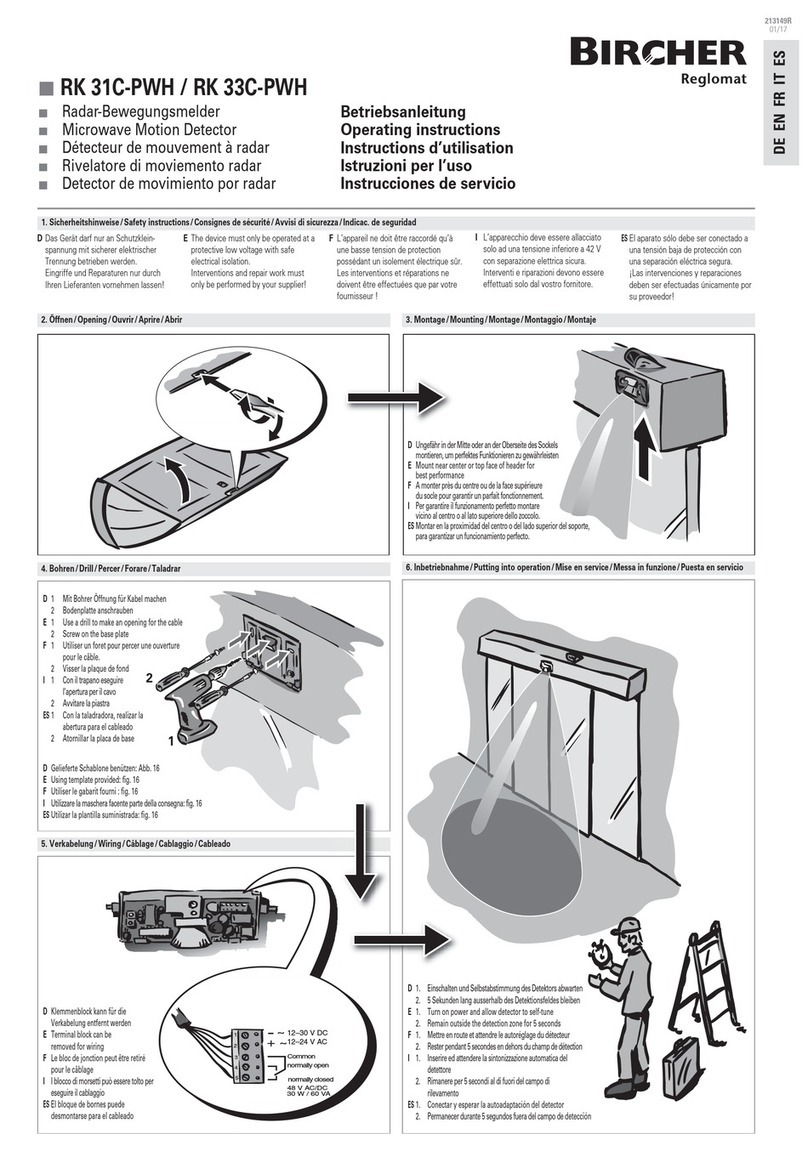
Ini ialisa ion (see opera ing ins ruc ions, chap er 4)
Reglobeam remo e con rol
Bircher Regloma AG, headquarters Switzerland Tel. +41 (0)52 687 11 11, Germany Tel. +49 (0)7031 70 60 0
Elec rical connec ions
Se ings wi h Reglobeam
Ins alla ion and adjus men
1. Fit housing (see operating instructions, chapter 2).
2. Click US beams into aluminium profiles.
3. Check whether the US beams are clicked in correctly and therefore secured
well in the profile!
3. . Position US beams and set inclination angle
The left and right bearing clamps must be at the same angle
(see operating instructions, chapter 4.3).
4. f several sensors are used, connect these with the ribbon cable
(see operating instructions, chapter 4.1).
5. Click cover onto profile (working from front to back) and ensure that the
US beam's inclination angle doesn't change!
1
2
3
4
5
6
common
nc*
no*
Test input
Diagram for door side A or B: Diagram for door controller with Y adapter:
General:
f Gflashes, a connection to the sensor could not be established.
Disconnect the power supply of the UniScan briefly or press the two
buttons on the sensor for 1 second.
Direct the Reglobeam remote control more exactly and directly at the
sensor.
30 minutes after the last setting was undertaken on the sensor,
configuration mode is automatically exited.
a) nitialisation is undertaken by pressing the keys F + 3 + 6 on the Reglobeam remote control or by pressing the green key for 5 seconds!
b) f both LEDs (red/green) flash, this indicates that the function has been triggered. The detection area must be exited within 6 seconds.
c) f the red LED then flashes, this indicates that initialisation is under way. The detection area must not be entered during this time!
d) nitialisation is complete when both LEDs go out.
Key Function Key Brief description of function
A Test input
1
2
3
4
5
«High» active, pull up
«High» active, pull down
«Low» active, pull up
«Low» active, pull down
Test input deactivated*
B
Switch light points on and off
Note: Once one or more beams have been
switched on and off, re-initialise using F+3+6
1+ 1 oder 2
2+ 1 oder 2
3+ 1 oder 2
4+ 1 oder 2
5+ 1 oder 2
6+ 1 oder 2
7+ 1 oder 2
8+ 1 oder 2
9
Beam 1 selected, activate with key 1, deactivate with key 2
All beams on Factory setting: Energy-saving beam pattern 1-3-5-7-8 on
C Output signal
1
2
6
The relay picks up when a detection takes place (active)
The relay drops out when a detection takes place (passive)
Restart
D Sensitivity
1
2
3
4
5
6
7
Object height > 10 cm
Object height > 20 cm if sensor mounting height is up to 3 m
Object height > 20 cm if sensor mounting height is up to 2.7 m
Object height > 30 cm**
Object height > 50 cm**
Object height > 70 cm**
Object height > 100 cm*
Factory setting, *Setting not TÜV-compliant regarding type approval, **above a mounting height of 2.7 m, setting not TÜV-compliant regarding type approval
This information sheet does not replace the
original operating instructions!
Read the operating instructions before
commissioning the device!
Note:
Single operation is only possible
with an alternating current supply!
Page 1 of 2
Short guide
UniScan / US beam
1
test input
2no
3nc
4 common
5
–⁄~
6 +/
~
7common
8 nc
9no
10
test input
6
5
4
3
2
1
1
2
3
4
5
6
common
common
nc
nc
no
no
test input
test input
To sensor master
on the front of the
door (hinge side of
the door)
To sensor master
on the back of the
door(non-hinge side
of the door)
To door controller

Area properties
The dimensions of the detection area
correspond to a mounting height of 2.2 m
2.9 cm 3.4 cm 9.2 cm
5.7 cm
47.1 cm
Positioning
W= Profile and door width
W1= Monitored area, total area width
XL = Area overlap
x
= Maximum permitted spacing so that
standard test body CA (D N 18650:2005)
is still detected.
H= Mounting height
n= Number of sensors per door panel
P= Points on sensor to be deactivated 
W
Ribbon cable connection
Door controller
XL x
d3d2d1
D
W1
u1x4w3v2
H
W 70 80 90 100 110
W1 57 67 77 87 97
H D nXL P d1 d2 d3 nXL P d1 d2 d3 nXL P d1 d2 d3 nXL P d1 d2 d3 nXL P d1 d2 d3
170 36 2–16 3 2 – – 2–6 0 12 – – 24 0 22 – – 3–16 2 1 1 – 3–12 2 5 7 –
180 39 2–20 3 2 – – 2–10 1 12 – – 20 0 22 – – 210 0 32 – – 3–19 3 3 9 –
190 41 2–24 4 2 – – 2–14 2 12 – – 2–4 0 22 – – 26 0 32 – – 3–24 4 2 10 –
200 43 2–29 4 2 – – 2–19 3 12 – – 2–9 1 22 – – 21 0 32 – – 3–28 5 2 10 –
210 45 2–33 5 2 – – 2–23 3 12 – – 2–13 1 22 – – 2–3 0 32 – – 27 0 42 – –
220 47 2–37 5 2 – – 2–27 4 12 – – 2–17 2 22 – – 2–7 0 32 – – 23 0 42 – –
230 49 2–41 6 2 – – 2–31 4 12 – – 2–21 3 22 – – 2–11 1 32 – – 21 0 42 – –
240 51 2–46 6 2 – – 2–36 5 12 – – 2–26 3 22 – – 2–16 2 32 – – 26 0 42 – –
250 53 2–50 7 2 – – 2–40 5 12 – – 2–30 4 22 – – 2–20 2 32 – – 210 1 42 – –
260 56 2–54 7 2 – – 2–44 6 12 – – 2–34 4 22 – – 2–24 3 32 – – 214 1 42 – –
270 58 1–1 0 – – – 2–49 6 12 – – 2–39 4 22 – – 2–29 3 32 – – 219 2 42 – –
280 60 1–3 0 – – – 2–53 6 12 – – 2–43 5 22 – – 2–33 3 32 – – 223 2 42 – –
290 62 1–5 0 – – – 2–57 7 12 – – 2–47 5 22 – – 2–37 4 32 – – 227 3 42 – –
300 64 1–7 0 – – – 2–61 7 12 – – 2–51 6 22 – – 2–41 4 32 – – 231 3 42 – –
W 120 130 140 150 160
W1 107 117 127 137 147
H D nXL P d1 d2 d3 nXL P d1 d2 d3 nXL P d1 d2 d3 nXL P d1 d2 d3 nXL P d1 d2 d3
170 36 3–12 2 5 17 – 3–2 0 15 17 – 38 0 25 17 – 4–16 3 2 4 17 4–9 1 9 7 17
180 39 3–19 3 3 19 – 3–9 1 13 19 – 31 0 23 19 – 4–20 3 20 2 19 4–17 3 5 9 19
190 41 3–25 4 1 21 – 3–15 2 11 21 – 3–5 0 21 21 – 35 0 31 21 – 4–25 4 2 10 21
200 43 3–21 3 9 13 – 3–21 3 9 23 – 3–11 1 19 23 – 3–1 0 29 23 – 39 0 39 23 –
210 45 3–27 4 7 15 – 3–27 4 7 25 – 3–17 2 17 25 – 3–7 0 27 25 – 33 0 37 25 –
220 47 3–34 5 5 17 – 3–34 5 5 27 – 3–24 3 15 27 – 3–14 1 25 27 – 3–4 0 35 27 –
230 49 29 0 52 – – 3–40 6 3 29 – 3–30 4 13 29 – 3–20 2 23 29 – 3–10 1 33 29 –
240 51 24 0 52 – – 3–46 6 2 30 – 3–36 5 12 30 – 3–26 3 22 30 – 3–16 2 32 30 –
250 53 20 0 52 – – 3–43 6 9 23 – 3–42 6 10 32 – 3–32 4 20 32 – 3–22 2 30 32 –
260 56 2–4 0 52 – – 26 0 62 – – 3–49 6 8 34 – 3–39 5 18 34 – 3–29 3 28 34 –
270 58 2–9 0 52 – – 21 0 62 – – 3–55 7 6 36 – 3–45 5 16 36 – 3–35 4 26 36 –
280 60 2–13 1 52 – – 2–3 0 62 – – 27 0 72 – – 3–51 6 14 38 – 3–41 5 24 38 –
290 62 2–17 1 52 – – 2–7 0 62 – – 23 0 72 – – 3–57 7 12 40 – 3–47 5 22 40 –
300 64 2–21 2 52 – – 2–11 0 62 – – 2–1 0 72 – – 3–64 7 10 42 – 3–54 6 20 42 –
Measurement in [cm] Page 2 of 2
Settings
UniScan
Key Function Key Brief description of function
E Relay hold interval
1
2
3
4
5
6
7
0 ms
50 ms
200 ms
1 s
3 s
6 s
10 s
F + 1 Device address 1–7 Address of between 1 and 7 can be selected, factory setting is 3
F + 2 Composition of the floor
1
2
3
tandard floor
Dark or reflective floor
Metal grating*
F + 4 Synchronisation mode 1
2
On
Off
F + 8 Enhanced levels 1 Restore the factory default setting
(ms=milliseconds, s=seconds)
267179 10/10

This manual suits for next models

1

Other Bircher Reglomat Security Sensor manuals

Bircher Reglomat MERKUR User manual

Bircher Reglomat

Bircher Reglomat MERKUR User manual

Bircher Reglomat EsGate 2 User manual

Bircher Reglomat

Bircher Reglomat EsGate 2 User manual

Bircher Reglomat RBM 2 User manual

Bircher Reglomat

Bircher Reglomat RBM 2 User manual

Bircher Reglomat ProLoop 2 User manual

Bircher Reglomat

Bircher Reglomat ProLoop 2 User manual

Bircher Reglomat Herkules 2 User manual

Bircher Reglomat

Bircher Reglomat Herkules 2 User manual

Bircher Reglomat Herkules 2E User manual

Bircher Reglomat

Bircher Reglomat Herkules 2E User manual

Bircher Reglomat ProLoop User manual

Bircher Reglomat

Bircher Reglomat ProLoop User manual

Bircher Reglomat Reflex ES User manual

Bircher Reglomat

Bircher Reglomat Reflex ES User manual

Bircher Reglomat Hercules 2 User manual

Bircher Reglomat

Bircher Reglomat Hercules 2 User manual

Bircher Reglomat RK 31C-PWH User manual

Bircher Reglomat

Bircher Reglomat RK 31C-PWH User manual

Bircher Reglomat MERKUR SE User manual

Bircher Reglomat

Bircher Reglomat MERKUR SE User manual

Bircher Reglomat PrimeScan B Supplement

Bircher Reglomat

Bircher Reglomat PrimeScan B Supplement

Bircher Reglomat Jupiter User manual

Bircher Reglomat

Bircher Reglomat Jupiter User manual

Bircher Reglomat PrimeTec B User manual

Bircher Reglomat

Bircher Reglomat PrimeTec B User manual

Bircher Reglomat Merkur 2 Series User manual

Bircher Reglomat

Bircher Reglomat Merkur 2 Series User manual

Bircher Reglomat PrimeMotion B User manual

Bircher Reglomat

Bircher Reglomat PrimeMotion B User manual

Bircher Reglomat PrimeTec B User manual

Bircher Reglomat

Bircher Reglomat PrimeTec B User manual

Bircher Reglomat PrimeMotion C User manual

Bircher Reglomat

Bircher Reglomat PrimeMotion C User manual

Bircher Reglomat ProxySwitch User manual

Bircher Reglomat

Bircher Reglomat ProxySwitch User manual

Bircher Reglomat Swissdoor PrimeMotion B User manual

Bircher Reglomat

Bircher Reglomat Swissdoor PrimeMotion B User manual

Bircher Reglomat ProLoop User manual

Bircher Reglomat

Bircher Reglomat ProLoop User manual

Bircher Reglomat ProLoop Lite User manual

Bircher Reglomat

Bircher Reglomat ProLoop Lite User manual

Bircher Reglomat DI1-Pro V2 User manual

Bircher Reglomat

Bircher Reglomat DI1-Pro V2 User manual

Bircher Reglomat ESM User manual

Bircher Reglomat

Bircher Reglomat ESM User manual

Popular Security Sensor manuals by other brands

WT sensor PC12K quick start guide

WT sensor

WT sensor PC12K quick start guide

Electra e11 manual

Electra

Electra e11 manual

IFM SBZ224 operating instructions

IFM

IFM SBZ224 operating instructions

Dorr HA-150 instruction manual

Dorr

Dorr HA-150 instruction manual

Klein Tools ET120 instruction manual

Klein Tools

Klein Tools ET120 instruction manual

KRAUSE ProTec Instructions for assembly

KRAUSE

KRAUSE ProTec Instructions for assembly

Honeywell 5800COMBO-CN installation guide

Honeywell

Honeywell 5800COMBO-CN installation guide

Siemens 5TC1700 operating instructions

Siemens

Siemens 5TC1700 operating instructions

DSC The NEW FORCE 2 F2-210 installation instructions

DSC

DSC The NEW FORCE 2 F2-210 installation instructions

Schweitzer Engineering Laboratories AR-OH installation instructions

Schweitzer Engineering Laboratories

Schweitzer Engineering Laboratories AR-OH installation instructions

Solutions UWT NivoGuide 8200 Technical Information/Instruction manual

Solutions

Solutions UWT NivoGuide 8200 Technical Information/Instruction manual

Ecolink NanoFIL manual

Ecolink

Ecolink NanoFIL manual

Velleman PIR1200W manual

Velleman

Velleman PIR1200W manual

Heiman HEIEHS1SA quick start guide

Heiman

Heiman HEIEHS1SA quick start guide

Hiltron security IR10 instructions

Hiltron security

Hiltron security IR10 instructions

MPH Industries SpeedLaser B user manual

MPH Industries

MPH Industries SpeedLaser B user manual

Satel GREY manual

Satel

Satel GREY manual

Bornack Stripe Comfort Click user manual

Bornack

Bornack Stripe Comfort Click user manual

manuals.online logo
manuals.online logoBrands
  • About & Mission
  • Contact us
  • Privacy Policy
  • Terms and Conditions

Copyright 2025 Manuals.Online. All Rights Reserved.