Bowa ERGO 300 Specification sheet
EN ERGO 300 – Morcellator
Information for use
12930 - S0 EN

Instructions for use, ERGO - BOWA- IFU-- ERG-S-EN-

Instructions for use, ERGO - BOWA- IFU-- ERG-S-EN-
Table of Content
1 General information 4
1.1 Indications 4
1.2 Principle 4
1.3 Contraindications 4
1.4 Target group 4
1.5 Medical application 5
1.6 On receipt 5
1.7 Scope of delivery, accessories and spare parts 6
1.8 Technical data: ERGO 300 – Morcellator 7
1.9 Ambient conditions 7
1.10 Warranty 7
1.11 Technical changes reserved 7
2 Explanation of symbols 8
3 Safety information 9
3.1 EMC, Manufacturer’s Declaration of Conformity 9
3.2 Modification and misuse 9
3.3 In the event of a serious incident 9
3.4 Essential requirements 10
3.5 During use 10
4 Device overview 11
4.1 System-Chart, ERGO 300 – Morcellator 13
5 Before use 14
5.1 Potential equalization connection according to DIN 42801 14
5.2 Connection to the power supply 14
5.3 Device preparation 14
5.3.1 Mounting the morcellator set with protective tube (according to option 1) 15
5.3.2 Assembly of the Morcellator set with Trocar Cannula (according to option 2) 18
5.3.3 Mounting a grasping forceps (according to option 3) 21
5.4 Mains connection 21
6 Operation 22
6.1 Using the control unit 22
6.2 Execution 24
6.2.1 Option 1: Morcellation with protective tube 26
6.2.2 Option 2: Morcellation with Trocar Cannula 27
6.2.3 Option 3: Myomektomy 29
6.3 After use 30
6.4 Disassembly of the Trocar Cannula 31
6.5 Disassembly of the motor 32
6.6 Disassembly of gear unit and Morcellator with protective tube 32
7 Instrument preparation 33
7.1 Control unit and pedal 33
7.2 The following instruments must be reprocessed 34
8 Maintenance and repair 38
8.1 General maintenance 38
8.2 Replacing the control unit fuse 39
8.3 Safety inspections 39
8.4 Malfunction and troubleshooting 40
8.5 Fault messages on the display 41
8.6 Spare parts list with order number 42
8.7 Information on disposal 42
Appendix 43
Electromagnetic Compatibility (EMC) 44
Declaration of Conformity 47
Manufacturer and service points 49

Instructions for use, ERGO - BOWA- IFU-- ERG-S-EN-
1General information
1.1 Indications
Morcellator set for morcellation and extraction of tissue and for removing myomas or the uterus during laparoscopic pro-
cedures in gynecology.
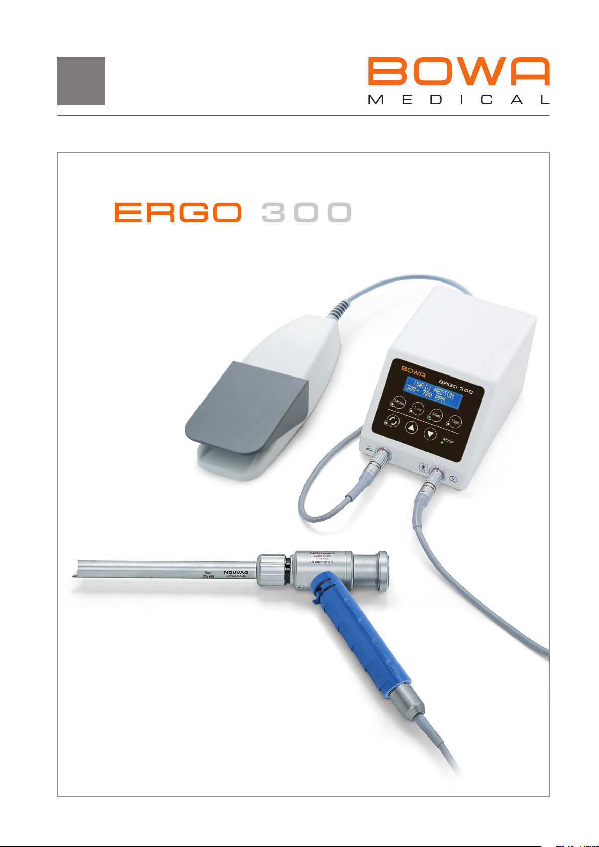
1.2 Principle
The ERGO - Morcellator is a control unit for the Nouvag Morcellator for use in morcellation and extraction of tissue
as well as for myoma removal at laparoscopic interventions. A rotating cylindrical tube with a blade at the distal end is
inserted through an abdominal cavity that has been enlarged by an Insufflator. The tissue that is to be removed is guided to
the cutting tube by a gripper, cut off and removed through the tube.
This manual describes three different options for removing tissue by a laparoscopic procedure.
Option 1: Tissue removal by morcellation with protective tube
Instruments (gripper) are inserted through a protective tube sealed by a valve system. The valve can be covered by a thumb
for removing the gripper from the sealed protective tube to prevent gas loss.
Option 2: Tissue removal by morcellation with Trocar Cannula
Instruments (cutter tube, gripper) are inserted through the Trocar Cannula. The Trocar Cannula contains a valve that pre-
vents gas loss when withdrawing the instruments.
Option 3: Tissue removal (myomectomy) with myoma drill through the Trocar Cannula
Insertion of the myoma drill through the Trocar Cannula (Ø mm) with separate access. Removal of tissue by the Morcel-
lator with grasping forceps according to option or .
For a myomectomy only the Trocar Cannula (REF nou) with a diameter of mm may be used in connection with the
myoma drill.
1.3 Contraindications
Relative or absolute contraindications may result from the general medical findings or in special cases in
which the patient’s risk for motor-driven tools is significantly increased. Ovaries, fallopian tubes, myomata
and other structures must be devascularized and dissected before morcellation.
The laparoscopic deployment of morcellators is contraindicated:
• for treatment of malignant tumors
• for treatment of vascularized tissue
• for preparation of tissue
• in gynecologic surgery in which tissue to be morcellated is known or suspected to contain malignacy
• for removal of uterine tissue containing fibroids in patients who are:
• Peri or postmenopausal, or
• Candidates for en bloc tissue removal, for example through the vagina or via a mini-laparotomy incision.
• Cases described in the literature, must be observed.
1.4 Target group
Younger women between and years of age. From the age of , the risk is increased, but an operation by morcellation
is still possible.
1
8
9
10
7
5
4
3
2
11
12
6
Instructions for use, ERGO - BOWA- IFU-- ERG-S-EN-
1.5 Medical application
This product is designed solely for use in medical facilities by medically qualified persons.
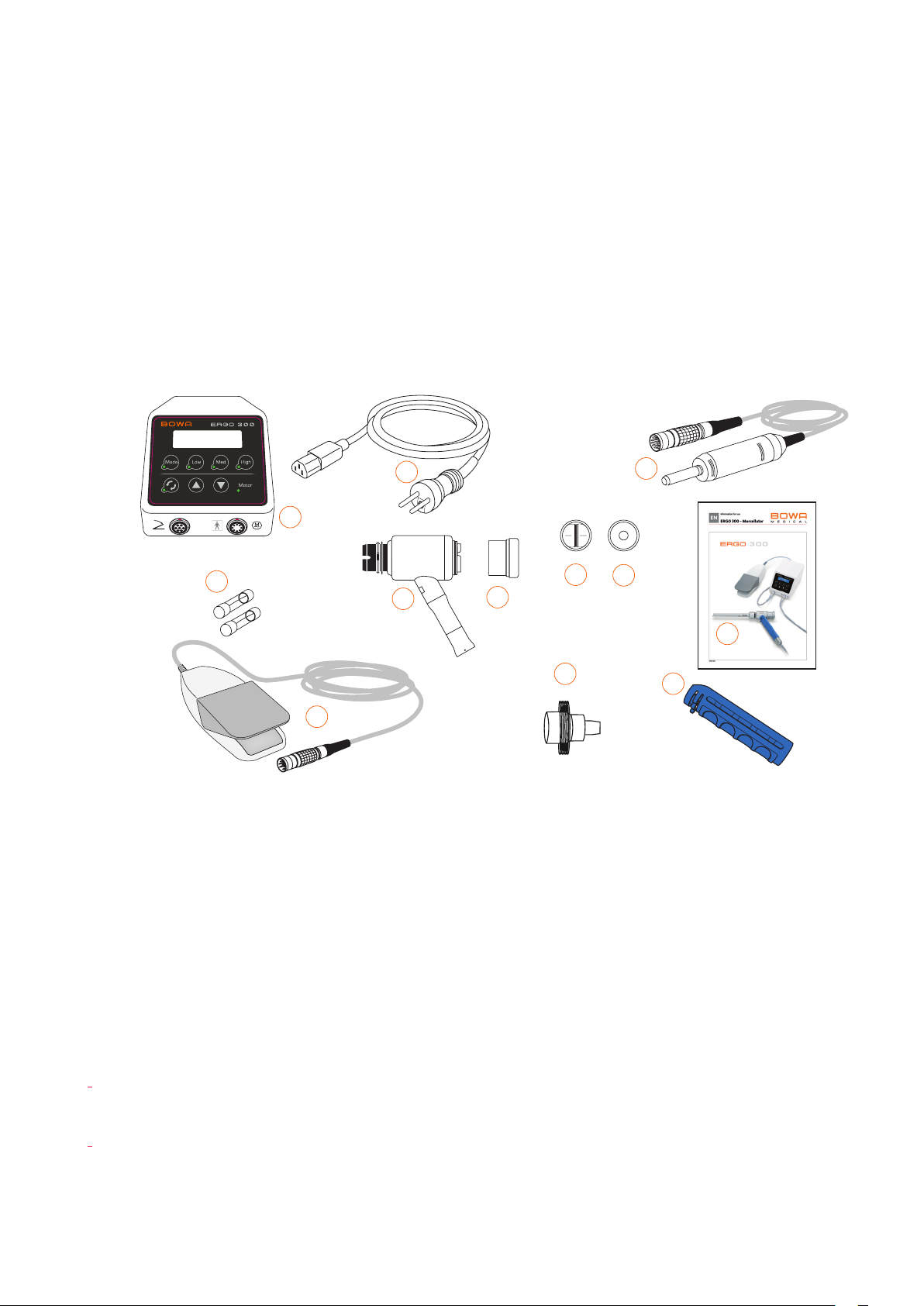
1.6 On receipt
• The shipping package must contain all parts listed in chapter “. Scope of delivery”.
• If any parts are damaged or missing, contact the Nouvag agent from which the device was ordered or
Nouvag AG.
Immediate inspection of the ERGO 300 - Morcellator - motor system set (REF 3287bow):
. Control unit (-)
. Power cable, country-specific
. Gear unit (-)
. Seal unit (bow)
. roof shaped seals (-)
. membrane seals for all cutting tube diameters
(-)
. Electronic motor (-)
. fuses ()
. Vario pedal (-)
. Threaded spray adapter (-) for NouvaOil
spray for the care of the electronic motor
. Handle (-)
. Printed IFU ()

Instructions for use, ERGO - BOWA- IFU-- ERG-S-EN-
1.7 Scope of delivery, accessories and spare parts
REF Description Quantity
905-000 ERGO 300 – Morcellator set comprises the following products...........................................................................1
- ERGO Morcellator control unit, device connecting cable m, country specific......................................................
- Vario pedal; IPX; connecting cable m .....................................................................................................................................
- Electronic motor , m motor cable ..........................................................................................................................................
- Morcellator gear unit .......................................................................................................................................................................
- Handle, complete..............................................................................................................................................................................
bow Information for use (IFU)................................................................................................................................................................
- Threaded adapter for NouvaOil-Spray (REF ) for the care of the electronic motor ............................................
Accessories and spare parts according to option 1:
- Protective tube, Ø mm ...............................................................................................................................................................
- Cutting tube, Ø mm.....................................................................................................................................................................
- Obturator, Ø mm..........................................................................................................................................................................
- Protective tube, Ø mm................................................................................................................................................................
- Cutting tube, Ø mm.....................................................................................................................................................................
- Obturator, Ø mm..........................................................................................................................................................................
bow Replacement sealing unit (small) for cutting tube Ø / mm, incl. membrane seal and roof shaped seal.........
- Set of roof seals (transparent) for cutting tube Ø / mm..........................................................................................
- Set of membrane seals (blue) for cutting tube Ø // mm....................................................................................
Accessories and spare parts according to option 2:
bow Trocar Cannula for Ø mm instruments...................................................................................................................................
bow Trocar Cannula for Ø mm instruments ...................................................................................................................................
bow Seals for Trocar Cannula...............................................................................................................................................................
bow O-ring for Trocar Cannula............................................................................................................................................................
bow Sealing adapter for mounting the small sealing unit on the Trocar Cannula .....................................................................
bow Replacement sealing unit (small) for cutting tube Ø / mm, incl. membrane seal and roof seal .......................
Accessories and spare parts according to option 3:
- Trocar Cannula for Ø mm instruments for myoma drills with Ø mm ........................................................................
bow Sealing adapter for mounting the small sealing unit on the Trocar Cannula .....................................................................
bow Replacement sealing unit (small) for cutting tube Ø / mm, incl. membrane seal and roof seal .......................
In line with regulations pertaining to hazardous materials, the item NouvaClean spray (REF ) and NouvaOil spray
(REF ) is not delivered with the control unit but can be ordered separately from any official Nouvag service center.
www.nouvag.com

Instructions for use, ERGO - BOWA- IFU-- ERG-S-EN-
1.8 Technical data: ERGO 300 - Morcellator
Voltage variable: ...................................................................................................................................... V~/ V~/ V~, / Hz
Fuses, power supply ................................................................................................................................................... fuses T AL, V AC
Power consumption .................................................................................................................................................................................... VA
Maximum motor speed................................................................................................................................................................... , rpm
Maximum motor torque ............................................................................................................................................................................ Ncm
Maximum torque at transmission outlet....................................................................................................................................... Ncm **
Motor coupling ........................................................................................................................................................INTRA-coupling, ISO
Motor cable length ........................................................................................................................................................................................... m
Pedal cable length............................................................................................................................................................................................. m
Morcellator speed range............................................................................................................................................................ – rpm
Type of applied part.............................................................................................................................................................................. Type BF *
Protection class............................................................................................................................................................................................ Class I
Pedal ...................................................................................................................................................................................................................IPX
Dimensions (W x D x H) .................................................................................................................................................... x x mm
Net weight of control unit ........................................................................................................................................................................... kg
* Applied part is the Morcellator
** Maximum torque is delivered at the speed range of 200 - 400 rpm.
1.9 Ambient conditions
Transport and storage: Operation:
Relative humidity: Max.
Temperature: – °C ( – °F) – °C ( – °F)
Atmospheric pressure: – hPa – hPa
1.10 Warranty
Purchasing the ERGO - Morcellator entitles you to a -year warranty. If you return the warranty card for registration
within four weeks of the date of purchase, warranty coverage will be extended for a further months. Improper use or
repair, or failure to observe these instructions, will relieve us from any obligation arising from warranty provisions or other
claims.
1.11 Technical changes reserved
Through further developments, illustrations, dimensions, weights and technical data may differ slightly. Changes and literal
errors reserved.
Instructions for use, ERGO - BOWA- IFU-- ERG-S-EN-
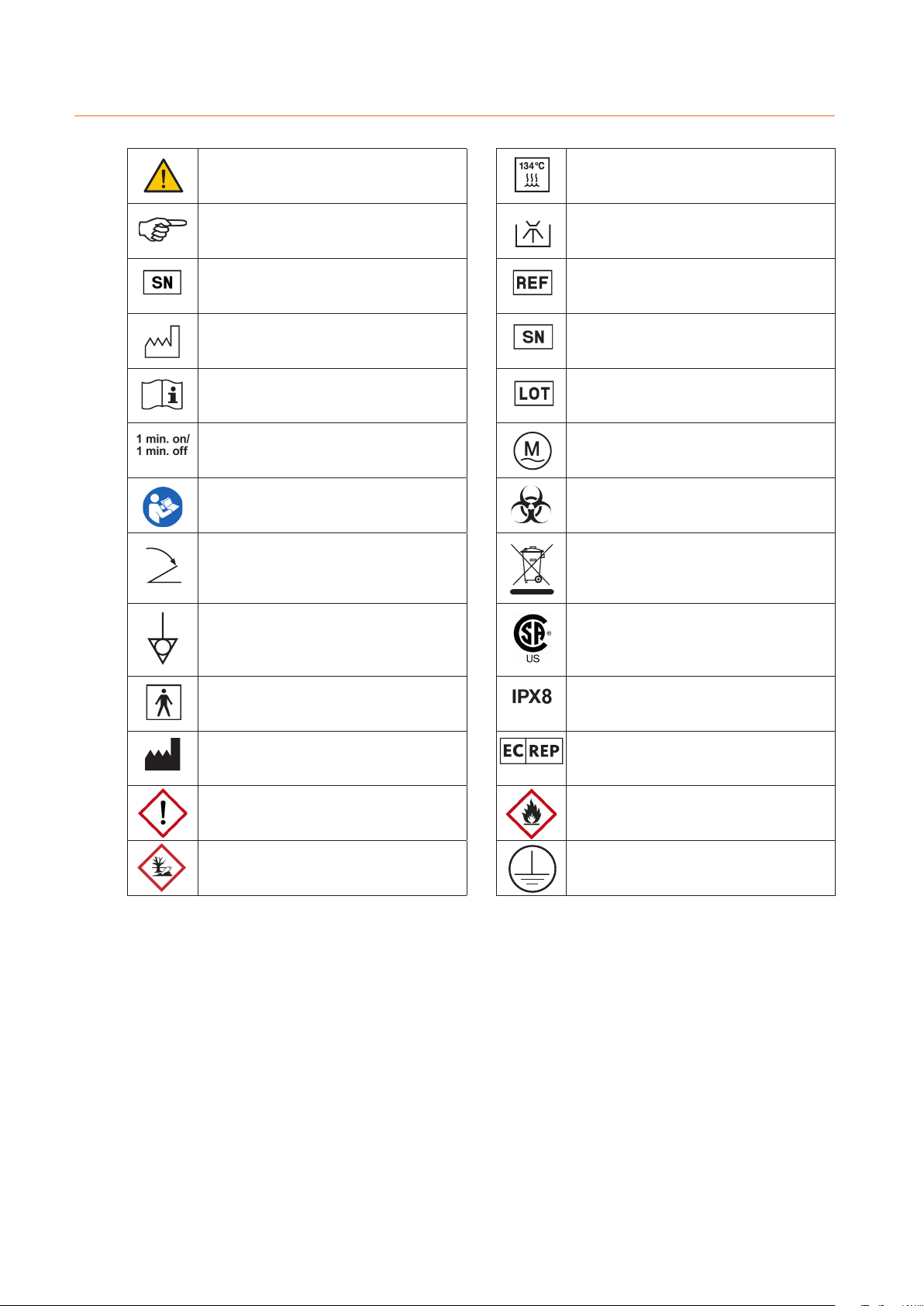
2Explanation of symbols
Warning Autoclavable at °C
Note Suitable for thermal disinfection
Manufacturer Symbol indicating the order number
Date of manufacturing Symbol indicating the serial number
Pay attention to the accompanying documents Symbol indicating the LOT-number
Intermittent operation: 1 min. ON / 1 min. OFF for
8 cycles, brake of 15 min.
Symbol for the motor connection socket
Refer to operating instructions Biohazard
Pedal Disused electrical and electronic equipment
is hazardous waste and must not be disposed
of with household waste. The local disposal
regulations apply.
Potential equalization connection Certified by the Canadian Standards Association
(CSA).regulations apply.
Applied part of type BF is the Morcellator Protected against continuous submersion in
water.
Manufacturer European authorized representative
Dangerous goods aerosol sprays:
Warning!
NouvaClean/NouvaOil
Dangerous goods aerosol sprays:
Extremely flamable
NouvaClean/NouvaOil
Dangerous goods aerosol spray:
Environmentally hazardous
NouvaClean/NouvaOil
Protective ground

Instructions for use, ERGO - BOWA- IFU-- ERG-S-EN-
3Safety information
Your safety, the safety of your team, and of course that of your patients is very important to us. It is therefore essential to
bear the following information in mind:
Every use of the ERGO - Morcellator different to the product description defined in chapter “Intended use and oper-
ation”, causes risks for patients and trained personnel. If physical examinations and therapies are carried out without use
of the devices then the devices must be removed from the place of treatment. Avoid any connection or close adjacency to
other devices.
3.1 EMC, Manufacturer’s Declaration of Conformity
The use of (RF) Radio Frequency emitting devices and equipment as well as the occurrence of negative environmental
factors in the close area of the ERGO - Morcellator may cause unexpected or adverse operation. The connection or the
placing of other devices in close vicinity is not allowed.
The EMISSIONS characteristics of this equipment make it suitable for use in industrial areas and hospitals (CISPR class
A). If it is used in a residential environment (for which CISPR class B is normally required) this equipment might not offer
adequate protection to radio-frequency communication services. The user might need to take mitigation measures, such as
relocating or re-orienting the equipment.
Use only accessories and cables as specified in the product description. Further observe the EMC manufacturers declara-
tion of conformity.
3.2 Modification and misuse
• Modification or manipulation of the ERGO - Morcellator and its accessories is prohibited. The manufacturer is not
liable for any damages resulting from unauthorized modifications or manipulations. The warranty will be canceled.
• Use of the ERGO - Morcellator outside the indications described in Section . is prohibited.
The user or operator is solely responsible for any such use.
3.3 In the event of a serious incident
Any serious incident or problem with the device must be reported to the device manufacturer immediately. An electronic
mail is an advantage and a corresponding form is essential, provided this has already been created.
‚

Instructions for use, ERGO - BOWA- IFU-- ERG-S-EN-
3.4 Essential requirements
Before using the ERGO 300 - Morcellator, this
instruction manual must be read thoroughly and
you must be well acquainted with the functions
and handling of the unit.
The products described in this manual must be
used by trained and qualified medical personnel
only in accordance with the requirements and
with reference to the manual.
For protection of the patient, the user and third
parties the products used must be prepared as
specified in the manual.
Improper use or repair of the device, or failure to
observe these instructions, will relieve us from
any obligation arising from warranty provisions or
other claims.
The use of third-party products is the
responsibility of the operator. Functionality and
patient safety cannot be guaranteed with third-
party accessories.
Prior to using the device, before startup,
and before operation, the user must always
ensure that the device and accessories are in
good working order and are clean, sterile and
operational.
Repairs may only be performed by authorized
NOUVAG service technicians.
Only use NouvaClean and NouvaOil spray to
care for the gear unit. For the electronic motor
use only NouvaOil spray. The use of other care
products can lead to malfunctions and void the
guarantee.
Uterine tissue may contain unsuspected cancerous tissue. The use of laparoscopic, motor-driven morcellators in
hysterectomy and myomectomy, carries the risk of spreading cancerous tissue beyond the uterus, thereby reducing long-
term patient survival. This information should be communicated to patients in advance of surgery when the use of motor-
driven morcellators is being considered.
3.5 During use
The device is not sterile on delivery. All sterilizable
parts must be sterilized before use (see Chapter
Instrument preparation).
Never operate the clamping mechanisms of the
cutting tubes while the system is running. This
could result in instrument damage.
Operate the device only outside the danger zone
of explosive, flammable mixtures or gases.
Keep hands clear of the cutting tubes when
operating the device. Danger of serious injury.
The motor ventilation slots must be kept clear in
order to prevent the motor from overheating.
The ERGO - Morcellator must be operated
under the continuous supervision of medically
qualified persons only.
The risks and benefits of using recovery pouches
when using motor-driven morcellators in
laparoscopic procedures remain to be determined
and established.
Make sure that the operating voltage matches the
mains voltage.
Disregarding the guidelines on intermittent
operation ( min on, min o for 8 cycles) may
cause burns at contact with the gear unit.
2
13
4
56
8
7
21
2
1
3
4
5
6
3 4
2
1
Instructions for use, ERGO - BOWA- IFU-- ERG-S-EN-
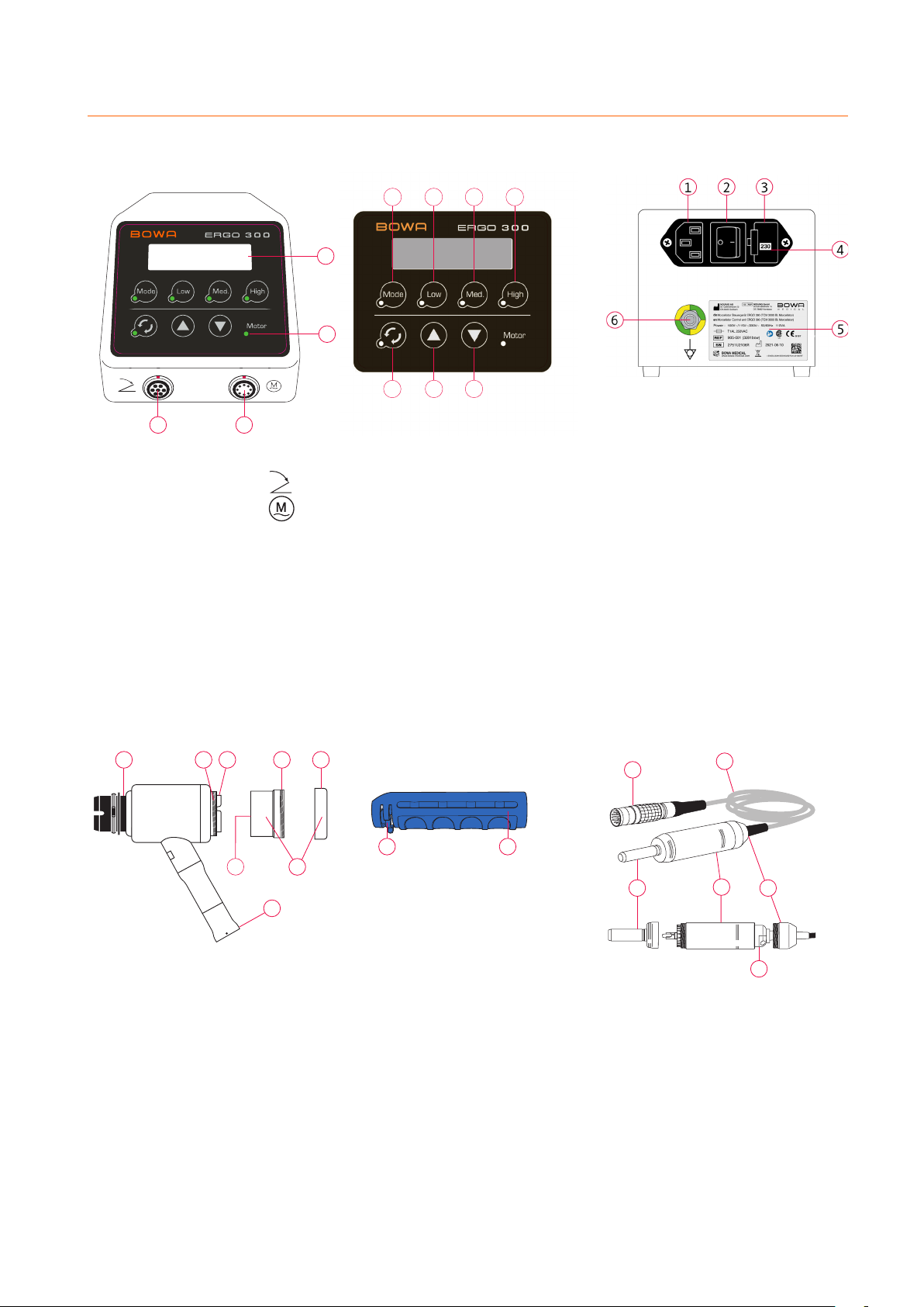
4Device overview
Front view Control panel Rear view
Gear unit Handle Motor
. Display
. Motor LED
. Pedal connection
. Motor connection
. Flange for protective tube con-
nection
. Thread for seal holder
. Cutting tube holder
. Seal unit with membrane screw
. Thread for membrane screw
. Membrane screw
. Seal unit thread
. Motor connection coupling
. Key «Vario» (variable speed range)
. Key «Low» (low speed range)
. Key «Medium» (medium speed range)
. Key «High» (high speed range)
. Key «changing rotation direction»
(When changing the direction of rotation,
the device emits a tone signal.)
. Key «UP» (increase value)
. Key «DOWN» (reduce value)
. Release lever
. Handle
. Mains connection
. Power switch ON/OFF
. Fuse compartment
. Window with indication of
national voltage
. Type plate with type designation,
reference number, serial number,
information on power supply and
device fuse
. Potential equalization
. Device connection plug
. Motor cable
. Motor cap
. Motor
. Handpiece holder
. Motor connection plug

3
1 2
4
1
2
3
4
5
12
1
23
45
7
6
Instructions for use, ERGO - BOWA- IFU-- ERG-S-EN-
Protection sleeve with Obturator
Cutting tube
Trokar sleeve
Grasping forceps
. Protecting sleeve
. Seal unit and Morcellator
attachment
. Valve actuation
. Valve body
. Main body
. Nose for tissue protection
. Cutting edge
. Locking pins
. Protection sleeve
. Locking nut
. Nose for tissue protection
. Obturator
. Mouth insert
. Gripper mouth
. Tube shaft
. Fixed leg
. Flexible leg
. Locking device
. Spring component
Handle

Instructions for use, ERGO - BOWA- IFU-- ERG-S-EN-
4.1 System-Chart, ERGO 300 – Morcellator
Option 1
Option 2
Option 3
Grasping forceps
Grasping forceps
Gear unit
Gear unit
Seal adapter
Seal adapter
Handle
Handle
Myoma drill
Protection sleeve with Ø 12/15 or 20 mm
Protection sleeve with Ø 12 or 15 mm
Protection sleeve with Ø 12 mm
Obturator with Ø 12 or 15 mm
Obturator with Ø 12 or 15 mm
Cutting tube with Ø 12 or 15 mm
Cutting tube with Ø 12 or 15 mm
Cutting tube with Ø 20 mm
Small sealing unit for Ø 12/15 mm
Small sealing unit for Ø 12/15 mm
Small sealing unit for Ø 12/15 mm
Small sealing unit for Ø 12 to 15 mm
Obturator with Ø 20 mm
Large sealing unit Ø 20 mm

Instructions for use, ERGO - BOWA- IFU-- ERG-S-EN-
5 Before use
The ERGO – Morcellator and all required accessories and instruments must be placed on a level nonslip surface. Do
not allow the operating range of the device with cable to be restricted by limiting factors. The display, keypad and indicator
lights must be fully visible at all times.
It is very important to ensure that no objects can fall on the pedal. The power plug at the rear of the device must be acces-
sible at all times.
5.1 Potential equalization connection according to DIN 42801
At the back of the device a potential equalization plug is installed, according to DIN .
The additional potential equalization has the task of equalizing potentials between different parts of conduc-tive materials
that can be touched at the same time, or reducing potential differences.
This connection must be used, to protect the patient, the user and third parties from touch voltages.
The equipotential plug is marked with the following symbol:
5.2 Connection to the power supply
• Before plugging the power cable into the power socket for the first time, you must check the supply voltage setting
next to the power switch.
• In order to prevent the risk of electric shock, the device may only be connected to a power network with a
PE protective earth conductor.
If the voltage shown does not correspond to the local mains voltage, the grey fuse holder must be set to the correct voltage:
. Switch the device off.
. Unplug the power cable.
. Use a screwdriver to open the fuse slot.
. Remove the fuse holder.
. Remove the grey fuse holder and reinsert it so that the local mains voltage setting is shown in the small window.
. Slide the grey fuse holder back in and close the fuse slot.
. Check the mains voltage shown on the fuse slot.
. Plug the power cable back into the device.
5.3 Device preparation
The device is not sterile on delivery. All sterilizable parts must be sterilized before use (see Chapter Instrument prepara-
tion).
If the accessories have already been sterilized: when removing them from the sterile packaging, ensure that the sterile
packaging is not damaged and that the sterility indicator confirms sterility and shelf life of the sterile item has not ex-
pired.
The Morcellator (as per option 1 to option 3) must be assembled under sterile conditions (wear gloves and a mask, place
Morcellator and accessories on a sterile surface).
Instructions for use, ERGO - BOWA- IFU-- ERG-S-EN-
5.3.1 Mounting the morcellator set with protective tube (according to option 1)
There is a risk of injury to tissue by the sharp edge at the distal end of the cutting tube.
• Handle the cutting tube carefully.
• If the cutting tube is not used, rotate the protective tube to the NO CUT position.
• If the cutting tube is not used, it must be placed on a flat, sterile surface so it cannot fall and cause injury
• Check the cutting tube.
• Make sure that the cutting edge of the blade is sharp and undamaged (e.g. no cracks, deformation or burrs).
• Use only cutting tubes in perfect condition.
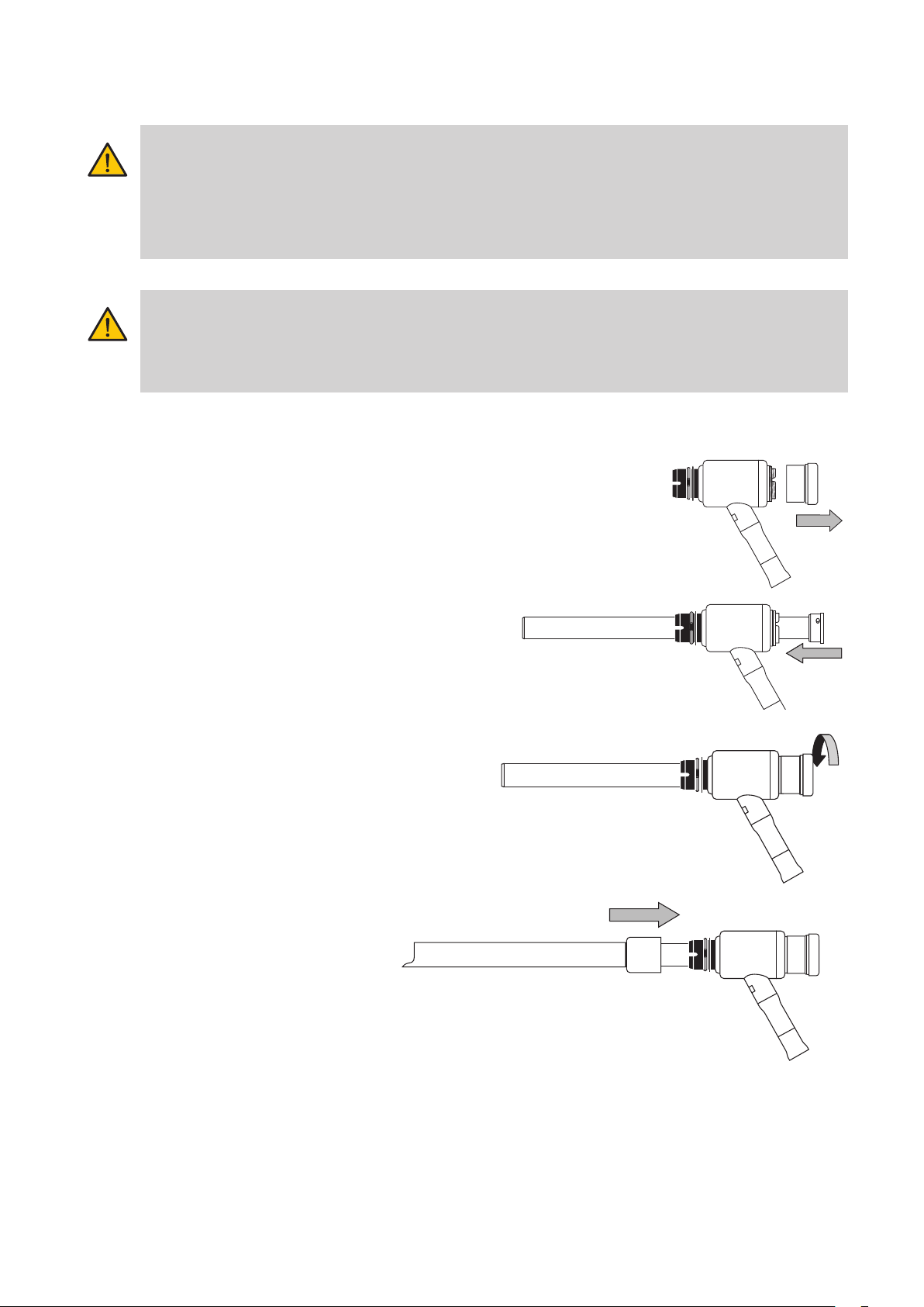
1. Inserting the cutting tube through the gear unit
Remove the seal unit from the gear unit.
Insert the cutting tube through the gear unit. The two
guide pins on the cutting tube must fit into the slot on
the flange of the gear unit.
2. Fixing the cutting tube to the gear unit
Hold the cutting tube with one hand.
Connect the sealing unit to the gear unit with the
bayo-net closure with the other hand.
3. Mounting protective tube
Select a suitable protective tube.
Push the protective tube over the distal end of the cutting
tube. The guide pin of the protective tube must be in the
distal slot of the gear unit.
Lock the protective tube in position with a click.
NO CUT
3
2
14
5
6
6
3
3
2
14
5
6
Instructions for use, ERGO - BOWA- IFU-- ERG-S-EN-
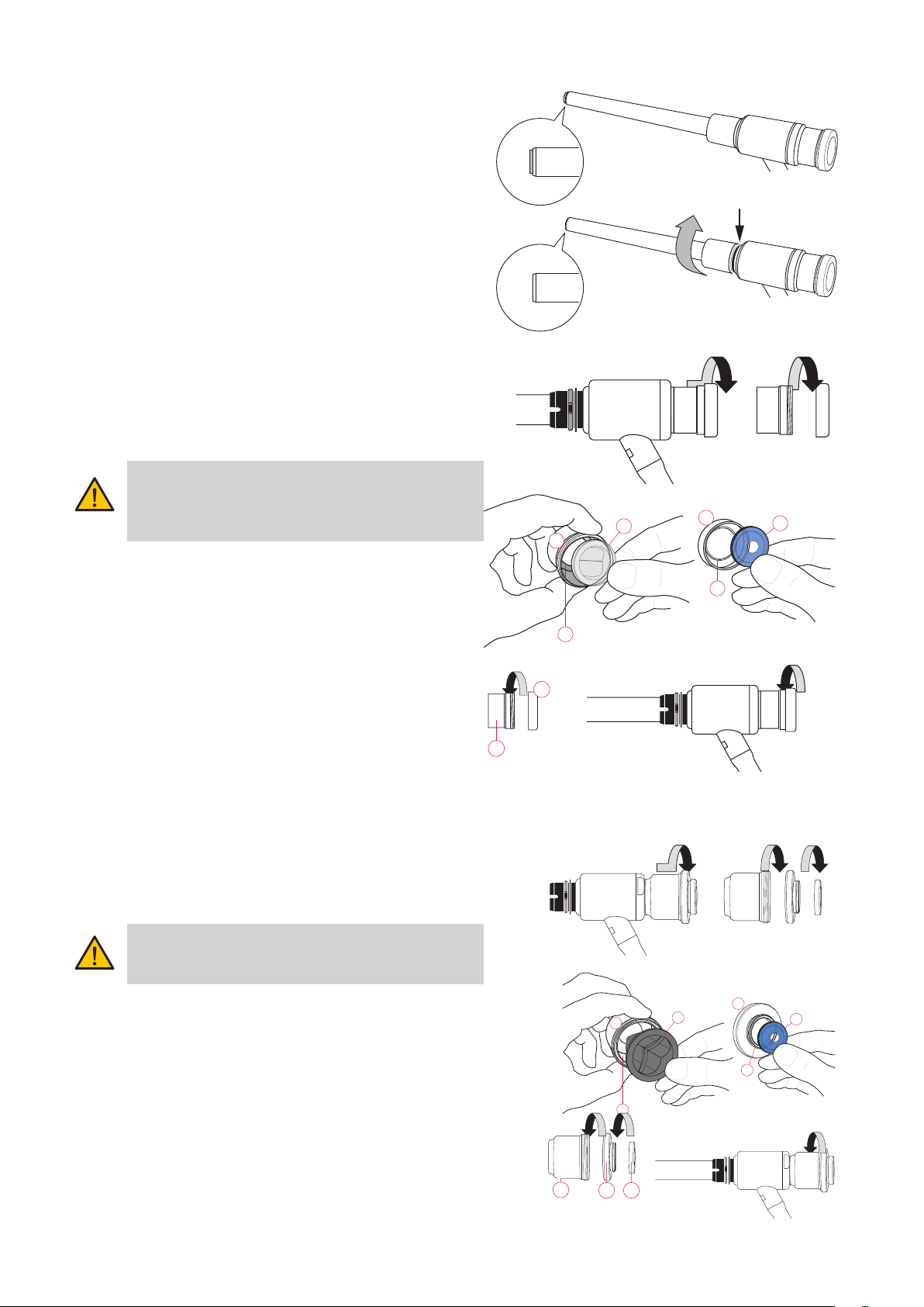
4. Protecting the cutting tube
The distal end of the cutting tube is very sharp.
To prevent injury, the cutting tube must be covered at all
times when it is not in use.
To cover the cutting tube, rotate the protective tube until
the words “NO CUT” are visible in the distal slot of the
gear unit.
The cutting tube is completely covered by the protective
tube.
5a.Replacing the seals of the small sealing unit to use Ø
12/15 mm cutting tubes
Remove the seal unit from the gear unit.
Unscrew the membrane screw from the seal unit.
Check seals before use. Do not use damaged seals (frayed,
discolored, yellowed, porous, no longer elastic).
Position the edge of the roof shaped seal () to point to
the inside stop () of the seal holder () and press the roof
shaped seal in.
Position the edge of the membrane seal () to point to the
slot () of the membrane screw () and press the mem-
brane seal into the slot.
Screw the membrane screw () into the thread of the seal
holder () to the stop and connect the seal unit to the
gear unit.
5b.Replacing the seals of the large sealing unit, for the use of
Ø 20 mm cutting tubes
Unscrew the large sealing unit from the gear unit. Unscrew the
membrane fixing ring from the roof shaped seal fixing ring. Un-
screw the roof shaped seal fixing ring from the seal holder.
Check seals before use. Do not use damaged seals (frayed,
discolored, yellowed, porous, no longer elastic).
Position the edge of the roof shaped seal () to point to the inside
stop () of the seal holder () and press the roof shaped seal in.
Position the edge of the membrane seal () to point to the slot ()
of the membrane screw () and press the membrane seal into the
slot.
Screw the roof-shaped seal fixing ring () all the way onto the
thread of the seal holder () and screw the membrane fixing ring
() onto the roof-shaped seal fixing ring (). Now screw the entire
sealing unit () onto the gear unit ().
2
1
Instructions for use, ERGO - BOWA- IFU-- ERG-S-EN-
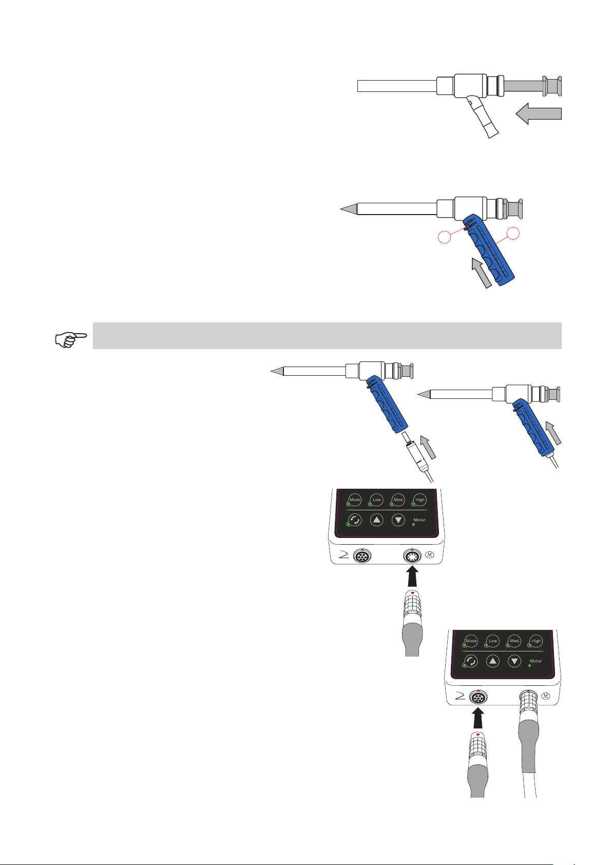
6. Inserting the Obturator
Insert the Obturator through the seal unit, gear unit and
protective tube to the stop.
7. Attaching the handle
Lift and hold the release lever () of the handle ().
Push the handle () over the motor connection of the gear
unit.
Release the handle release lever. The handle release lever
must lock in position.
Do not open the handle release lever to remove the handle during the procedure.
8. Connecting the motor
Insert the motor coupling into the bottom end of the
handle.
Continue to insert the motor until it locks into the gear
unit’s motor connection.
Align the red dot on the device connection plug of the
motor with the red dot on the motor connection of the
control unit.
Plug the motor device connection plug into the motor
connection of the control unit. The plug must lock in
position.
9. Connecting pedal
Align the red dot on the device connection plug of the
pedal with the red dot on the pedal connection of the
control unit.
Plug the pedal device connection plug into the pedal
connection of the control unit.
The plug must lock in position.

Instructions for use, ERGO - BOWA- IFU-- ERG-S-EN-
Functional check
• Check Morcellator for loose parts
• Check that Morcellator is correctly assembled
• Are all labels easily readable?
• Check cutting tube: cutting tube evenly ground, no broken edges or bends?
• Switch on control unit
• Switch on motor (press pedal).
• Run motor with Morcellator for about seconds; it must reach the set speed.
• If it does not run evenly, switch off motor with Morcellator.
• Switch off control unit.
The control unit will only operate if the pedal has been connected to the control unit.
• Check that Morcellator is correctly assembled.
• Check that the gear unit runs smoothly; if necessary treat it with NouvaOil care spray.
• Check that the motor is clean and runs smoothly; if necessary clean it and treat with NouvaOil care spray.
• Repeat the function check.
Risk of injury by motor failure
Problem: the motor becomes very hot. Cause: the motor was damaged during preparation.
Remedy: do not continue to use the motor. Always have a spare motor available.
5.3.2 Assembly of the Morcellator set with Trocar Cannula (according to option 2)
Using the Trocar Cannula
The Trocar Cannula is used instead of the protective tube. The integrated valve flap prevents the escape of gas when
instruments are moved in and out.
The nose of the Trocar Cannula partially extends beyond the cutter tube to protect organs in the abdominal cavity from
the sharp blade. This requires the Morcellator to be rotated under visual supervision (endoscopy) so the nose of the Tro-
car Cannula covers the cutter tube blade to protect the organ.
1. Visual check
• Check the product for sealing, corrosion and sterility.
• Ensure that it is free from rust, dents and scratches.
• The distal end of the Obturator must not be damaged.
• The sealing flap and the seal must not be damaged.
Risk of injury
Select blade. Make sure that the cutting edge of the blade is sharp and undamaged (e.g. no cracks or burrs).

3
2
14
5
6
6
3
Instructions for use, ERGO - BOWA- IFU-- ERG-S-EN-
2. Insert the cutting tube through the gear unit
Remove the seal unit from the gear unit.
Insert the cutting tube through the gear unit. The two
guide pins on the cutting tube must fit into the slot on
the flange of the gear unit.
3. Fixing the cutting tube to the gear unit
Hold the cutting tube with one hand.
With the other hand screw the seal unit onto the gear
unit.
4. Mounting Trocar Cannula
Select a suitable Trocar Cannula. Open the Trocar Cannula
valve by actuating the lever to prevent damage to the
cutting tube by pushing the Trocar too far.
Push the Trocar Cannula over the distal end of the cutting
tube. The guide pin of the Trocar Cannula must be in the
distal slot of the gear unit.
Lock the Trocar Cannula in position with a click.
5. Replacing seals
Remove the seal unit from the gear unit by rotating it
slightly.
Unscrew the membrane screw from the seal unit.
Keep each a roof shaped seal (transparent) and a mem-
brane seal (blue) ready.
6. Position the edge of the roof shaped seal () to point to the
inside contact () of the seal holder () and press the roof
shaped seal in.
Position the edge of the membrane seal () to point to the
slot () of the membrane screw () and press the mem-
brane seal into the slot.
7. Screw the membrane screw () into the thread of the seal
holder () to the stop and connect the seal unit to the gear
unit.
2
1
Instructions for use, ERGO - BOWA- IFU-- ERG-S-EN-
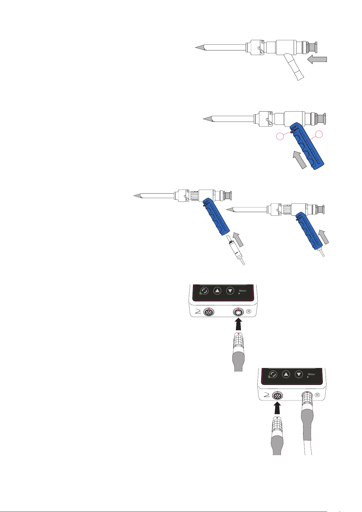
8. Inserting Obturator
Insert the Obturator through the seal unit, gear unit and
Trocar Cannula.
9. Attaching handle
Lift and hold the release lever () of the handle ().
Push the handle () over the motor connection of the gear unit.
Release the handle release lever. The handle release lever must lock in position.
10.Connecting motor
Insert the motor coupling into the bottom end of the
handle.
Continue to insert the motor coupling until it locks into
the gear unit motor connection.
Align the red dot on the device connection plug of the
motor with the red dot on the motor connection of the
control unit.
Plug the motor device connection plug into the motor
connection of the control unit. The plug must lock in
position.
11. Connecting the pedal
Align the red dot on the device connection plug of the
pedal with the red dot on the pedal connection of the
control unit.
Plug the pedal device connection plug into the pedal con-
nection of the control unit. The plug must lock in position.
Other manuals for ERGO 300
1
Table of contents
Other Bowa Medical Equipment manuals


Popular Medical Equipment manuals by other brands


Getinge
Getinge Arjohuntleigh Nimbus 3 Professional Instructions for use

Mettler Electronics
Mettler Electronics Sonicator 730 Maintenance manual

Pressalit Care
Pressalit Care R1100 Mounting instruction

Denas MS
Denas MS DENAS-T operating manual

bort medical
bort medical ActiveColor quick guide

AccuVein
AccuVein AV400 user manual


