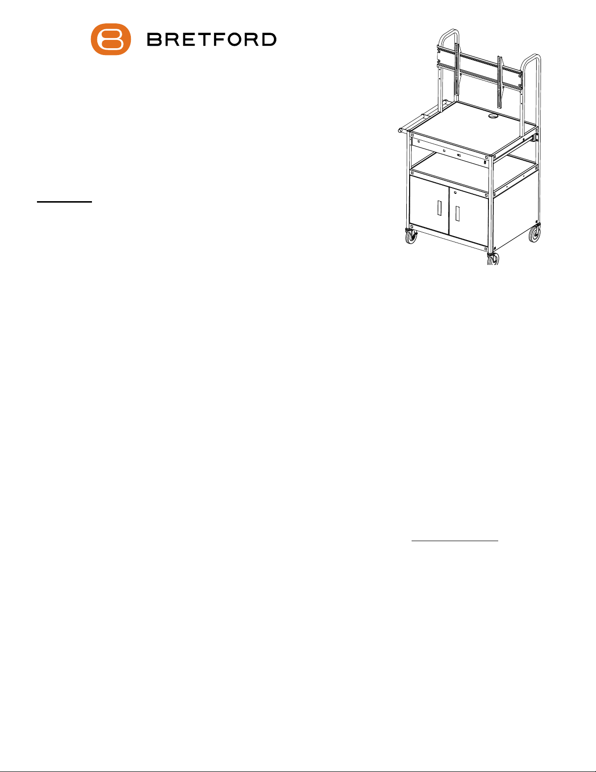
manuals.online logo
Brands
  1. Home
  2. •
  3. Brands
  4. •
  5. Bretford
  6. •
  7. Outdoor Cart
  8. •
  9. Bretford FP42ULC User manual

Bretford FP42ULC User manual

This manual suits for next models

1

Other Bretford Outdoor Cart manuals

Bretford TC12FF User manual

Bretford

Bretford TC12FF User manual

Bretford TC35FF User manual

Bretford

Bretford TC35FF User manual

Bretford Explorer ETCM-SB User manual

Bretford

Bretford Explorer ETCM-SB User manual

Bretford CoreX Series User manual

Bretford

Bretford CoreX Series User manual

Bretford CUBE Toploader User manual

Bretford

Bretford CUBE Toploader User manual

Bretford CUBE Transport Cart 30 User manual

Bretford

Bretford CUBE Transport Cart 30 User manual

Bretford MDMTAB24 User manual

Bretford

Bretford MDMTAB24 User manual

Bretford TC15 User manual

Bretford

Bretford TC15 User manual

Bretford FP42MUL User manual

Bretford

Bretford FP42MUL User manual

Bretford NETBOOK32 User manual

Bretford

Bretford NETBOOK32 User manual

Bretford Basics TC12FF-BK User manual

Bretford

Bretford Basics TC12FF-BK User manual

Bretford TVCA3654 User manual

Bretford

Bretford TVCA3654 User manual

Bretford Explorer User manual

Bretford

Bretford Explorer User manual

Bretford BASICS TC15-BK User manual

Bretford

Bretford BASICS TC15-BK User manual

Bretford TCPUL23 User manual

Bretford

Bretford TCPUL23 User manual

Bretford TC15FF User manual

Bretford

Bretford TC15FF User manual

Bretford TC15SAFF User manual

Bretford

Bretford TC15SAFF User manual

Popular Outdoor Cart manuals by other brands

Gearwrench 83167 user manual

Gearwrench

Gearwrench 83167 user manual

Costway TH10057 manual

Costway

Costway TH10057 manual

Vivo CART-PC02S instruction manual

Vivo

Vivo CART-PC02S instruction manual

Ergotron STYLEVIEW SV42-3162-1 quick reference

Ergotron

Ergotron STYLEVIEW SV42-3162-1 quick reference

VEVOR SC01 quick start guide

VEVOR

VEVOR SC01 quick start guide

Vivo CART-PC01 instruction manual

Vivo

Vivo CART-PC01 instruction manual

Carts Vermont 20 manual

Carts Vermont

Carts Vermont 20 manual

Westward 2CZY4 Operating instructions and parts manual

Westward

Westward 2CZY4 Operating instructions and parts manual

Numatic EcoMatic EM-5 Assembly

Numatic

Numatic EcoMatic EM-5 Assembly

Bosch XL-Cart Operating/safety instructions

Bosch

Bosch XL-Cart Operating/safety instructions

Tennsco Modular Cart Top Component Assembly Assembly Instructions/Parts Manual

Tennsco

Tennsco Modular Cart Top Component Assembly Assembly Instructions/Parts Manual

Clam POLAR TRAILER HD MAX manual

Clam

Clam POLAR TRAILER HD MAX manual

Costway TL0400 user manual

Costway

Costway TL0400 user manual

Trinity 1569839 owner's manual

Trinity

Trinity 1569839 owner's manual

Outsunny 845-340 manual

Outsunny

Outsunny 845-340 manual

XPOtool 30261 user manual

XPOtool

XPOtool 30261 user manual

Westfalia 94 59 66 Original instructions

Westfalia

Westfalia 94 59 66 Original instructions

Gorilla Carts GCR-10P quick start guide

Gorilla Carts

Gorilla Carts GCR-10P quick start guide

manuals.online logo
manuals.online logoBrands
  • About & Mission
  • Contact us
  • Privacy Policy
  • Terms and Conditions

Copyright 2025 Manuals.Online. All Rights Reserved.

FP42ULC FP42MULC
FLAT PANEL CABINET CART WITH
OR WITHOUT A PULL OUT SHELF
1
PARTS LIST
Cart Models: FP42ULC & FP42MULC
Qty Part# Description
1 022-3065 Right Rear Leg Assembly
1 022-3066 Left Rear Leg Assembly
2 022-3067 Front Leg Assemblies
1 010-5778 Top Shelf
1 022-1414 Middle Shelf
1 010-1910 Bottom Shelf
2 010-1908 Cabinet Side Panel
1 010-1909 Cabinet Rear Panel
1 022-1415 Right Door Assembly w/Lock
1 022-1416 Left Door Assembly
1 022-2827 Handle Assembly
1 022-3068 Monitor Bracket
2 010-4953 Hook Bars
2 010-4956 Stop Brackets
2 015-0017 5” Stem Casters w/o Lock
2 015-0018 5” Stem Casters with Lock
Pull Out Shelf Models : FP42MULC
Qty Part# Description
2 010-5783 Shelf Brackets
1 010-5782 Pull Out Shelf
1 030-1468 Left Outer Slide
1 030-1470 Right Outer Slide
2 030-1471 Inner Slides
Electrical Unit Models : FP42ULC-E5BK, FP42MULC-EBK,
Qty Part# Description
1 E6 UNIT 6-Outlet Electrical Unit
HARDWARE LIST
Ref Qty Part# Description
AA 22 030-0300-10T 5/8” Square Head Bolts
BB 24 030-0002 5/16-18 Hex Serrated Nuts
CC 2 030-0023 #6-32 x 3/8” Round Hd Machine Screws
DD 2 030-0024 #6-32 Hex Nuts
EE 4 030-0259 #10 x 1/2” Phillips Pan Hd Screws
FF 12 030-0304 1/4-20 X 1/20” Truss Hd Screws
GG 2 030-1349 5/16-18 x 3/4” Hex Hd Screws
HH 2 SC1048B 1/4-20 x 45mm Bolts
II 2 030-0207 1/4-20 Serrated Flange Nuts
JJ 4 030-0401 5/8-18 x 1 1/2” Hex Head Screws
KK 4 030-0411 5/16-18 Serrated Nuts
LL 4 030-0865 #6 x 1/2” Button Pin-In Hd Screws
MM 2 030-0354 10-32 x 1 1/2” Button Sockets Screws
1 010-1188 Door Stop
2 012-0286 Plastic Handles
1 010-1106 Hex Wrench
1 030-1352 1/8” Security Pin-In Driver Bit
1 030-0368 Replacement Key Set
1 044-2124 Courtesy Hardware Pack
This Pack Consists of:
(4) Metric M4 x 12 Screws
(4) Metric M4 x 30 Screws
(4) Metric M5 x 12 Screws
(4) Metric M5 x 30 Screws
(4) Metric M6 x 12 Screws
(4) Metric M6 x 35 Screws
(8) Small Washers
(20) Large Washers
(4) 5/8” Large Spacers
WARNING: FP42 carts are intended to hold monitors up to 75 lbs. The
use of a TV monitor weighing more than that may result in instability
causing possible injury. The top, middle and bottom shelves are intended to
hold equipment up to 50 lbs. on each shelf. The pull out shelf on FP42MULC is
intended to support equipment up to 15 lbs.
2
BRACKET TO THE INSIDE
AA
These side holes are used for
installing the handle. Leave one of
the sides open to install the handle.
STEP 1
Position the top shelf onto the rear legs making sure the leg brackets are to inside of
the shelf. LOOSELY secure the shelf to the legs using screws (AA) and bolts (BB).
BB
3
Slide on middle shelf.
Slide on bottom shelf.
STEP 2
Slide the middle and bottom shelves onto the rear legs. Slide the front legs on. LOOSELY
install hardware to top shelf corner ONLY, remembering to leave access for the handle.
AA
BB
INSTALL HARDWARE TO TOP
SHELF CORNER ONLY, OMIT
HANDLE SIDE
Slide on front legs.
BB
AA
GG BB
STEP 3
Install handle to either side of the cart using bolts (GG) and nuts (BB).
STEP 4
Secure tube and top shelf together using screws (HH) and nuts (II).
HH
II
4
AA
BB
INSTALL HARDWARE TO
EACH CORNER
BB
AA
STEP 5
Position each side panel under the middle shelf and hook it’s bottom ange under the bottom shelf as
shown. LOOSELY install hardware to each corner with bolts (AA) and nuts (BB). Carefully rotate cart
onto it’s back and install rear panel just like side panels.
Side Panel
Rear Panel
5
NOW TIGHTEN ALL CART CORNER HARDWARE
CC DD
Attach a handle to each door with screws (EE). Then install each door between the middle and bottom
shelves with screws (FF). NOTE: Adjustments to the door stop may need to be done.
EE
STEP 6
Install door stop to bottom shelf using screws (CC) and nuts (DD).
STEP 7
FF
6
7
STEP 8
Push a caster into each leg insert. To ensure casters are securely in place, a rubber mallet may be used
to tap them in place. NOTE: The locking casters MUST be installed on the same side as the handle.
STEP 9
Attach the monitor bracket onto the front of the rear leg tubes as shown using bolts (JJ) and nuts (KK).
JJ KK
8
STEP 10
Attach each shelf bracket under the top shelf as shown using screws (FF).
STEP 11
Install the outer slide onto the shelf bracket by sliding TAB 1 into CUTOUT A and TAB 2 into CUTOUT B.
The pull out shelf should be installed opposite of the handle.
NOTE: Some bend in the bracket is ok as the slides and shelf will take care of that once
they are installed.
TAB 1 TAB 2
CUTOUT A CUTOUT B
This tab determines
where the shelf will
slide out from.
Each cart bracket has
additional cutouts to allow
the shelf to pull out from
either side of the cart.
SKIP TO STEP 15 IF YOUR CART DOES NOT HAVE A SHELF
Make sure the bracket
cutouts face this way, if not
the bracket will be installed
upside down.
FF
9
STEP 12
Install each inner slide into the outer slides. NOTE: Push inner slide in all the way until it snaps in.
Extend the slides to the positioning shown.
STEP 13
10
TAB 1
CUTOUT 1
TAB 2
CUTOUT 2
STEP 14
Install the pull out shelf by sliding CUTOUT 1 into TAB 1 and CUTOUT 2 into TAB 2.