manuals.online logo
Brands
  1. Home
  2. •
  3. Brands
  4. •
  5. Bretford
  6. •
  7. Outdoor Cart
  8. •
  9. Bretford TC35FF User manual

Bretford TC35FF User manual

This manual suits for next models

1

Other Bretford Outdoor Cart manuals

Bretford Explorer User manual

Bretford

Bretford Explorer User manual

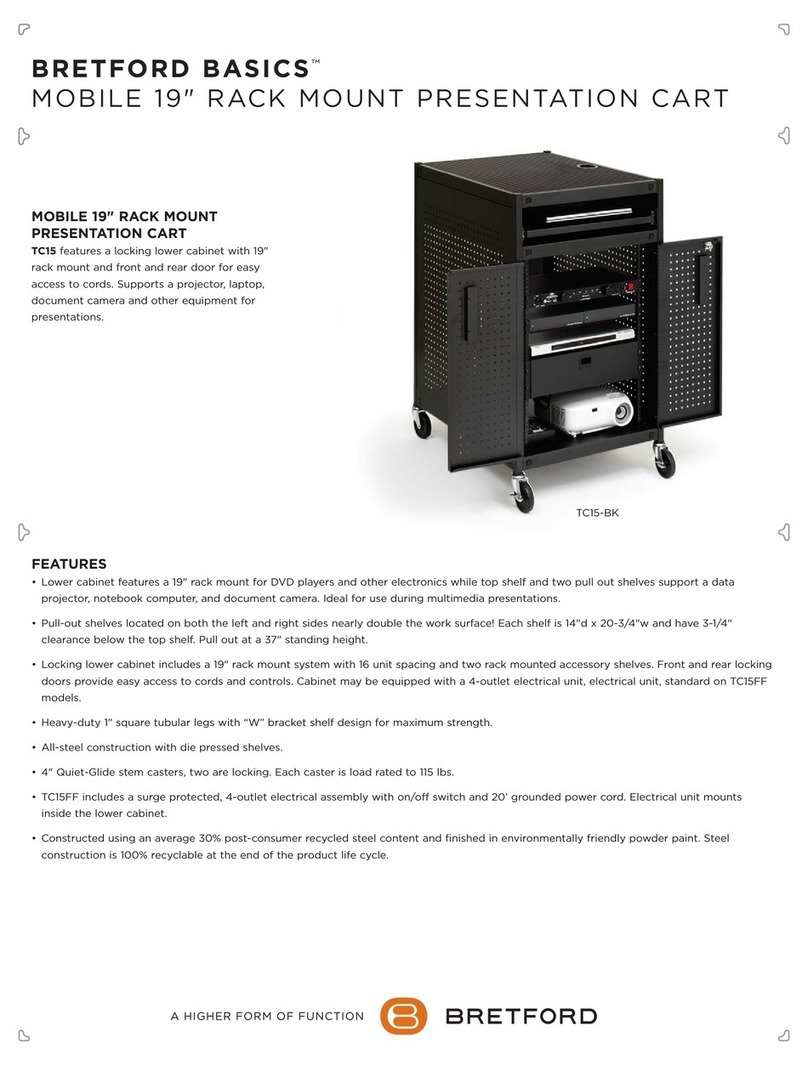
Bretford BASICS TC15-BK User manual

Bretford

Bretford BASICS TC15-BK User manual

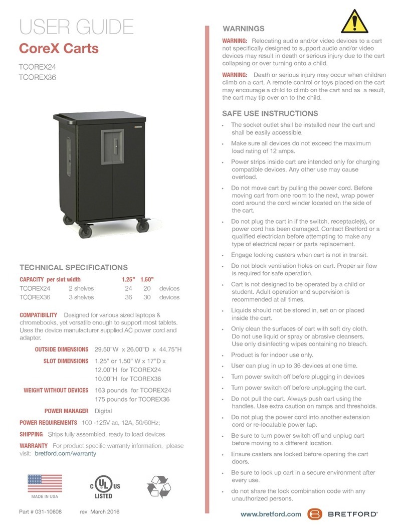
Bretford CoreX Series User manual

Bretford

Bretford CoreX Series User manual

Bretford TC15SAFF User manual

Bretford

Bretford TC15SAFF User manual

Bretford Basics TC12FF-BK User manual

Bretford

Bretford Basics TC12FF-BK User manual

Bretford CUBE Transport Cart 30 User manual

Bretford

Bretford CUBE Transport Cart 30 User manual

Bretford CUBE Toploader User manual

Bretford

Bretford CUBE Toploader User manual

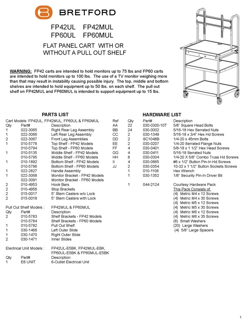
Bretford FP42MUL User manual

Bretford

Bretford FP42MUL User manual

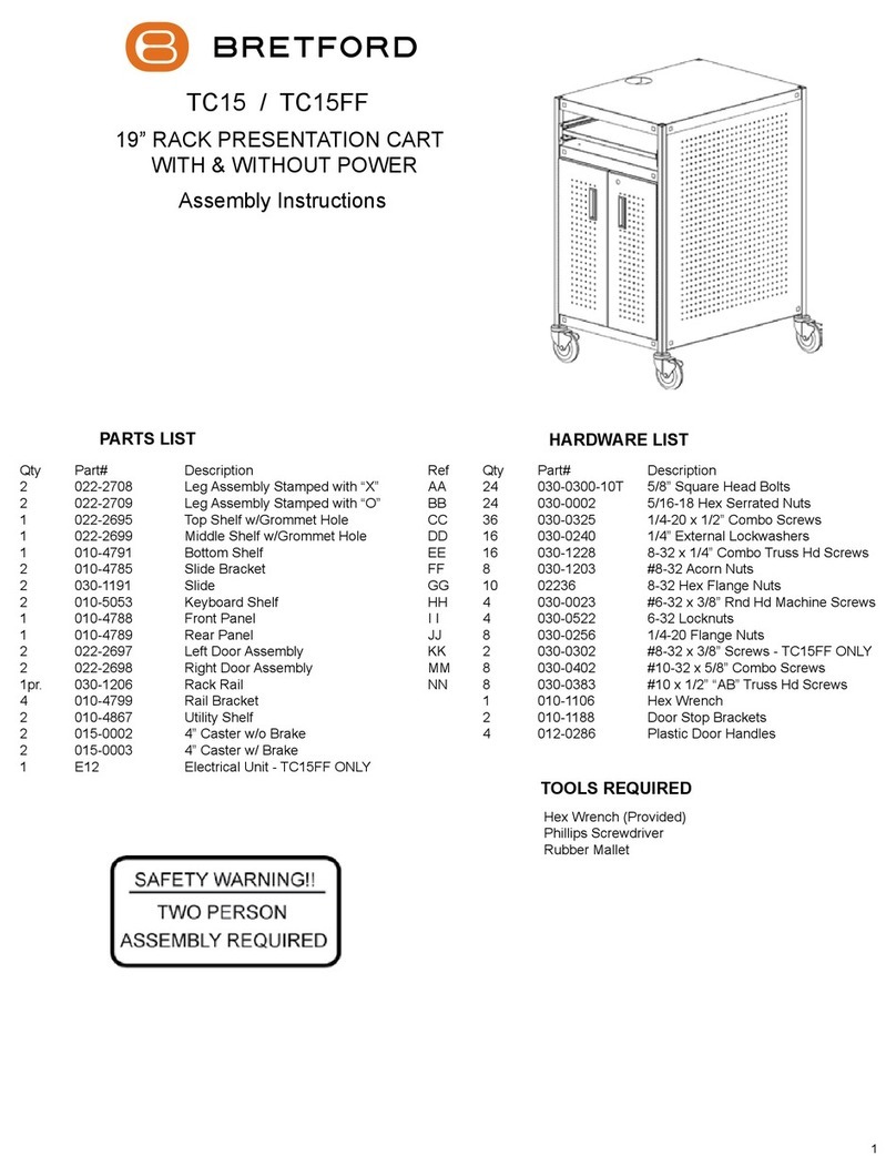
Bretford TC15FF User manual

Bretford

Bretford TC15FF User manual

Bretford TVCA3654 User manual

Bretford

Bretford TVCA3654 User manual

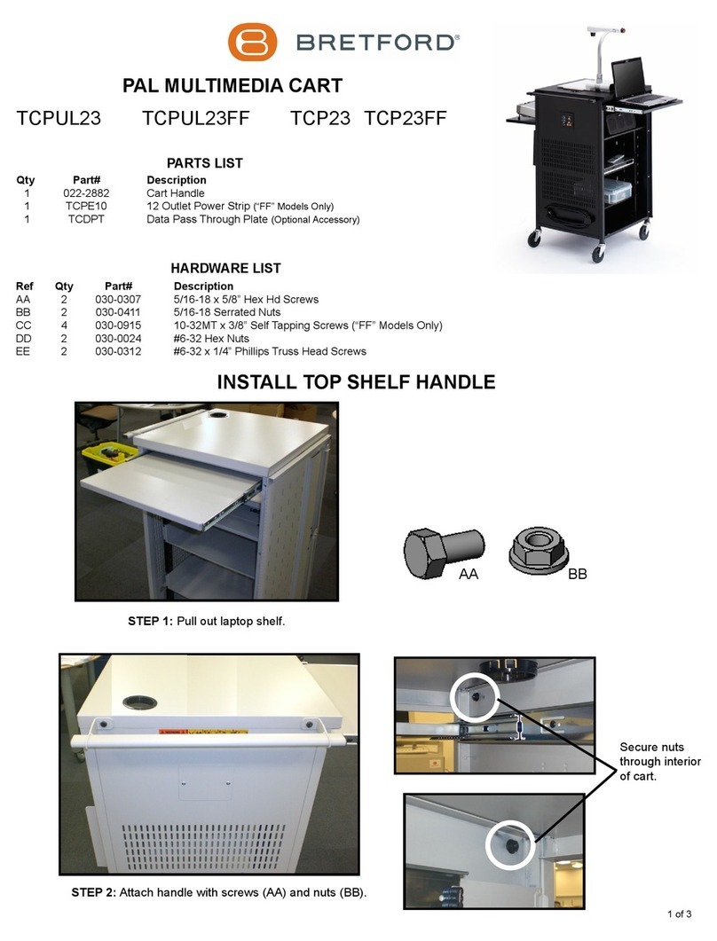
Bretford TCPUL23 User manual

Bretford

Bretford TCPUL23 User manual

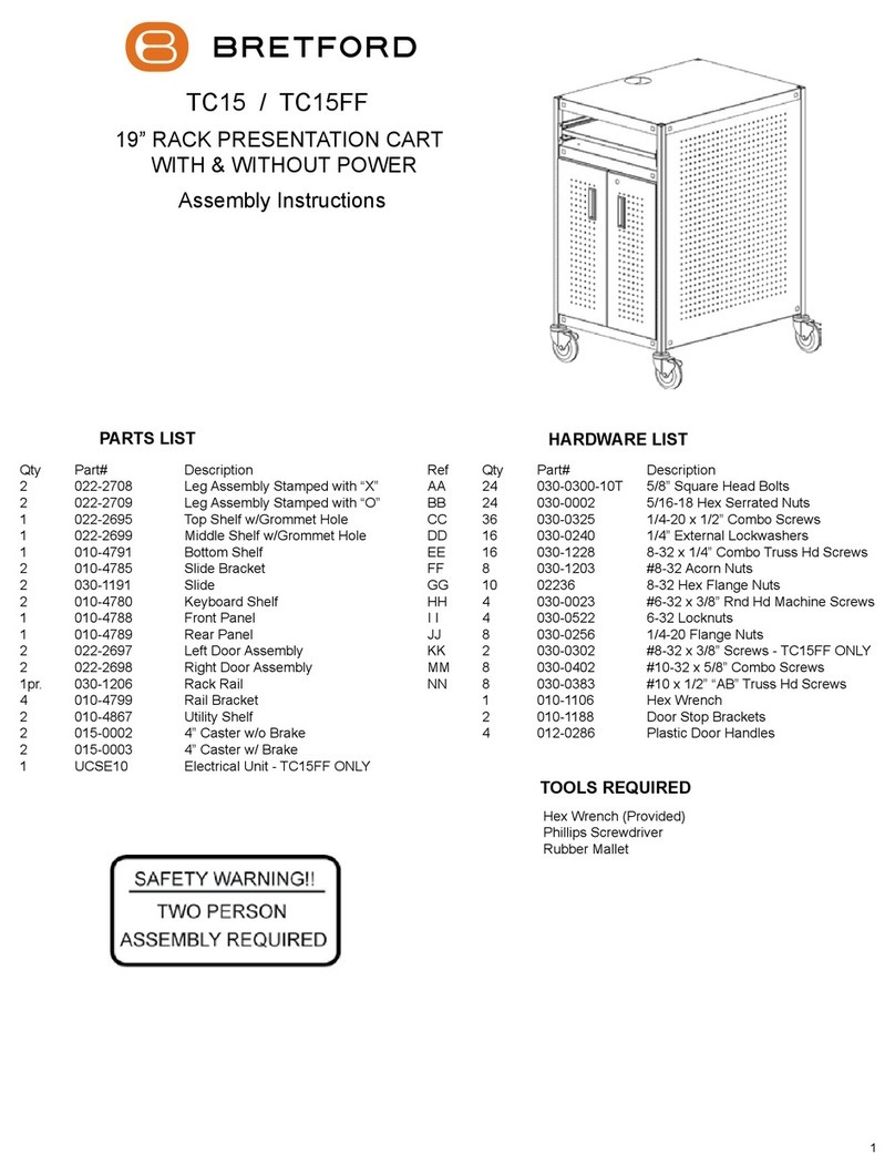
Bretford TC15 User manual

Bretford

Bretford TC15 User manual

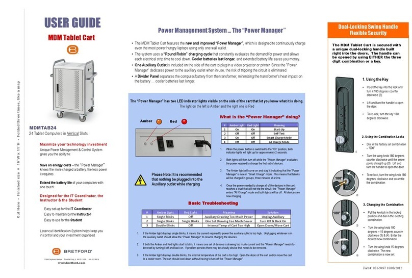
Bretford MDMTAB24 User manual

Bretford

Bretford MDMTAB24 User manual

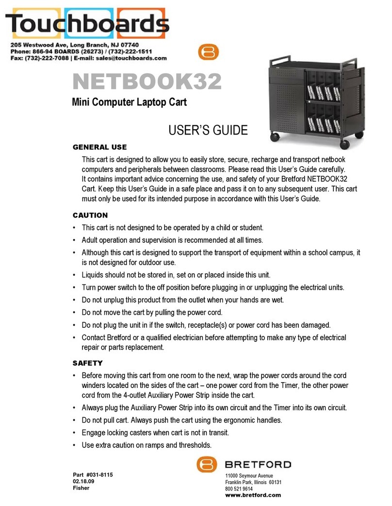
Bretford NETBOOK32 User manual

Bretford

Bretford NETBOOK32 User manual

Bretford Explorer ETCM-SB User manual

Bretford

Bretford Explorer ETCM-SB User manual

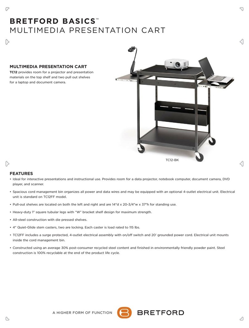
Bretford TC12FF User manual

Bretford

Bretford TC12FF User manual

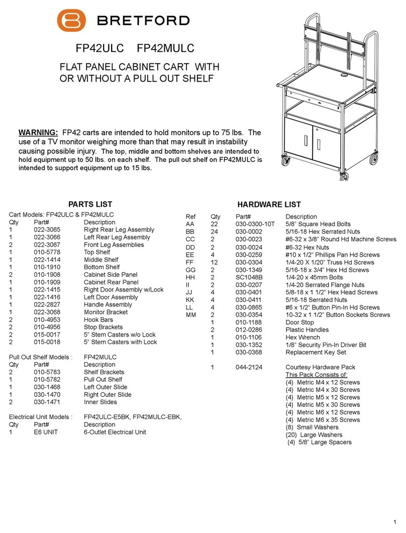
Bretford FP42ULC User manual

Bretford

Bretford FP42ULC User manual

Popular Outdoor Cart manuals by other brands

Gearwrench 83167 user manual

Gearwrench

Gearwrench 83167 user manual

Costway TH10057 manual

Costway

Costway TH10057 manual

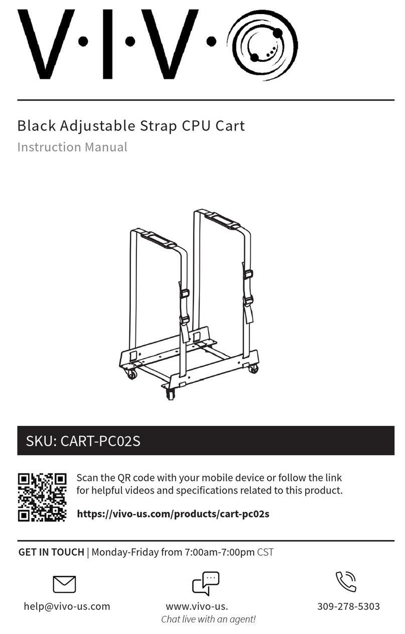
Vivo CART-PC02S instruction manual

Vivo

Vivo CART-PC02S instruction manual

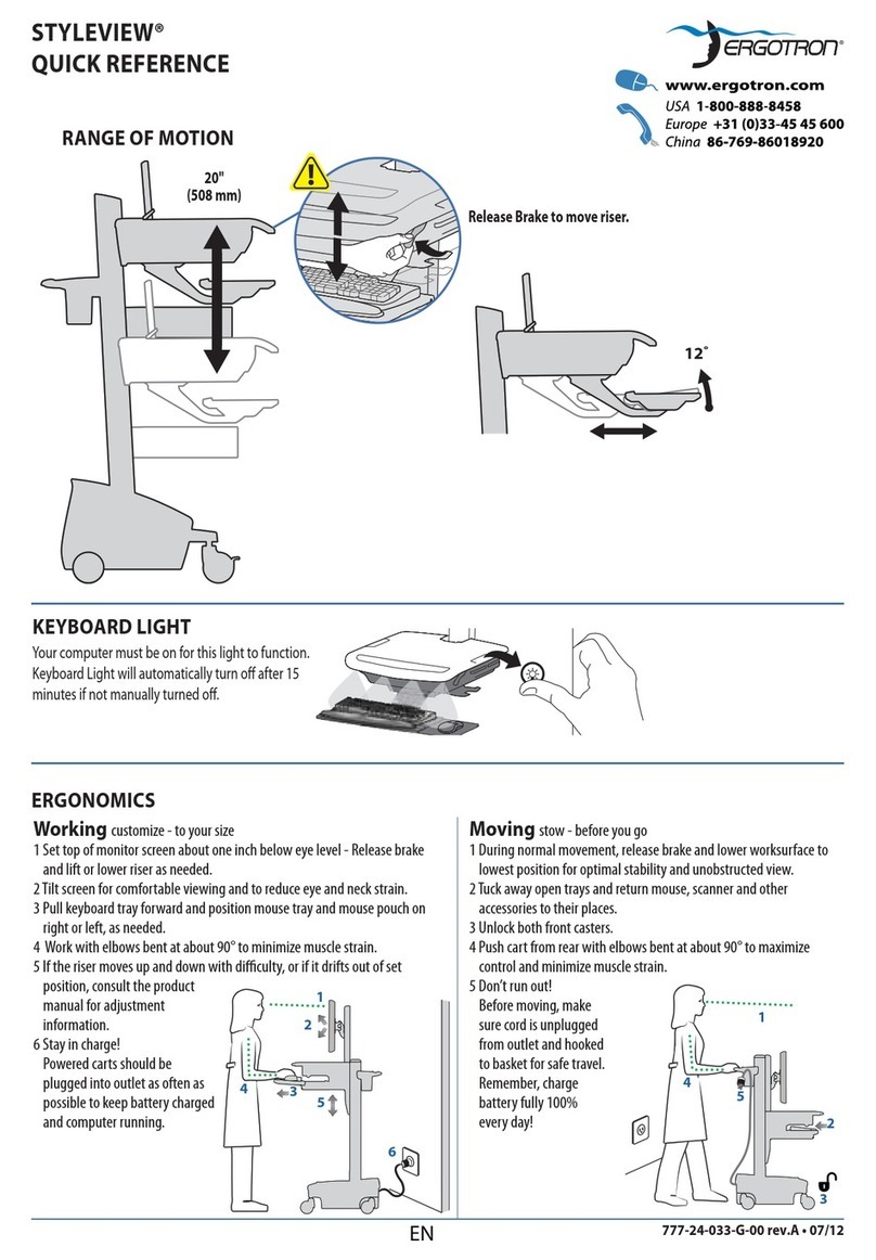
Ergotron STYLEVIEW SV42-3162-1 quick reference

Ergotron

Ergotron STYLEVIEW SV42-3162-1 quick reference

VEVOR SC01 quick start guide

VEVOR

VEVOR SC01 quick start guide

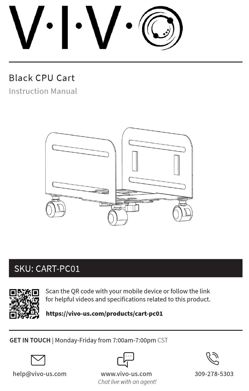
Vivo CART-PC01 instruction manual

Vivo

Vivo CART-PC01 instruction manual

Carts Vermont 20 manual

Carts Vermont

Carts Vermont 20 manual

Westward 2CZY4 Operating instructions and parts manual

Westward

Westward 2CZY4 Operating instructions and parts manual

Numatic EcoMatic EM-5 Assembly

Numatic

Numatic EcoMatic EM-5 Assembly

Bosch XL-Cart Operating/safety instructions

Bosch

Bosch XL-Cart Operating/safety instructions

Tennsco Modular Cart Top Component Assembly Assembly Instructions/Parts Manual

Tennsco

Tennsco Modular Cart Top Component Assembly Assembly Instructions/Parts Manual

Clam POLAR TRAILER HD MAX manual

Clam

Clam POLAR TRAILER HD MAX manual

Costway TL0400 user manual

Costway

Costway TL0400 user manual

Trinity 1569839 owner's manual

Trinity

Trinity 1569839 owner's manual

Outsunny 845-340 manual

Outsunny

Outsunny 845-340 manual

XPOtool 30261 user manual

XPOtool

XPOtool 30261 user manual

Westfalia 94 59 66 Original instructions

Westfalia

Westfalia 94 59 66 Original instructions

Gorilla Carts GCR-10P quick start guide

Gorilla Carts

Gorilla Carts GCR-10P quick start guide

manuals.online logo
manuals.online logoBrands
  • About & Mission
  • Contact us
  • Privacy Policy
  • Terms and Conditions

Copyright 2025 Manuals.Online. All Rights Reserved.

TC35 / TC35FF
HEIGHT ADJUSTABLE PRESENTATION
CART WITH AND WITHOUT POWER
PARTS LIST
Qty Part# Description
2 022-2479 Lower Left Front/Right Rear Legs
2 022-2480 Lower Right Front/Left Rear Legs
1 022-2474 Top Shelf
1 022-2688 Middle Shelf
1 010-4323 Bottom Shelf
2 010-4777 Side Panels
1 010-4778 Rear Panel
1 022-2689 Left Door
1 022-2690 Right Door
4 022-2836 Upper Leg Assemblies
2 010-4780 Keyboard Shelves
2 010-4779 Slide Brackets
2 030-1191 14” Full Extension Slides
2 015-0002 4” Casters w/o Lock
2 015-0003 4” Casters w/ Lock
1 CFPS UNIT Electrical Unit - TC35FF ONLY
HARDWARE LIST
Ref Qty Part# Description
AA 24 030-0300 5/8” Square Head Bolts
BB 24 030-0002 5/16”-18 Serrated Nuts
CC 2 030-0023 #6-32 x 3/8” Machine Screws
DD 2 030-0522 #6-32 Hex Nuts w/ External Teeth
EE 4 030-0383 #10 x 1/2” Truss Head Screws
FF 4 030-0325 1/4-20 x 1/2” Combo Screws
GG 16 030-1228 #8-32 x 1/4” Truss Screws
HH 8 030-1203 #8-32 Acorn Nuts
I I 4 030-0255 #10 x 5/8” Phillips Pan Hd Screws
JJ 10 02236 8-32 Hex Flange Nuts
KK 2 030-0302 8-32 x 3/8” Screws TC35FF ONLY
1 010-1188 Bottom Door Stop
2 012-0286 Plastic Handles
1 010-1106 Hex Wrench
TOOLS REQUIRED
Hex Wrench (Provided)
Phillips Screwdriver
Rubber Mallet (Optional)
Position the lower front legs (stamped “XX” and “YY”) with the brackets facing
up and in as shown in FIGURE 1. Slide the bottom and middle shelves onto the
legs making sure the brackets are inside of the shelves as shown in FIGURE 2.
STEP 1
1
FIGURE 2
FIGURE 1

STEP 2
Slide the 2 remaining lower legs onto
the shelves as shown. Make sure the
brackets are inside the shelves.
Slide the rear panel between the middle and bottom
shelf so that the top ange is behind the leg brackets
and the bottom hooks onto the bottom shelf. Attach in
the 4 corners with bolts (AA) and nuts (BB) as shown.
STEP 3
CAREFULLY turn the unit on its back. Attach each side panel in the same
manner as described in STEP 3 using bolts (AA) and nuts (BB) as shown.
STEP 4
2
AA BB
3
Push casters into the sockets of each leg. To
ensure casters are secure in sockets, a rubber
mallet may be used to tap casters in place.
STEP 5 STEP 6
Attach door stop to bottom shelf using screws (CC)
and nuts (DD). CAREFULLY stand unit upright.
STEP 7 STEP 8
Attach the door handles using screws (EE). Attach the doors (right one has lock) between the middle
and bottom shelves with screws (FF) as shown. NOTE:
Adjustments to the door stop may need to be done.
CC DD
EE FF
4
STEP 9
Separate each slide and attach outer slide piece (2 per bracket) to the
slide brackets using screws (GG) and nuts (HH) as shown. NOTE:
Slide may need to be extended some to align attachment holes.
GG HH
NOTE: Separate slides
by pulling on black tab.
STEP 10
Lay top shelf down and slide upper legs into each corner as shown.
5
STEP 11
Slide each slide bracket down between legs as shown. Secure all 4
corners with screws (AA) and bolts (BB). NOTE: The ange on the
slide bracket is positioned in front of the w-bracket on the leg.
Bracket
Flange
W-Bracket
Top
Shelf
Assembled Position
Upper assembly is height adjustable and
can be mounted in any of these holes.
STEP 12
Slide upper assembly onto lower legs and secure together
with screws (II). NOTE: The upper assembly is adjustable
and can be positioned in any of the lower leg holes.
I I
AA BB
I I
6
GG JJ
Part # 031-7451
Rev. 05.14.08 CZ
Attach inner slide piece to keyboard shelf with screws (GG) and nuts (JJ).
STEP 13
STEP 14
Slide each keyboard shelf into each side of the cart.