Your erfect fit
brink.eu
(NL) “Beste klant,
Dank u voor de aanschaf van dit Brink kwaliteitsproduct.
Het kan zijn dat u in deze handleiding verwijzingen tegen komt in
tekst of beeld naar het merk Thule. Graag willen wij u er op wijzen
dat per oktober 2014 de naam van het bedrijf Thule Towing
Systems B.V. is gewijzigd in Brink Towing Systems B.V. In voorko-
mende gevallen kunt u het merk en bedrijfsnaam ‘Thule’ dan ook
lezen als ‘Brink’. Dank voor uw begrip.
Brink Towing Systems B.V.
(GB) "Dear Customer,
Thank you for purchasing this quality Brink product. It may be the
case that you come across image or textual references in this ma-
nual to the Thule brand. We would like inform you that as of
October 2014, the name of the company Thule Towing Systems
B.V. has been changed to Brink Towing Systems B.V. In future,
you should therefore read any instances of the Thule brand or
company name as Brink. Thank you for your understanding.
Brink Towing Systems B.V.
(D) „Sehr geehrter Kunde, sehr geehrte Kundin,
Vielen Dank, dass Sie sich für dieses Qualitätsprodukt von Brink
entschieden haben. Es ist möglich, dass Sie in diesem Handbuch
Abbildungen oder Angaben finden, die sich auf die Marke Thule
beziehen.
Wir möchten Sie gerne darüber informieren, dass ab Oktober
2014 der Name des nternehmens Thule Towing Systems B.V. in
Brink Towing Systems B.V. geändert wurde. Wenn Sie zukünftig
die Bezeichnung oder Marke Thule sehen, bezieht sich dies auf
Brink. Vielen Dank für Ihr Verständnis.
Brink Towing Systems B.V.
(F) Cher client,
Nous vous remercions d'avoir choisi ce produit Brink. Il est possi-
ble que vous rencontriez la marque Thule au travers des images
ou des références textuelles du présent manuel. Nous souhai-
tons vous informer que depuis octobre 2014, le nom de la société
Thule Towing Systems a été modifié en Brink Towing Systems
B.V. À l'avenir, toute mention faite de la marque ou de la société
Thule devra donc se lire Brink. Nous vous remercions de votre
compréhension.
Brink Towing Systems B.V.
(S) Bästa kund,
Tack för att du köpt denna kvalitetsprodukt från Brink. Det kan
hända att du stöter på bild- eller textreferenser till märket Thule
i den här manualen. Vi skulle vilja informera om att Thule Towing
Systems B.V. från och med oktober 2014 har bytt namn till Brink
Towing Systems B.V. Därmed ska alla förekomster av Thule läsas
som Brink. Vi ber om överseende med detta och tackar för din
förståelse.
Brink Towing Systems B.V.
(DK) "Kære kunde
Tak, fordi du har købt dette kvalitetsprodukt fra Brink. I denne
vejledning vil du muligvis støde på billeder eller tekstmæssige re-
ferencer til varemærket Thule. Vi vil gerne informere dig om, at
navnet på virksomheden Thule Towing Systems B.V. fra og med
oktober 2014 er blevet ændret til Brink Towing Systems B.V.
Fremover skal du derfor læse alle forekomster af Thule-va-
remærket eller firmanavnet som Brink. Tak for din forståelse.
Brink Towing Systems B.V.
(E) "Estimado/a cliente:
Muchas gracias por adquirir este producto Brink de alta calidad.
Es posible que encuentre en este manual referencias textuales o
imágenes relativas a la marca Thule. Nos gustaría informarle de
que, a partir de octubre de 2014, el nombre de la empresa Thule
Towing Systems B.V. ha cambiado a Brink Towing Systems B.V.
Por lo tanto, de aquí en adelante, todas las alusiones a la marca
Thule deben entenderse como referencias a la marca Brink.
Gracias por su comprensión.
Brink Towing Systems B.V.
(I) "Egregio Cliente,
La ringraziamo per aver acquistato questo eccellente prodotto
Brink. È possibile che il presente manuale presenti dei riferimenti
testuali o visivi al marchio Thule. Desideriamo informarLa che dal
mese di ottobre 2014, il nome della società Thule Towing
Systems B.V. è variato in Brink Towing Systems B.V. In futuro per-
tanto tutti i riferimenti al marchio Thule o al nome della società
indicheranno di fatto la società Brink. La ringraziamo per la colla-
borazione.
Brink Towing Systems B.V.
(PL) Szanowny Kliencie!
Dziękujemy za zakup wysokiej jakości produktu firmy Brink. W ni-
niejszej instrukcji mogą się znajdować graficzne lub tekstowe od-
niesienia do marki Thule. Pragniemy poinformować, że od paźd-
ziernika 2014 roku spółka Thule Towing Systems B.V. zmieniła
nazwę na Brink Towing Systems B.V. Dlatego wszelkie wzmianki
o marce Thule teraz odnoszą się do marki Brink. Dziękujemy za
wyrozumiałość.
Brink Towing Systems B.V.
(SF) "Arvoisa asiakas,
Kiitämme laadukkaan Brink-tuotteen hankinnasta. Tässä käyt-
töohjeessa saattaa olla kuvia tai tekstiviitteitä, jotka koskevat
Thule-merkkiä. Haluamme ilmoittaa teille, että lokakuussa 2014
Thule Towing Systems B.V. on muuttanut nimekseen Brink
Towing Systems B.V. Tulevaisuudessa kaikki kaikki viittaukset
Thule-merkkiin muutetaan Brink-merkiksi. Kiitämme ymmärtä-
myksestänne.
Brink Towing Systems B.V.
(CZ) „Vážený zákazníku,
děkujeme Vám, že jste si zakoupil tento kvalitní výrobek značky
Brink.
Možná jste v tomto návodu narazil na obrázek nebo textové od-
kazy se značkou Thule. Chtěli bychom Vás informovat, že od října
2014 byl název společnosti Thule Towing Systems B.V. změněn
na Brink Towing Systems B.V. V budoucnu byste proto měl brát
všechny odkazy na značku nebo název firmy Thule tak, že se jedná
o značku Brink. Děkujeme Vám za Vaše pochopení.
Brink Towing Systems B.V.
(H) Tisztelt Ügyfelünk!
Köszönjük, hogy a Brink minőségi termékét választotta.
Előfordulhat, hogy az útmutatóban található képeken vagy szö-
vegekben a Thule márkára való hivatkozást talál. Tájékoztatjuk,
hogy 2014 októberétől a Thule Towing Systems B.V. vállalat neve
Brink Towing Systems B.V. lett. Ezért, ha a jövőben a Thule
márkára vagy vállalatra való hivatkozást talál, azok a Brinkre vo-
natkoznak. Megértését köszönjük!
Brink Towing Systems B.V.
(RUS) Уважаемый покупатель!
Благодарим Вас за приобретение высококачественного из-
делия Brink. В данном руководстве Вам могут встретиться ил-
люстрации или текст со ссылкой на бренд Thule. Сообщаем
Вам, что с октября 2014 г. компания Thule Towing Systems B.V.
изменила свое название на Brink Towing Systems B.V. В даль-
нейшем все упоминания бренда или названия компании
Thule следует воспринимать как Brink. Спасибо за понима-
ние!
Brink Towing Systems B.V.
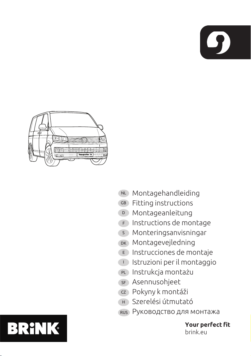
Montagehandleiding
Fitting instructions
Montageanleitung
Instructions de montage
Monteringsanvisningar
Montagevejledning
Instrucciones de montaje
Istruzioni per il montaggio
Instrukcja montażu
Asennusohjeet
Pokyny k montáži
Szerelési útmutat
Руководство для монтажа
NL
GB
D
F
S
DK
E
I
PL
SF
CZ
H
R S
Your erfect fit
brink.eu
Bri k omslag 2015 [disclamer] (9601002)_Bri k omslag 2015 09-02-15 13:55 Pagi a 1