CARRE PENTASEM Series Quick setup guide

Ref. 38011901
Updated 10.11.10
PENTASEM
Assembly - Use
CARRE sas • CONSTRUCTIONS MECANIQUES • Z.A Les Fours • BP 6
85140 SAINT MARTIN DES NOYERS • FRANCE


2
CONTENTS
Page
1
INTRODUCTION................................................................................. 3
2
SPECIFICATIONS .............................................................................. 3
3
SAFETY INSTRUCTIONS .................................................................. 5
3.1 Safety symbols............................................................................................. 5
3.2 Usage as intended....................................................................................... 6
3.3 General safety instructions........................................................................... 6
3.4 Safety in the public domain.......................................................................... 6
3.5 Accident prevention ..................................................................................... 7
3.6 Maintenance and repair ............................................................................... 7
4
OPERATOR CONTROLS................................................................... 8
5
ASSEMBLY AND PUTTING INTO SERVICE..................................... 8
5.1 Link on the tractor........................................................................................ 8
5.2 Mounting the tines........................................................................................ 8
5.3 Positioning the extensions........................................................................... 9
5.4 Equipment....................................................................................................10
5.4.1 Front blade...................................................................................................10
5.4.2 Comb harrow Ø10........................................................................................10
5.4.3 Rubber tyre wheel........................................................................................10
5.4.4 Blower..........................................................................................................11
5.5 Adjusting and using the sower before sowing..............................................12
5.5.1 Markers........................................................................................................12
5.5.2 Pre-emergence markers .............................................................................12
5.5.3 Sowing depth adjustment ............................................................................13
5.5.4 Flow test.......................................................................................................14
5.5.5 Track marker adjustment ............................................................................18
5.5.6 Sower control...............................................................................................19
5.6 Using the sower during work........................................................................20
5.7 Usage after work..........................................................................................21
5.7.1 Emptying the hopper and the dispenser.......................................................21
5.7.2 Sower storage..............................................................................................21
5.8 Using the case
.......................................................................................
22
6
MAINTENANCE.................................................................................. 38
6.1 Maintenance carried out by the user............................................................38
6.2 Maintenance carried out by specialised personnel ......................................38
6.3 Troubleshooting...........................................................................................39
6.4 Tightening torque.........................................................................................40
7
DISPOSAL .......................................................................................... 41
8
CE DECLARATION OF CONFORMITY ............................................. 42

3
1 INTRODUCTION
Before using the PENTASEM sower, we recommend that you read this
manual carefully and that you scrupulously comply with the instructions. As such,
you will avoid putting yourself into a dangerous situation, you will reduce putting into
service time and the risk of undesirable incidents outside the warranty period.
Always keep this manual handy
Your CARRÉ reseller will provide you with advice so that you can obtain full
satisfaction from your machine.
Comply with the safety instructions
Warning symbol
CARRÉ cannot be held liable for any damage and operating incidents occurring
subsequent to usage that does comply with the instructions in this manual.
Warranty: Please fill out the warranty certificate enclosed with the machine
and return it as soon as possible to the indicated address in order to activate
your warranty.
2 SPECIFICATIONS (a)
Description of the PENTASEM
PENTASEM is used for planting a crop in simplified sowing at high speed.
Available in 5 widths, 3m50 as fixed, 4m00, 4m80, 5m60 and 6m00 as foldable.
Planting is accomplished with 45x12 right tines with seed diffuser.
Power required:
From 100 to 150 hp according to the widths.
Operating speed:
Up to 12 Km/h, varies according to method of use.
Static airborne noise:
None of the equipment produces when empty an equivalent A-weighted sound
pressure level exceeding 100 dB at a distance of 1m.

4
Technical characteristics (a):
PENTASEM
Code PTS 3500 PTS 4000 PTS 4800 PTS 5600 PTS 6000
Weight
1045 1670 1735 1790 1840
Specific characteristics
Number of
rows
28 32 32 40 40
Interline
125 mm 125 mm 150 mm 140 mm 150 mm
Working
width (m)
3m50 4m00 4m80 5m60 6m00
Transport
width (m)
3m50 3m20 / 3 parts
3m20 / 3 parts
3m20 / 3 parts
3m20 / 3 parts
Power
required (hp)
100 120 150 150 150
Planting
45x12 right tines with seed diffuser
FRONT EQUIPMENT
FB – FLEXIBOARD front blade
Code
FB35 00 FB40 00 FB48 00 FB56 00 FB60 00
Weight
145 184 198 206 210
REAR EQUIPMENT
HPS – Comb harrow Ø10 on one row with BF link
Code
HPS35 00 HPS40 00 HPS48 00 HPS56 00 HPS60 00
Weight
57 96 100 105 117
BF – Rubber tyre wheel L=50 mm
Code
BF35 00 BF40 00 BF48 00 BF56 00 BF60 00
Weight
140 202 238 246 250
Options (b) (c)
Code
Weight
- Hydraulic blower unit connected to tractor oil intake (for tractor
without flow adjustment)
- 300 litre hopper side board
- Distribution head cover 40/20
- Distribution head cover 32/16
- Descent seal cap
- Single disc pre-emergence marker
- Dual disc pre-emergence marker
- Electric track marker valve
- Set of 4 stands
-
Pair of fixed pneumatic depth gauge wheels on extensions
11916
11911
VN90048027
VN90048025
119005
11955
11954
VN90050044
11702
11925
18
17
5.3
2.8
-
30
60
0.5
30
130
(a) The technical characteristics, dimensions and weights are provided for the purposes of
information; these may change.
(b) Incomplete list.
(c) Regardless of the width of the device.

5
3 SAFETY INSTRUCTIONS
3.1 Safety symbols
On the machine
Make sure that the warnings and pictograms remain clean and visible at all times. If they
become deteriorated, ask your manufacturer (or distributor) for new stickers.
If repair work is done, ensure that the spare parts have the same stickers as the original
parts.
²
Triangle indicating DANGER each time that the risk of an accident is high or when
the equipment may be damaged.
This arrow indicates areas where advice is provided on facilitating the work.
Read the maintenance
booklet and the safety
instructions before
turning on the
machine.
Before any
intervention, turn off
the tractor engine and
remove the key.
In order to prevent leaks
in the hydraulic circuit,
follow the instructions in
the maintenance booklet
Have everyone
leave the
dangerous area.
There is a risk
of crushing
Never place
hands in the
danger areas
when the parts
are in motion,
there is a risk of
pinching.
Have everyone
leave the
dangerous area.
There is a risk
of crushing
Keep the
sower's drive
belt protective
cover in place
in order to
protect the
hands
Do not step
on the
footstep while
the machine
is moving
Electrical
installation

6
3.2 Usage as intended
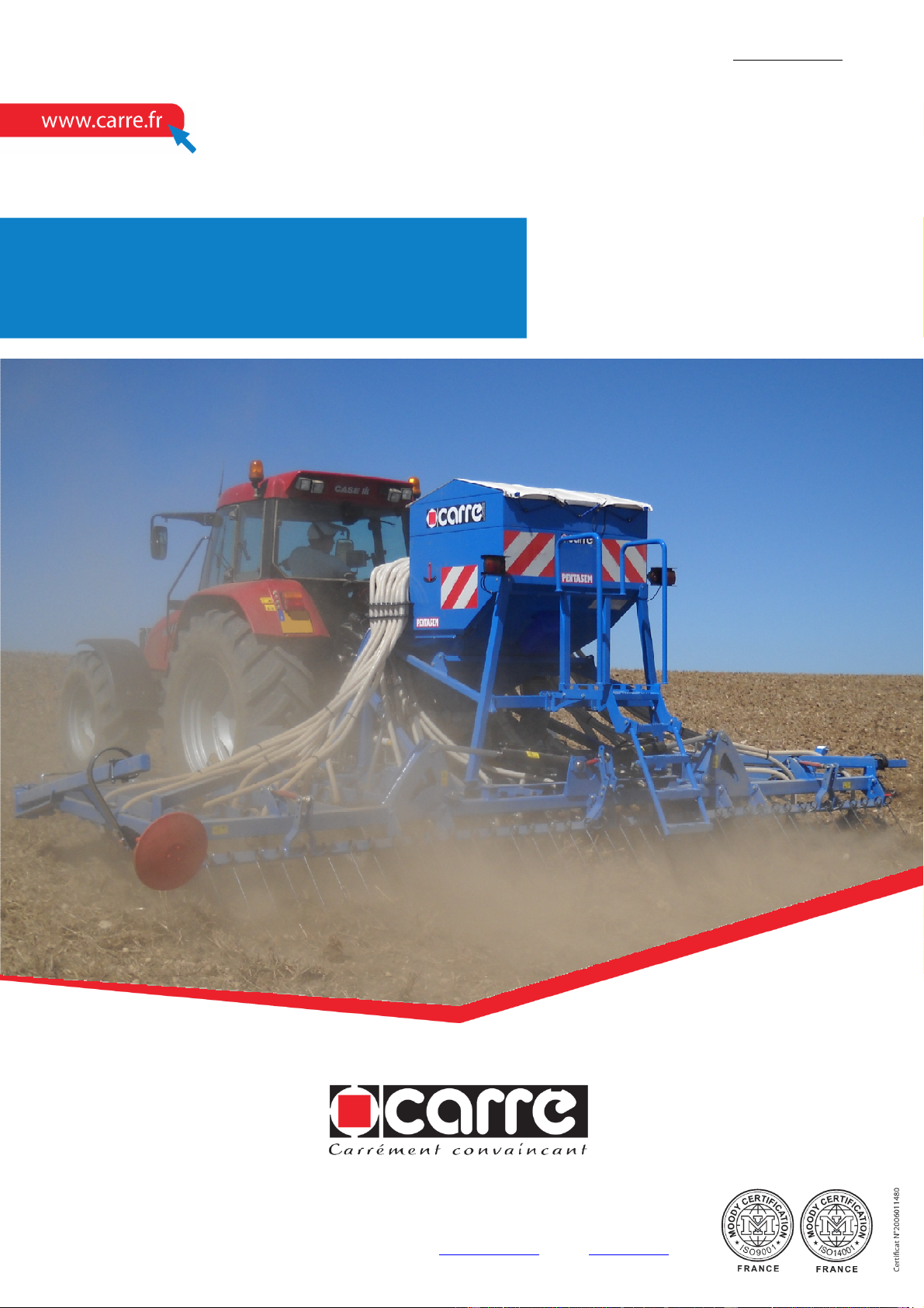
PENTASEM is designed to be used for planting a crop in simplified sowing at high speed.
Any use other than the latter shall be considered as non-compliant with the intended use
and shall release the manufacturer from any liability in the event of prejudice; the user
alone shall incur the risks that result from such use.
Comply with all of the installation, operating, adjusting, maintenance and repair instructions
contained in this notice.
Use only spare parts and accessories that comply with the manufacturer's
recommendations.
The use, maintenance and overhauling of the PENTASEM must be entrusted only to
people who are familiar with and who are informed of the possible dangers.
Do not modify or have your machine and its accessories modified by another person
(mechanical, electrical, hydraulic, pneumatic characteristics), without first obtaining
approval from your manufacturer.
Not complying with these rules can make your machine dangerous. In the event of damage
or injury, the manufacturer shall be released from any liability.
Moreover, the special instructions concerning the prevention of accidents must be complied
with, as well as the general rules in terms of technical safety, occupational medicine and
legislation concerning the use of roads.
The manufacturer declines all liability in the event of prejudice resulting from a modification
made to the PENTASEM without its approval.
3.3 General safety instructions
Only use the PENTASEM if all of the protective and safety devices are installed and are
operating correctly.
Check that the screws are tight on a regular basis and tighten them if necessary, especially
the clamping screws for the tines and the bearings on the equipment.
In the event of operating incidents, stop the machine immediately, then repair the
breakdown or have it repaired immediately.
3.4 Safety in the public domain
Before driving on a road, you must become familiar with the operation of all of the controls.
Comply with the rules of the road when you move into the public domain (roads, paths and
squares). Make sure beforehand that the condition of the PENTASEM is compliant with the
regulations set forth in the rules of the road.
Comply with authorised transport width limitations.
Adjust your speed and driving style to the land, roads and paths. Remain vigilant and
cautious!
At all times and in particular on sloped and broken land, operate the machine at slow
speed, especially when turning and do not change direction abruptly.
Do not brake or start abruptly while going up or down a slope.
Driving is influenced by the machine coupled to the tractor. Comply with the axle load limit
and the gross weight so that steering and braking precision are maintained and, when
turning, give particular attention to the overhang and the inertia mass of the PENTASEM.
Do not transport anyone on the PENTASEM.

7
3.5 Accident prevention
In addition to the recommendation in this manual, follow the instructions of the farming
mutual insurance companies.
During the hitching of the PENTASEM to the tractor:
- Ensure that the PENTASEM is resting on stable ground.
-Never remain between the tractor and the PENTASEM; there is a risk of an accident.
-Operate the 3-point hydraulic lift system slowly and with caution.
-Check that the 3-point hitching categories of the tractor and of the PENTASEM
correspond.
During use:
- Before turning on the machine, ensure that no one is within the vicinity of the machine.
Ensure that there is sufficient visibility.
- Do not transport anyone on the hoeing machine during work.
- None of the protective devices prescribed and delivered with the machine are to be
removed.
- Make sure that no one is in the pivoting area of the extensions that can be folded, the
markers and any pre-emergence markers.
- While operating and when in motion, the PENTASEM causes the projection of soil and
stones. Ensure that no one is within the vicinity of the machine.
During the operation of the power take-off of the sower:
-Comply with the instructions in the U-joint transmission manual.
- Use only U-joint transmission with their regulatory protectors (the tube and cone must
be mounted).
- Mount the U-joint transmission shaft only if the motor of the tractor is stopped and if the
power take-off is disconnected.
- Comply with the overlapping prescribed for the sliding shafts in transport and working
position.
- The U-joint transmission protectors must be immobilised in rotation.
- Do not turn on the power take-off until there is no one within in the vicinity of the sower.
- The rotating speed of the tractor's power take-off must correspond to the authorised
rotating speed of the sower.
- WARNING: Due to its inertia, the power take-off continues to rotate after it has been
disconnected. Stay away from the device during this lapse of time and do not intervene
on the latter until it has come to a complete stop.
- Put the protective sleeve back on tractor's power take-off, as soon as the U-joint shaft is
no longer connected to it.
3.6 Maintenance and repair
- Comply with the time frames that are recommended or indicated in this manual when
carrying out scheduled inspections and verifications.
- Before beginning any maintenance or repair work, make sure that the hydraulic
installation is not under pressure, and stop the tractor's power take-off and motor.
Uncouple the PENTASEM from the tractor.
- Carry out maintenance or repair work only if the PENTASEM is resting flat on stable
ground and where there is no risk of tipping.
- Do not carry out any maintenance work on a raised device without having installed the
appropriate supports for safety reasons.

8
- When assembling and disassembling, use appropriate means that do not compromise
your safety.
- Take advantage when cleaning the PENTASEM at the end of each crop year at least,
to check that the hydraulic lines are properly sealed, the connections are tight and that
there are no defects caused by friction. Replace anything that is deteriorated
immediately.
- When replacing wearing parts, use suitable tools and wear gloves.
- Spare parts must meet the manufacturer's technical requirements, which is always the
case with original parts.
- Before carrying out any electrical welding work on the PENTASEM, when it is hitched to
the tractor, disconnect the battery cables.
4 OPERATOR CONTROLS
With regards to hitching, and for safety reasons, the original pins must be used. In
order to prevent loss, the pins as well as their lynch pins are connected to the PENTASEM
by a chain.
5 ASSEMBLY AND PUTTING INTO SERVICE
5.1 Link on the tractor
The PENTASEM is equipped with a 3-point pin coupling between yoke No. 3 and
reversible pin diameter No. 2 and No. 3, in accordance with standard NF U 14032.
WARNING: Never remain between the tractor and the PENTASEM; there is a risk
of an accident.
The "Tractor + PENTASEM" unit has a substantial mass. In order to allow for
sufficient static stability, the load of the front axle of the tractor must not be less
than 20% of the empty weight of the tractor. For this, the most practical method consists in
weight the front of the tractor on a scale and comparing the result with the recommended
value in the tractor's user manual. Add weight to the front of the tractor if necessary.
5.2 Mounting the tines
Planting seeds is accomplished with a 45x12 right tine with diffuser.
The tine pitch depends on the PENTASEM model (125 mm pitch for the 3m50 and
4m00 model; 140 mm pitch for the 5m60 et 150 mm pitch for the 4m80 and the 6m00).

9
5.3 Positioning the extensions
The extensions can be in a fixed position or in a floating position. The floating position is
used to follow the differences in level of the ground in order to obtain even sowing in liaison
with the optional wheels on the extensions.
The PENTASEM must be placed on flat ground in unfolded position when switching from
the fixed position to the floating position. Remove the pin from the swivel cylinder of the
extensions and direct the shims (see drawing below).
Give attention to the adjusting of the lower stop according to the desired position of
the extensions.
Never switch from the floating or fixed position with the machine folded
Positioning the shims
Adjust the step screw in contact with
the extension in horizontal position
Retract the step screw to the maximum for
the oscillation of the extension

10
5.4 Equipment
5.4.1 FLEXIBOARD front blade
The front blade is mounted on the front beam of the PENTASEM. It is provided with several
spring blades, and participates in levelling the ground before the sowing tine passes.
Adjustments are made by the push bars and can be turned off.
5.4.2 Comb harrow Ø10
The comb harrow is mounted behind the sowing tines, and allows the sowing to be finished
by closing up the furrows evenly.
It is used alone or along with the rubber tyre wheels.
5.4.3 Rubber tyre wheel
The rubber tyre wheels are mounted behind the sowing tines. They allow for regular and
individual consolidation of the sowing coulter.
Blade adjustment
Harrow
inclination
setting
Harrow height
setting
Comb harrow alone Comb harrow + rubber tyre wheel
Harrow height
setting
Harrow
inclination
setting
Comb harrow + rubber tyre wheelRubber tyre wheel alone
Depth
adjustment Depth
adjustment

11
5.4.4 Blower
Mechanical blower
Required nominal speed is 1000 rpm PTO which is a blower rotation of 4300 rpm.
At the end of the plot, reduce the PTO to a minimum in order to avoid a power loss
in blower speed.
Hydraulic blower
Hydraulic supply to be connected as single-acting of the tractor.
Connect the return to the free return of the tractor, with pressure less than 5 bars,
otherwise the shaft seal will be destroyed.
Oil flow: 40l/min which is a blower rotation of 4300 rpm.

12
5.5 Adjusting and using the sower before sowing
5.5.1 Markers
Adjusting the markers
Disc markers can be adjusted in the middle of the tractor. They mark a line on the
ground to follow during the return. The middle of the tractor as such passes along
this line on the ground
The marker disc is adjusted on the ground;
measure the distance X between the
middle of the last tine and the middle of
the disc (see the table according to the
width of the sower).
Adjusting marker inclination
The inclination is adjusted using 2 adjusting
screws. It can be placed in a fixed position
or in a floating position.
The marker sequence is done at the end of the field using the control of a single dual-
action distributor.
5.5.2 Pre-emergence markers
The single- or dual-disc pre-
emergence markers are lowered
simultaneously with the track
marker valve control in order to
create lines for the treatment
machines.
They are activated at the same
time as the track marker valves of
the sprayer track.
Sower
width
X (cm)
4m00 206.2
4m80 247.5
5m60 287
6m00 307.5
X
Adjusting screw

13
5.5.3 Sowing depth adjustment
Depth gauge wheel on fixed chassis.
The depth adjustment wheels allow the working depth to be controlled reliably.
Adjusting the depth is carried out
using the crank screw.
The wheels must be set
identically on each side of the
sower.
Depth gauge wheel on extensions
The depth gauge wheels on the extensions allows the working depth to be controlled when
the extensions are in floating position, in order to follow the differences in level of the land.
Depth adjustment is carried out using 2 pins
Position of the pin
if work as
floating
Lower
stop
Upper
stop

14
5.5.4 Flow test
Determining the setting value
For a correct adjustment, it must be determined whether you are dealing with a common
seed or fine seeds.
-
Common seed: between 4 and 10 mm
-Fine seed: between 1.5 and 4 mm
Following the handling instructions in the order listed and the adjustment table in order
to control the flow. Use the microdosage for sowing fine seeds and small quantities.
Distribution + blower details
1- Case
2- Graduation sector
3- Inverter
4- Drain trapdoor
5- Threaded rod
6- Microdosage sprocket
7- Gear reducer
8- Elbow
9- Spring clamp for the blower air adjustment flap
Table of settings
The values shown in this table of settings are provided solely for the purposes of
information, as the specific weight and the calibre of the seed are often very different. The
correct value is determined by carrying out a flow inspection at a fixed station. The volume
determined as such will always correspond the the seed flow (for the same seed).
1
2
3
4
5
6
9
8
7

15
TYPES OF SEED
Common seed
(seed value between 4 and 10mm)
*:
In case of a low flow (for example: cell width < 25mm) more regular sowing may possibly be obtained by activating micro dosage even in a normal sowing range
Fine seed
(seed value between 1.5 and 4mm
)

16
During the fixed station flow inspection, proceed as follows:
1- Do you want to perform a flow control for common seed or with fine seed?
2- Types of seed
a-
For common seed, place the inverter C on the dispenser and the spring clamp of the
blower adjustment flap to open position [ 1 ] (in the axis of the pipe) and place
sprocket A in sprocket B.
b- Adjust smaller doses only if the dispenser is running or if the hopper is empty.
Otherwise, you run the risk of deteriorating the dispenser by pressing on the seed.
For fine seed, turn the threaded rod until the value 0 is shown in the graduated
sector. Then turn the inverter C to the right, until it snaps into the groove of the hex
shaft.
Also position the spring clamp of the blower air adjustment flap to position [ 2 ] and
take out sprocket A so that it drives sprocket C.
3- Use the settings table to locate the value that corresponds to the quantity to sow.
4- The graduated sector indicates values from 0 to 110 (only up to 25 for small seeds).
Turn the threaded rod until the value of the setting appears against the notch of the
case.
A
B
A
C
B
1
2
C
2

17
5- Close the drain trapdoor
6- Pour the seed into the hopper
7- Remove the elbow located under the injector after loosening the wing nut
8- Place the basin (fixed under the hopper) under the opening of the injector to collect
the seed from the flow test.
9- Perform the weighings (see procedure on page 30).
10-Then attach the elbow between the injector and the blower.
The flow inspection test is complete.
Flow test with microdosage.
With microdosage, it is possible to sow small seeds and very small quantities per hectare.
The advantage with microdosing compared to a normal rotating speed for small seeds
resides in the fact that the opening of the cells is twice as large for the same flow. This
results is better self-cleaning of the cells.
Pull the red sprocket towards the exterior until it snaps in. The microdosage is connected.
The value of the setting must be read from the table for small seeds.
A cell cleaning brush, for sowing small seeds, is fixed to the inside of the case of the
dispenser. This prevents the grooves from becoming clogged when treated seed is used,
for example. It is located under the steel sheet that covers the injector behind the
sprockets. Check that it is in good condition before beginning to sow.
For common seed, remove the brush

18
5.5.5 Track marker adjustment
Passage marks can be marked out automatically with the device that electronically shuts
off ploughshare power.
In order to mark out the lines, ploughshare power must be cut off by closing the
corresponding electric valves. The track of the tractor that will be used later for spreading
fertiliser or for spraying is determinant in choosing the ploughshares that have to be closed.
The power must be cut off for several ploughshares located next to each other (2 on the
right and 2 on the left as standard, with a possibility of 3 on the right and 3 on the left for
wider wheels).
A rate determine the moment when the track marking operation is carried out.
Working width of the treatment machine
--------------------------------------------------------------- = Track marking rate
Sower working width
Example: With a 4m80 sower and a sprayer with a working width of 24m:
24
---- = 5 = Track marking rate
4.8
The following table shows the most common combinations for marking out lines.
Sower
Sprayer (M)
8 9 12 15 18 20 21 24 27 28 30 32 33 36 38 40 42
4m00 2 3 5 6 7 8 9 10
4m80 5
5m60 5
6m00 2 3 4 5 6 8
The even rates are for tracking marking with two passes. Lines for passes that are marked
out in a single pass are however more accurate than in they are marked out in two passes.
For this reason, lines can also be marked out in a single pass by using the even rates.
Cleaning brush

19
In this case, sowing must be carried out during the first pass with only half the working
width of the sower, or distribution must be disconnected for the corresponding portion of
the sprayer or fertiliser distributor.
The odd rates (i.e. 3, 5, 7, etc.) mark out lines in a single pass.
Before using for the first time, check that the lines are marked out with a spacing
that complies with what you are looking for! The sowing tines in the line must not
leave seed.
5.5.6 Sower control
Before leaving the farm to go to the place of use, you are advised to check the following:
•The sower is compliant with the instructions concerning transport on roads.
•The hitching of the sower to the tractor.
•The setting of the track marking (rate)
•The opening and closing of the electric valves by the track marking device.
•The track marking and the electronic control of the sower when changing tractors.
•All of the sowing tines sow. (Turn on the blower and allow the distribution to operate,
by passing in front of the radar, seed should then be on the ground under each tine).
•The elbow is positioned, as instructed, under the injector.
•The beige inverter on the dispenser and the air flap on the blower are in the desired
position.
•The divider cover in the distribution head, all the rows or 1 out of 2.
•The closing of the drain trapdoor.
•The filtering sieve in the hopper.
Fertilisation or
treatment
machine track
Even rate Odd rate
This manual suits for next models
5
Table of contents
Other CARRE Farm Equipment manuals
Popular Farm Equipment manuals by other brands

Spectrum Technologies
Spectrum Technologies WatchDog Cellular Alert PRO product manual

Güttler
Güttler Avant 45 instruction manual

Omlet
Omlet Lenham manual

Vaderstad
Vaderstad Rapid Series instructions

Maschio
Maschio GIRAFFA 160 Use and maintenance / spare parts

Kongskilde
Kongskilde FCT 1360 Operator's manual