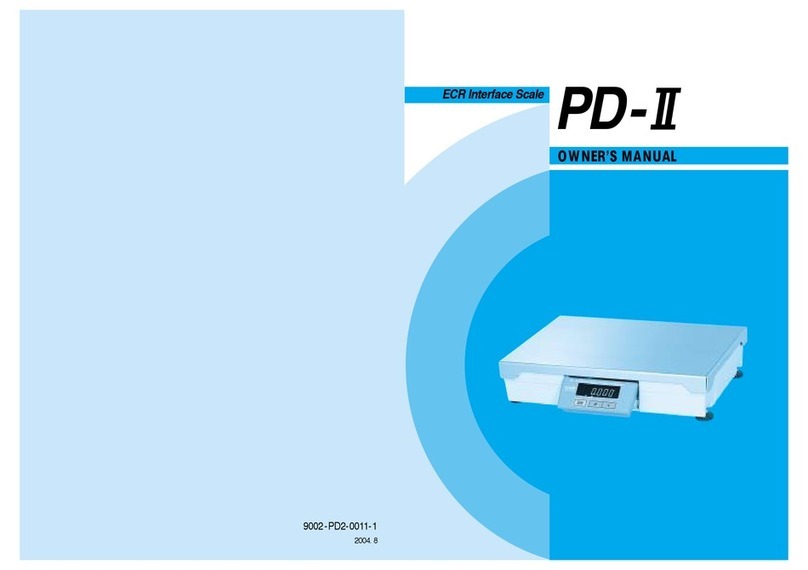
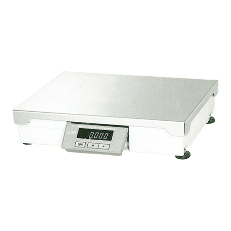
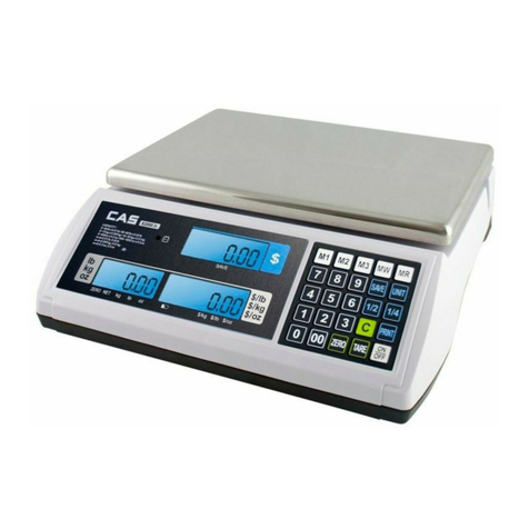
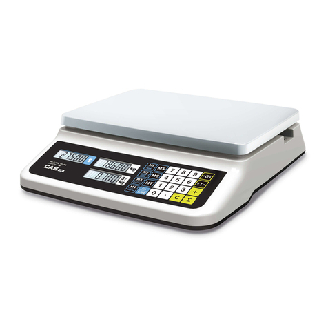
CAS PD-II User manual

1
PD-II MANUAL

2
< Table of Contents >
1. Introductions..................................................................................................................4
1.1. The Preface.....................................................................................................4
1.2. Precautions .....................................................................................................4
1.3. Specifications (CE) ..........................................................................................5
1.4. Sealing Method ...............................................................................................7
2. Calibration Mode ...........................................................................................................8
2.1. How to Go to Normal mode (C – 0) .................................................................9
2.2 How to Confirm Span Calibrated A/D Value(C – 1) .........................................9
2.2. Span Calibration(C – 3) .................................................................................10
2.3. Capacity Display and Option Setting(C – 4) ..................................................11
2.3.1. UNIT, TARE Setting(C–4–1) ....................................................................11
2.3.2. Capacity Setting(C–4–2) ..........................................................................11
2.3.3. Comma Setting (C–4–3)...........................................................................11
2.3.4. Save Setting(C–4–4) ................................................................................12
2.4. Averaging A/D Value(C - 5) ...........................................................................12
2.5. Real A/D Value(C – 6) ...................................................................................12
2.6. % Calibration (C – 7) .....................................................................................12
2.7. Gravity Constant (C – 9)................................................................................13
2.8. ECR INTERFACE..........................................................................................15
2.8.1 ECR Interface...........................................................................................15
2.8.2 ECR Type Selection .................................................................................15
Table 1..........................................................................................................................15
3. INTERFACE WITH EXTERNAL DEVICE....................................................................16
3.1. INTERFACE with RS-232C ...........................................................................16
3.1.1. TYPE-2 INTERFACE................................................................................16
3.1.2. TYPE-3 INTERFACE................................................................................17
3.1.3. TYPE-0 and TYPE-1 INTERFACE ...........................................................19
3.1.4. TYPE-4 INTERFACE................................................................................20
3.1.5. TYPE-5 INTERFACE................................................................................21
3.1.6. TYPE-6 INTERFACE................................................................................23
3.2. INTERFACE with 4-BIT PARALLEL ..............................................................24
3.2.1. TYPE-0 and1 INTERFACE.......................................................................24
3.2.2. COMMUNICATIONS BY USING UNIVERSAL 4-BIT PARALLEL ............27
4. The Schematics and Diagram .....................................................................................32
3
4.1. System Block Diagram ..................................................................................32
4.2. Circuit Diagram..............................................................................................33
4.2.1. Main..........................................................................................................33
4.2.2. Power .......................................................................................................34
4.2.3. Display......................................................................................................35
4.2.4. Communication (Serial and Parallel) .................................................36
4.3. Wiring Diagram..............................................................................................37
4.4. Parts Location ...............................................................................................38
4.4.1. Main and Power Part ................................................................................38
4.4.2. Display Part ..............................................................................................39
5. EXPLODED VIEW.......................................................................................................41
6. PARTS LIST................................................................................................................43

4
1. Introductions
1.1. The Preface
Thank you for purchasing of our CAS scale.
This scale has been designed with CAS reliability, under rigid quality control
and with outstanding performance.
Your departments can enjoy with this high quality reliable CAS product.
We believe that your needs will be satisfied and you will have proper reliability
with in variable weight.
This manual will help you with proper operations and care of the PD-II series.
Please keep it handy for the future references.
1.2. Precautions
To ensure that you get the most from your scale, please follow these instructions.
1. Do not disassemble the scale. When any damage or defect occurs, contact your CAS authorized
dealer immediately for proper repair.
2. Do not overload beyond the maximum weight limit.
3. Scale must be grounded to minimize electricity static. This will minimize defect or electric shock.
4. Do not pull the plug by its cord when unplugging. Damaged cord could cause electric shock or
fire.
5. To prevent from fire occurring. Do not place or use the scale near flammable or corrosive gas.
6. To reduce electric shock or incorrect reading. Do not spill water on the scale or place it in humid
condition.
7. Avoid placing the scale near heater or in direct sunlight.
8. Insert plug firmly to wall outlet to prevent electric shock.
Make sure to plug your scale into the proper power outlet. For maximum performance,
plug into a power outlet 30 minutes before the usage for warm up.
9. For consistent and accurate reading, maintain periodical check by your CAS authorized dealer.
10. Avoid sudden shock to the scale. Internal mechanism could be damaged.
11. Grab on the bottom of the scale when moving. Do not hold by the platter.
12. Place the scale on firm and temperature consistent environment.
13. If the scale is not properly level, please adjust the 4 legs at the bottom of the scale
(turn legs clockwise or counterclockwise) so as to center the bubble of the
leveling gauge inside the indicated circle.
14. Keep the scale away from other electromagnetic generating devices. This may interfere with
accurate reading.

5
1.3. Specifications (CE)
MODEL PDII – 6kg PDII – 15kg PDII – 30kg PDII-60kg
CAPACITY Single Interval
6 kg
Single Interval
15 kg
Single Interval
30 kg
Single Interval
60 kg
INTERNAL
RESOLUTION 1 / 90,000 1 / 90,000 1 / 90,000 1 / 90,000
EXTERNAL
RESOLUTION 1 / 3,000 1 / 3,000 1 / 3,000 1 / 3,000
TARE
SUBTRACTION -6kg – 15kg – 30kg -60kg
DISPLAY VFD 6 digit
DISPLAY LAMP ST, ZERO, NET, kg, lb
INTERFACE RS – 232C, 4-Bit Parallel Communication. (ECR Interface)
PRODUCT SIZE 380×280 ×79 [mm]
PLATTER SIZE 380 ×280 [mm]
OPERATING
TEMPERATURE - 10 °C ~ +40 °C
POWER
SOURCE AC 230 V / 50 Hz
OPTION Remote Display, Customer Display

6
Pound(lb) Version (UL)
MODEL PD2 – 15LB PD2 – 30LB PD2 – 60LB PD2-150LB
Capacity
Single Interval
15 lb / 0.005 lb
Dual Interval
6 lb / 0.002 lb
15 lb / 0.005 lb
Single Interval
30 lb/ 0.01 lb
Dual Interval
15lb / 0.005 lb
30 lb/ 0.01 lb
Single Interval
60 lb/ 0.02 lb
Dual Interval
30 lb/ 0.01 lb
60 lb/ 0.02 lb
Single Interval
150 lb / 0.05 lb
Dual Interval
60 lb / 0.02 lb
150 lb / 0.005 lb
INTERNAL
RESOLUTION 1 / 90,000 1 / 90,000 1 / 90,000 1 / 90,000
EXTERNAL
RESOLUTION 1 / 3,000 1 / 3,000 1 / 3,000 1 / 3,000
Display VFD 6 digit
DISPLAY LAMP STABLE, ZERO,TARE,kg, lb
INTERFACE RS – 232C, 4-Bit Parallel Communication.( ECR Interface )
PRODUCT SIZE 380×280 ×79 [mm]
PLATTER SIZE 380×280 [mm]
OPERATING
TEMPERATURE - 10 °C ~ +40 °C
OPTION Remote Display, Option Display
POWER
SOURCE AC 120 V / 60 Hz

7
1.4. Sealing Method

8
2. Calibration Mode
To go to calibration mode, turn on the power while pressing the calibration switch.
The display shows “CAL” three times, and then “C-0”.
Mode Selection : [TARE] or [UNIT] key
Enter : [ZERO] key
MODE DESCRIPTION
C – 0 Normal Mode
C – 1 Span calibrated A/D value
C – 3 Span Calibration
C – 4 Capacity Display and Option Setting
C – 5 Averaging A/D Value
C – 6 Real A/D Value
C – 7 % Calibration (10%~100%)
C – 9 Gravity Constant
Calibration Mode
MODE DESCRIPTION
C-4-1
Save Setting Calibration Unit, Tare setting
C-4-2
Capacity Setting Capacity setting
C-4-3
Comma Setting Commasetting
C-4-4
Capacity Setting Save setting
C – 4 Setting

9
2.1. How to Go to Normal Mode (C – 0)
To go to calibration mode, turn on the power while pressing the calibration switch. The
display shows “CAL” three times, and then “C-0”.
To go to Normal mode, press the [ZERO] key.
2.2 How to Confirm Span Calibrated A/D Value(C – 1)
(1) To go to calibration mode, turn on the power while pressing the calibration switch. The
display shows “CAL” three times, and then “C-0”.
(2) Press the [TARE] key until the display shows “C – 1” .
(3) Press the [ZERO] key, the display shows “0”.
(4) Place full capacity on the platter. The display shows “90,000”. If the number is not “90,000”,
press the lb/kg(*) or TARE key to have number up or down.
(5) Press the [ZERO] key, the display shows “C – 1”. You can change the mode by pressing
TARE or lb/kg(*) key.

10
2.2. Span Calibration(C – 3)
(1) To go to calibration mode, turn on the power while pressing the calibration switch. The
display shows “CAL” three times, and then “C-0”.
(2) Press the [TARE] key until the display shows “C – 3”.
(3) Press the [ZERO] key, the display shows “UnLOAd”.
(4) Remove items from the platter and press the [ZERO] key. The display shows “StAbLE”
and then “LOAd”. (If you want to finish this mode, press the TARE key.)
(5) Place full capacity on the platter and press the [ZERO] key. The display shows “C-3End”
and “C-3”.
(6) Remove full capacity from the platter. You can change the mode by pressing TARE or
lb/kg(*) key.

11
2.3. Capacity Display and Option Setting(C – 4)
For pariculars please inquire at CAS .
Key operation :
◆Press the ZERO key to enter setting value.
◆ Press the TARE key to change digit position.
◆ Press the lb/kg (* )key to have number Up.
2.3.1. UNIT, TARE Setting(C–4–1)
B7 B6 B5 B4 B3 B2 B1 B0
Display
Unit
Calibration
Unit NTEP
TARE Relase TARE
0:kg
1:lb
0: Others
0:TARE
1:TARE,
ZERO
0:Successive Tare
1:One time Tare
Don’t care
0:kg
1:lb
1: NTEP Don’t care Don’t care
2.3.2. Capacity Setting(C–4–2)
2.3.3.
B7 B6 B5 B4 B3 B2 B1 B0
CAPACITY INTERVAL
Kg lb
00011 6 15
00111 15 30
01001 30 60
01100 60 150
00 : Single
01 : Dual
2.3.4. Comma Setting (C–4–3)
B7 B6 B5 B4 B3 B2 B1 B0
Comma
Dislplay
1: Possible
0: Impossible

12
2.3.5. Save Setting(C–4–4)
B7 B6 B5 B4 B3 B2 B1 B0
UNIT
CHANGE
1: Possible
0: Impossible
If NTEP(C-4-1 3rd bit) is set, C-4-4 Setting don’t care.
2.4. Averaging A/D Value(C - 5)
(1) To go to calibration mode, turn on the power while pressing the calibration switch. The
display shows “CAL” three times, and then “C-0”.
(2) Press the [TARE] key until the display shows “C – 5”.
(3) Press the [ZERO] key, the display shows averaging A/D.
(4) Press the [ZERO] key to finish this mode.
(5) You can change the mode by pressing [TARE] or [lb/kg(*)] key.
2.5. Real A/D Value(C – 6)
(1) To go to calibration mode, turn on the power while pressing the calibration switch. The
display shows “CAL” three times, and then “C-0”.
(2) Press the [TARE] key until the display shows “C – 6”.
(3) Press the [ZERO] key, the display shows real A/D value.
(4) Press the [ZERO] key to finish this mode.
(5) You can change the mode by pressing [TARE] or [lb/kg(*)] key.
2.6. % Calibration (C – 7)
(1) To go to calibration mode, turn on the power while pressing the calibration switch. The
display shows “CAL” three times, and then “C-0”.

13
(2) Press the [TARE] key until the display shows “C – 7”.
(3) Press the [ZERO] key, the display shows “Per 10”.
(4) Press the [lb/kg] or [*] key to have number up or down The display shows 10, 20, 30, 40, 50,
60, 70, 80 and 90 every time pressing [kg/lb] or [*]key.
If you want to calibrate PDII-150lb with 30 lb, select 20.
(5) Press the [ZERO] key, the display shows “UnLOAd”.
(6) Remove items from the platter and press the [ZERO] key. The display shows “StAbLE”
and then “LOAd”.
(7) Place 20% weight of full capacity that you setup on step (3). And press the [ZERO] key, the
display shows “StAbLE” and then “C-7End”.
(6) Remove the weight from the platter. You can change the mode by pressing [TARE] or
[lb/kg(*)] key.
2.7. Gravity Constant (C – 9)
(1) To go to calibration mode, turn on the power while pressing the calibration switch. The
display shows “CAL” three times, and then “C-0”.
(2) Press the [TARE] key until the display shows “C – 9”.
(3) Press the [ZERO] key the display shows ”C91 “ and “ 9.7994”. Default value is 9.7994.
(4) You can change gravity constant for calibration place. Press the [lb/kg] or [*]key to have
number up or down. To move to next digit, press the [TARE] key.
(5) To save it, press the [ZERO] key. The display shows “C92” and “ 9.7994”.
(6) You can change gravity constant for using place. Press the [lb/kg] or [*] key to have number
up or down. To move to next digit, press the [TARE] key.
(7) Press the ZERO key, the display shows “C9-End” and “C – 9”.

14
(8) You can change the mode by pressing [TARE] or [lb/kg(*)] key.

15
2.8. ECR INTERFACE
2.8.1 ECR Interface
PD-II can interface with most ECRs by selecting TYPE 0 to TYPE 6.
2.8.2 ECR Type Selection
(1) Make sure that power is OFF. While pressing TARE key, turn on the power. “EcrSEt” is
shown on the display. And then current ECR type is shown on the display as “tYPE-2.
(2) If you select ECR type 5, press the TARE key until the display shows it. (Refer to Table 1.)
(3) To save current ECR type, press the ZERO key.
Table 1
※Serial Communication
9600 Baud rate, 7 Data bit, Even Parity, 1 Stop bit
Description
MENU 4-Bit Parallel RS-232 Serial
ECR-TYPE 0 TEC 4 Digit 4Bit Paralle (New kg)
ECR-TYPE 1 TEC 5 Digit 4Bit Paralle (Old kg)
Most P.O.S, ECRs and Some TEC P.O.S
System
ECR-TYPE 2 SHARP ER-Axxx, ER-A450T, New SANYO
ECRs using RS-232 and others
ECR-TYPE 3 Most P.O.S System
ECR-TYPE 4 CRS, NCR2170, SAMAUNG ER-5100,
ER5115 and Many other ECRs
ECR-TYPE 5
NCI General.
SAMSUNG ER-5100
Most P.O.S Software
ECR-TYPE 6
Universal 4 Bit Parallel
SAMSUNG ER-670

16
3. INTERFACE WITH EXTERNAL DEVICE
3.1. INTERFACE with RS-232C
7-BIT ASCII code
Even parity
1 stop bit
9600 baud rate
3.1.1. TYPE-2 INTERFACE
: Discontinual RS-232C Interface
SHARP ER-AXXX, ER-A450T, New SANYO ECRs using RS-232,TOLEDO 3213 etc.
1) PROTOCOL
ECR SCALE(PD-II)
Command ------------
<W>
------------ Response
<STX> 0XXXX <CR> : lb weighing mode
or <STX> XXXXX <CR> : kg weighing mode
Error message : <STX>?<status byte><CR>
== STATUS BYTE ==
PD-II
(9-PIN SUB CONNECTOR)
ECR(삼성), PC
D-SUB Connector
1
2
3
4
5
6
7
8
9
`
1
2
3
4
5
6
7
8
9
TxD
RxD

17
PARITY BIT ALWAYS==1 ZERO MINUS OVERLOAD MOTION
Bit 7 Bit 6 Bit 5 Bit 4 Bit3 Bit 2 Bit 1 Bit 0
cf) W : 57H (ASCII code)
STX : 02H (ASCII code)
CR : ODH (ASCII code)
Ex)
Weight : 12.34 lb
ECR SCALE
W<57H> ------
------ <02H><30H><31H><32H><33H><34H><0DH> : ASCII code
STX 0 1 2 3 4 CR
3.1.2. TYPE-3 INTERFACE
: Continual RS-232C Interface
SHARP ER-AXXX, New SANYO ECRs using RS-232,TOLEDO 3213 etc
1) PROTOCOL
ECR SCALE(PD-II)
Command ------------
<W>
------------ Response
<STX> 0XXXX <CR> : lb weighing mode
<STX> XXXXX <CR> : kg weighing mode
Error message : <STX>?<status byte><CR>
<CR> ------------Stop transmitting data
Ex)
Weight : 12.34 lb
ECR SCALE
W<57H> ------
------<02H><30H><31H><32H><33H><34H><0DH> : ASCII code

18
STX 0 1 2 3 4 CR
<02H><30H><30H><30H><30H><30H><0DH> : ASCII code
STX 0 0 0 0 0 CR
------<02H><3FH><44H><0DH>
STX ? MINUS CR

19
2) TRANSMISSION PROCEDURE
(1) PD-II sends data to External Device whenever weight is changed after receiving <W> signal
from the External Device.
(2) PD-II stops sending data when receives <CR> signal from the External Device.
External Device
<W> ------
----- DATA (If weight is changed)
------ DATA (If weight is changed)
<CR> ------Stop transmitting data
3.1.3. TYPE-0 and TYPE-1 INTERFACE
Most P.O.S Systems, ECRs and some TEC P.O.S Systems.
1) PROTOCOL
EXTERNAL DEVICE SCALE(PD-II)
<ENQ> ------------Initiate communication
<DC2> ------------Request of weight data
------------ <ACK> : Acknowledge the request of weight data
Inquiry
------------ <STX> : Start Transmission
------------ <ID> : Scale type identifier
------------ <W5> : Weight data
------------ <W4> : Weight data
------------ <W3> : Weight data
------------ <W2> : Weight data
------------ <W1> : Weight data
------------ <BCC> : Block Check Character
------------ <ETX> : End Transmission

20
i> Scale Type Identifier
ii> Block Check Character
: <BCC> has all data bytes except <STX> and <ETX> through exclusive OR(XOR).
* Parity Bit : Even
- Data Byte : <STX><ID><W5><W4><W3><W2><W1><BCC><ETX>
3.1.4. TYPE-4 INTERFACE
NCI ECR(NCR2170), SAMSUNG ER-5100,ER-5115, CRS .etc
1) PROTOCOL
<W> ------------
<CR> ------------
Inquiry
------------ <LF> XX.XXX LB <CR>
------------ <LF> S b1b2 <CR><ETX>
lb CASE
------------ <LF> XX.XXX KG <CR>
------------ <LF> S b1b2 <CR><ETX>
(A) XX.XXX = Weight value
(B) LB = The Characters L and B
(C) KG = The Characters K and G
(D) S = The Character S
(E) b1b2 = Two status Characters
41H = 15 kg 44H = 30 lb
43H = 6 kg 46H = 15 lb
NA = 3 kg NA = 6 lb
42H = 25 kg 45H = 50 lb
Other manuals for PD-II
5
This manual suits for next models
5
Table of contents
Other CAS Scale manuals

CAS
CAS ER PLUS SERIES User manual

CAS
CAS LP-II User manual

CAS
CAS GBF-1039 User manual

CAS
CAS LP 1.6 Series User manual

CAS
CAS NC-1 User manual

CAS
CAS ED Series User manual

CAS
CAS HE-30B User manual

CAS
CAS LP-II Installation and maintenance instructions

CAS
CAS CL-3000 Series User manual

CAS
CAS CT100 Series User manual