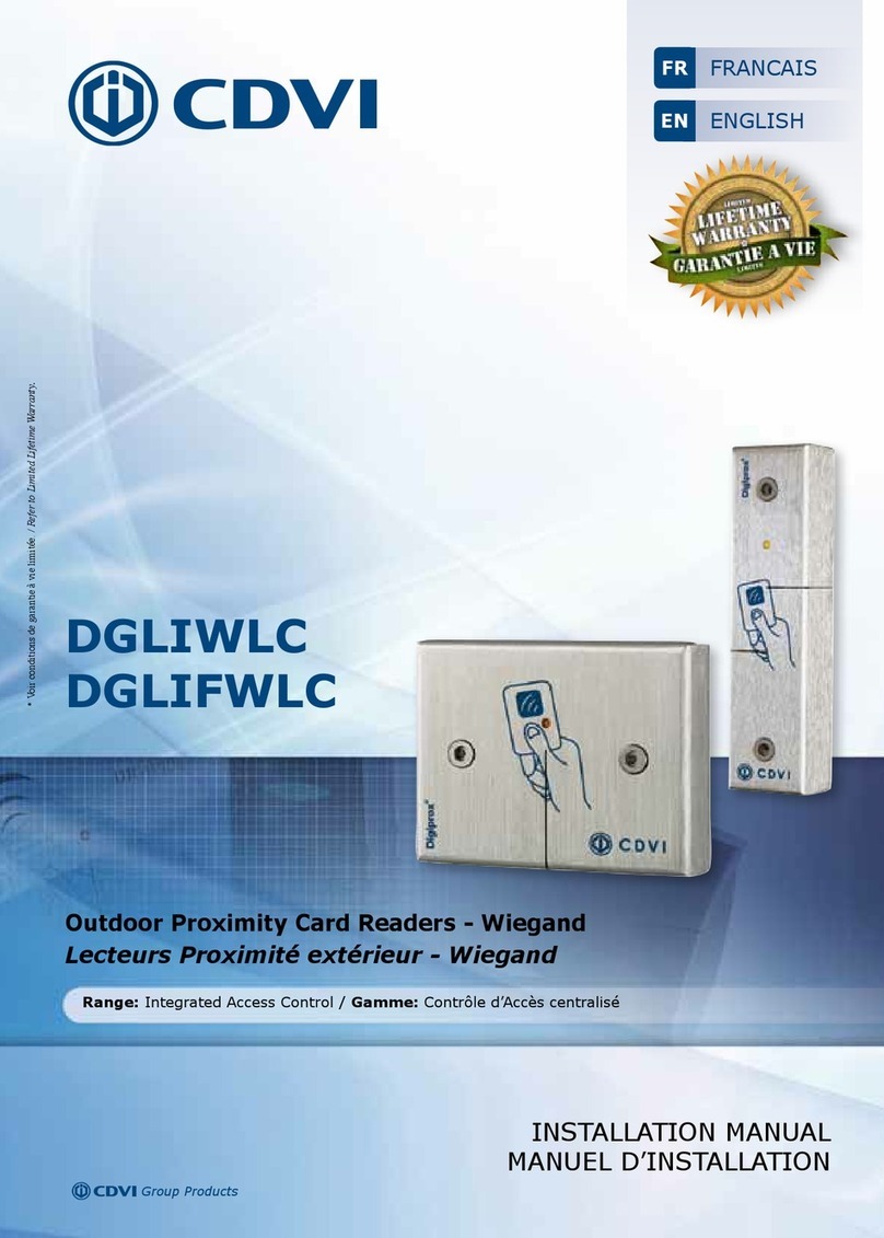
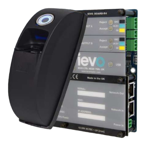
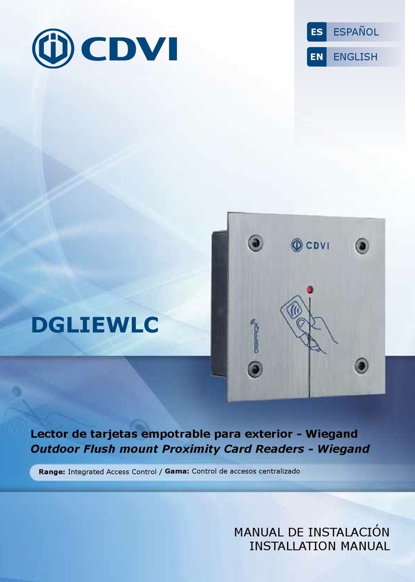
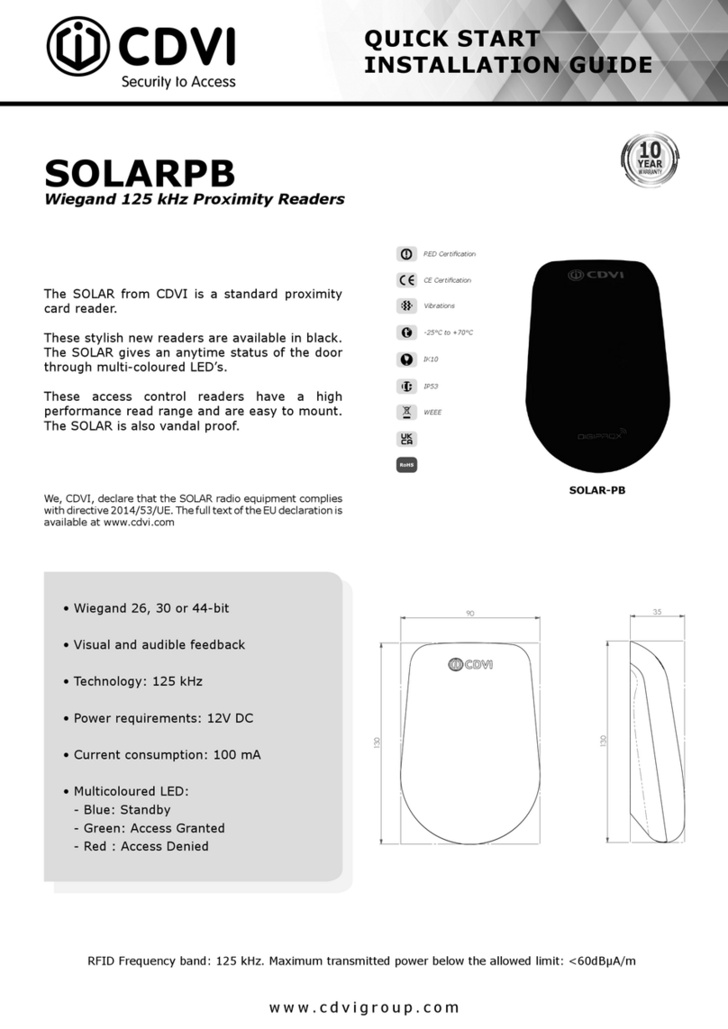
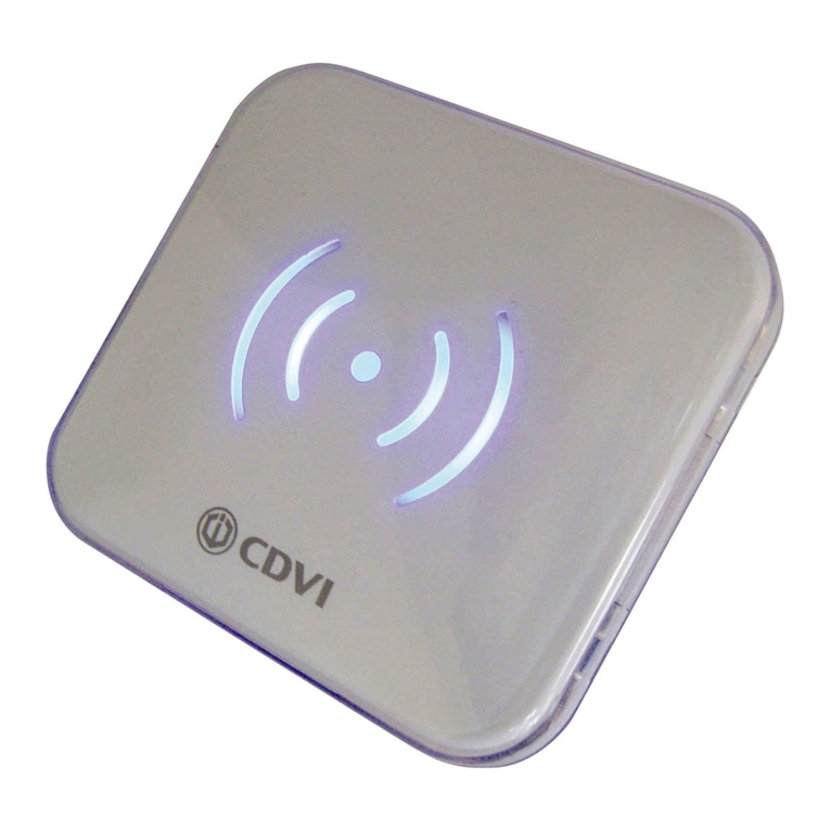
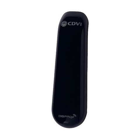
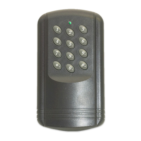
CDVI NANOPW User manual

The installer’s choice
cdvigroup.com
NANOPW
NANOPB
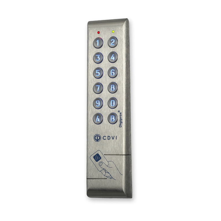
Wiegand 125 kHz Proximity Reader
Lector de proximidad Wiegand 125 kHz
ENGLISH
EN
ESPAÑOL
ES

ES
NANOPW - NANOPB
Lector de proximidad Wiegand 125 kHz
MANUAL DE INSTALACIÓN
Protocolo Wiegand 26/30/44 bits.
Conexión directa al control de accesos o a
través del controlador de puerta (INTBUSW).
Electrónica de control sellada en resina epoxi.
Señalización visual y sonora.
3 metros de cable.
Disponible en blanco y negro.
Dimensiones (A x A x P): 70 x 43 x 23 mm.
Tecnología: 125 kHz.
Protocolo: EM4100 (Marin).
Alimentación: 12 V DC.
Consumo: 100 mA.
1] PRESENTACIÓN DE PRODUCTO
3] ELEMENTOS INCLUIDOS
Junta de espuma Tornillo TF
3x30 Taco de plástico
S5
Cabezal para
destornillador
TORX®
Tornillo TORX®
3x8 Varistor
NANOPW(PB)
1 2 2 1 1 1
conforme parte 15
IP53
Gracias por la conanza que ha depositado en CDVI con la adquisición de este
producto.
2] NOTAS Y RECOMENDACIONES
Recomendaciones de
instalación
Para asegurar su instalación, no
se olvide de instalar los varis-
tores incluidos en paralelo a los
dispositivos de cierre.Para una
iluminación óptima, no deje
cable enrollado en el interior del
producto. Deje una distancia
mínima de 20 centímetros entre
dos lectores.
Cableado recomendado
Cable de 4 pares trenzado
0,60 mm (AWG 24).
Fuentes de alimentación reco-
mendadas
ARD12 y BS60, siempre que el
lector no sea alimentado por el
control de accesos o el INTBUSW.
Los lectores deben alimentarse
a 12 Vdc y las fuentes (diseña-
das para ser fuentes de bajo vol-
taje) deben estar conformes a
la norma
EN60950-1:2006/A11:
2009.
Entorno
Si se instalan en un entorno
cercano al mar, se recomienda
barnizar los bornes para prevenir
la oxidación.
Este producto se suministra
con un varistor.
Un varistor regula las sobreten-
siones causadas por la bobina
de la cerradura en su activación;
debe conectarse directamente a los
bornes de la cerradura (electrocer-
radura, ventosa) gestionada por el
equipo.
Si el control de accesos
gestiona varias cerraduras, cada
una debe tener su propio varistor.
En caso de usar una ventosa de
cizalla u otro tipo de cierre, se
recomienda usar una fuente de
alimentación exclusiva para el
cerradero.
2cdvigroup.com
3cdvigroup.com
1Mida y marque las posiciones del agujero del cableado
5 mm). Sírvase de la junta de espuma para ayudarse.
2Coloque la junta en la parte trasera del lector comen-
zando por la parte inferior-
salir aproximadamente 2 mm por encima de la tapa tra-
4] MONTAJE
Asegúrese de que todas las piezas necesarias están incluidas en la caja del producto. Utilice las herramientas
adecuadas para cada tipo de instalación (taladro, destornilladores, cinta métrica...) y siga las instrucciones de
montaje del lector NANOPW (PB).
1
3
2
3Coloque los tacos, pase el cableado y haga las conexiones (según el esquema indicado en este manual) y después
®® suminis-
Junta de espuma
ES
NANOPW - NANOPB
Lector de proximidad Wiegand 125 kHz
MANUAL DE INSTALACIÓN

ES
NANOPW - NANOPB
Lector de proximidad Wiegand 125 kHz
MANUAL DE INSTALACIÓN
Cuando conecte el lector
- Se ilumina el LED verde 1 segundo.
- Se ilumina el LED rojo 1 segundo.
- Se emite 1 pitido y el LED se vuelve azul.
Modo de funcionamiento
- El zumbador se activa con la entrada 0 Vdc.
- Los LED se activan con la entrada 0 Vdc.
1
ON
OFF
2
Cable
Rojo Alimentación 12 Vdc
Negro Alimentación 0 Vdc
Azul Clock
Verde Data 0
Blanco Data 1
Marrón Zumbador
Amarillo LED verde
Naranja LED rojo
LED verde LED rojo Estado
OFF OFF Inactivo
OFF ON Rojo
ON OFF Verde
ON ON Azul
5] ESQUEMA DE CABLEADO
Al presentar una tarjeta:
- Tarjeta leída: El LED se vuelve NARANJA 1 segundo y el zumbador se activa durante 150 milisegundos.
- Tarjeta no leída: No pasa nada.
- Acceso concedido: El LED se vuelve VERDE durante el tiempo de desbloqueo y se activa el zumbador.
- Acceso denegado: El LED se vuelve ROJO y el zumbador emite un pitido largo.
6] FORMATOS DE SALIDA WIEGAND EN 26, 30 Y 44 BITS
Cronogramas
Salidas en colector abierto con pull-up internos de 1K a +5 Vdc.
Lógica 0
\DATA1
\CLOCK
\DATA0
50 μs
50 μs
2ms
2ms
Lógica 1
Formatos de salida Wiegand
DIP1 DIP2 BITS
OFF OFF 26
ON OFF 30
OFF ON 44
4cdvigroup.com
5cdvigroup.com
FORMATO WIEGAND 26 BITS
1 - Primera paridad: 1 bit – paridad par durante los 12 primeros bits.
SN de la tarjeta: 6 mitades de byte representando los últimos 6 dígitos del SN (4bit = 1 dígito del SN)
Cada byte se transere desde el bit 7 hasta el 0.
2 - Segunda paridad: 1 bit – paridad impar durante los 12 últimos bits.
Bit 1 Bit 2 a bit 25 Bit 26
Paridad par de bit 2 a bit 13 Datos (24 bits)
Paridad impar de bit 14 a bit 25
Ejemplo:
1 0001 0110 0110 1010 0011 0111 0
Paridad 1 1 6 6 A 3 7 Paridad 2
Paridad 1 :
Paridad 2 :
ES
NANOPW - NANOPB
Lector de proximidad Wiegand 125 kHz
MANUAL DE INSTALACIÓN
FORMATO WIEGAND 30 BITS
1 - Primera paridad: 1 bit – paridad par durante los primeros 14 bits.
SN de la tarjeta: 7 mitades de byte representando el SN de la tarjeta.
Cada byte se transere desde el bit 7 al bit 0.
2 - Segunda paridad: 1 bit – paridad impar durante los últimos 14 bits.
Bit 1 Bit 2 a bit 29 Bit 30
Paridad par de bit 2 a bit 15 Datos (28 bits) Paridad impar de bit 16 a bit 29
Ejemplo:
1 0010 0001 0110 0110 1010 0011 0111 1
Paridad 1 2 1 6 6 A 3 7 Paridad 2
Paridad 1 : «0» si el número de «1» desde el bit 2 al bit 15 es par.
«1» si el número de «1» desde el bit 2 al bit 15 es impar.
Paridad 2 : «0» si el número de «1» desde el bit 16 al bit 29 es impar.
«1» si el número de «1» dedse el bit 16 al bit 29 es par.

ES
NANOPW - NANOPB
Lector de proximidad Wiegand 125 kHz
MANUAL DE INSTALACIÓN
FORMATO WIEGAND 44 BITS
Datos : SN de 10 dígitos en hexadecimal (MSByte en primer lugar).
Cada dígito en hexadecimal = 4 bits (MSByte en primer lugar).
LRC : 4 bit = O restringido entre los dígitos de los datos (MSByte en primer lugar).
Bit 1 a bit 40 Bit 41 a bit 44
SN de la tarjeta, MSByte primero LRC
Ejemplo:
0000 0001 0000 0000 0001 1001 0101 0000 1100 0011 0011
01001950C33
7] GESTIÓN DE LOS LED EN EL CONTROL DE ACCESOS CENTAUR
verte ACCeso ConCedido
rOjO ACCeso denegAdo
azul en stAnd-by
significado
de led
6cdvigroup.com
7cdvigroup.com
Wiegand 26/30/44 bits.
Direct connection.
PCB sealed in epoxy.
Audible and visual feedback.
3m pigtail wire connection.
Versions available: white or black.
L x W x D: 70 x 43 x 23mm.
Technology: 125 Khz.
Multi card protocol reader - Marin/HD.
Input voltage: 12V dc.
Consumption: 100mA.
1] PRODUCT PRESENTATION
3] MOUNTING KIT
2] REMINDERS AND RECOMMENDATIONS
Foam seal 3x30
TF screw S5
Plastic anchor TORX® bit 3x8
TORX®screw Varistor
NANOPW(PB)
1 2 2 1 1 1
Important
To protect the device from back-emf,
do not forget to install the varistor
across the lock terminals, in parallel.
For optimal illumination, do not
fold the cable inside the product.
Keep at least 20CM (8”) between
2 card readers.
Suggested power supplies
ARD12 & BS60 (in case the reader
is powered neither by the
controller nor by the reader
controller INTBUSW).
These products must be powered
in 12Vdc and the power supply
should be certied EN60950-
1:2006/A11:2009 standards
and should be designed to be
a low power supply source.
Recommended cables
4 twisted pairs 0.6mm (AWG 24).
Environment
When in a humid area or close to
the sea, we recommend applying
varnish to the terminals to avoid
oxidation.
This product is supplied
with a varistor.
The varistor must be connected
directly to the locking system
terminals (electric strikes,
electromagnet, or lock) operated
by the device. If the device
functions with several locking
systems, each one must be tted
with a varistor.
The varistor limits overload
produced by the strike coil,
known as self-effect or back-emf.
If you are using a “Shear Lock”,
electromagnet or other type of
electric lock, we recommend
the use of a dedicated power
supply for the lock.
part 15 compliance
IP53
Thank you for buying our products and for the condence you placed
in our company.
EN
NANOPW - NANOPB
Wiegand 125 Khz proximity reader
INSTALLATION MANUAL

EN
NANOPW - NANOPB
Wiegand 125 Khz proximity reader
INSTALLATION MANUAL
1Measure and mark the center lines to determine the
2Place the joint at the back of the reader. Take care
to begin from the bottom. (Sch. a). The joint must
be visible (about 2mm) on the top-back of the reader
(Sch. b).
4] MOUNTING
Make sure that there are no pieces missing from the mounting kit. Use the correct tools according to the installa-
tion (drill, screwdrivers, tape measure,...) and follow the mounting instructions of the reader.
1
3
2
Sch. a
Sch. b
Sch. c
3
®®bit (Sch. c). Make sure that the varistor is connected across the
8cdvigroup.com
9cdvigroup.com
When powered
- Green LED illuminates for 1 second
- Red LED illuminates for 1 second
- Buzzer sounds for 1 second
Operating mode
- Buzzer activated with 0V input
- LEDs activated with 0V input
Cable
Red Input voltage 12V dc
Black 0V
Blue Clock
Green Data 0
White Data 1
Brown Buzzer
Yellow Green LED
Orange Red LED
Green LED Red LED Status
OFF OFF OFF
OFF ON red
ON OFF green
ON ON blue
Wiegand output formats
DIP1 DIP2 BITS
OFF OFF 26
ON OFF 30
OFF ON 44
5] WIRING DIAGRAM
Card Swiped
- Badge recognized: the orange LED illuminates and the buzzer activates for 150 milliseconds.
1
ON
OFF
2
EN
NANOPW - NANOPB
Wiegand 125 Khz proximity reader
INSTALLATION MANUAL
6] OUTPUT FORMATS 26, 30 AND 44 BIT WIEGAND
Chronograms
0 logic
\DATA1
\CLOCK
\DATA0
50 μs 50 μs
2ms 2ms
1 logic

EN
NANOPW - NANOPB
Wiegand 125 Khz proximity reader
INSTALLATION MANUAL
26-BIT WIEGAND OUTPUT
1 - First parity: 1-bit – even parity for the rst 12-bit
Code of the badge: 6 half byte represent the last 6 digit of the code (4bit = 1 digit of a code)
Each byte is transferred from bit 7 to bit 0.
2 - Second parity: 1 bit – odd parity for the last 12-bit.
Bit 1 Bit 2 to bit 25 Bit 26
Even Parity on bit 2 to bit 13 Data (24 bit)
Odd Parity on bit 14 to bit 25
Exemple:
1 0001 0110 0110 1010 0011 0111 0
Parity 1 1 6 6 A 3 7 Parity 2
1 if the number of 1 in bit 2 to bit 13 is odd.
30-BIT WIEGAND OUTPUT
1 - First parity: 1 bit – even parity for the rst 14-bit
Code: A code is formed from 7 half byte.
Each byte is transferred from bit 7 to bit 0.
2 - Second parity: odd parity for the last 14-bit.
Bit 1 Bit 2 to bit 29 Bit 30
Even Parity from bit 2 to bit 15 Data (28-bit) Odd Parity from bit 16 to bit 29
Example:
1 0010 0001 0110 0110 1010 0011 0111 1
Parity 1 2 1 6 6 A 3 7 Parity 2
Parity 1: 0 if the number of 1 in bit 2 to bit 15 is even,
1 if the number of 1 in bit 2 to bit 15 is odd,
Parity 2: 0 if the number of 1 in bit 16 to bit 29 is odd,
1 if the number of 1 in bit 16 to bit 29 is even.
10 cdvigroup.com
11cdvigroup.com

7] LED MANAGEMENT ON CENTAUR SYSTEM
GREEN ACCESS ALLOWED
RED ACCESS DENIED
BLUE STAND-BY
LED
ACTUATION
EN
NANOPW - NANOPB
Wiegand 125 Khz proximity reader
INSTALLATION MANUAL
44-BIT WIEGAND FORMAT OUTPUT
Data: 10 digit code number hexadecimal MSByte rst.
Each hexadecimal digit = 4 bit, MSBit rst.
LRC: 4 bit = OR restricted in between the digit of the data, MSBit rst.
Bit 1 to bit 40 Bit 41 to bit 44
Data MSBit rst LRC
Example A:
0000 0001 0000 0000 0001 1001 0101 0000 1100 0011 0011
01001950C33

Referencia:
Extranet:
CDVI Group
FRANCE (Headquarter/Siège social)
Phone: +33 (0)1 48 91 01 02
Fax: +33 (0)1 48 91 21 21
CDVI
FRANCE + EXPORT
Phone: +33 (0)1 48 91 01 02
Fax: +33 (0)1 48 91 21 21
CDVI AMERICAS
[CANADA - USA]
Phone: +1 (450) 682 7945
Fax: +1 (450) 682 9590
CDVI
BENELUX
[BELGIUM - NETHERLAND - LUXEMBOURG]
Phone: +32 (0) 56 73 93 00
Fax: +32 (0) 56 73 93 05
CDVI
TAIWAN
Phone: +886 (0)42471 2188
Fax: +886 (0)42471 2131
CDVI
SUISSE
Phone: +41 (0)21 882 18 41
Fax: +41 (0)21 882 18 42
CDVI
CHINA
Phone: +86 (0)10 62414516
Fax: +86 (0)10 62414519
CDVI
IBÉRICA
[SPAIN - PORTUGAL]
Phone: +34 (0)935 390 966
Fax: +34 (0)935 390 970
CDVI
ITALIA
Phone: +39 0331 97 38 08
Fax: +39 0331 97 39 70
CDVI
MAROC
Phone: +212 (0)5 22 48 09 40
Fax: +212 (0)5 22 48 34 69
CDVI
SWEDEN
[SWEDEN - DENMARK - NORWAY - FINLAND]
Phone: +46 (0)31 760 19 30
Fax: +46 (0)31 748 09 30
CDVI
UK
[UNITED KINGDOM - IRELAND]
Phone: +44 (0)1628 531300
Fax: +44 (0)1628 531003
The installer’s choice
cdvigroup.com
could be perceptibly different and can be changed without prior notice.
Other manuals for NANOPW
2
This manual suits for next models
1
Table of contents
Languages:
Other CDVI IP Access Controllers manuals

CDVI
CDVI SOLARPW User manual

CDVI
CDVI MOONARW User manual

CDVI
CDVI SOLARPW User manual

CDVI
CDVI DGLIWLC User manual

CDVI
CDVI micro IEVO-M User manual

CDVI
CDVI KCPROXWLC User manual

CDVI
CDVI DGLIEWLC User manual

CDVI
CDVI PASS KCPASS User manual

CDVI
CDVI Digicode Mifare PCV123D User manual

CDVI
CDVI Ievo User manual

CDVI
CDVI GALEOR User manual

CDVI
CDVI KCPROXWLC User manual

CDVI
CDVI TERENA User manual

CDVI
CDVI Digicode Mifare PCV123D User manual

CDVI
CDVI DGLIWLC User manual

CDVI
CDVI PROMI500 User manual

CDVI
CDVI SOLARPB Instruction Manual

CDVI
CDVI STAR1M User manual

CDVI
CDVI BIOSYS 1 User manual

CDVI
CDVI KCPROXWLC User manual