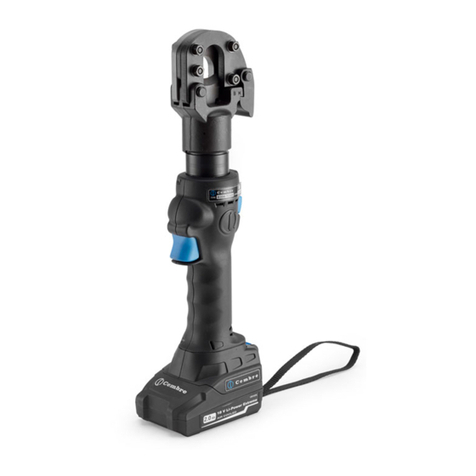
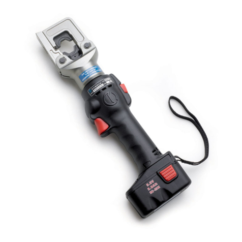
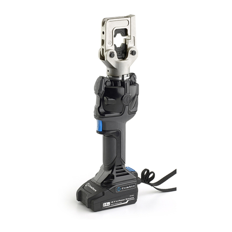
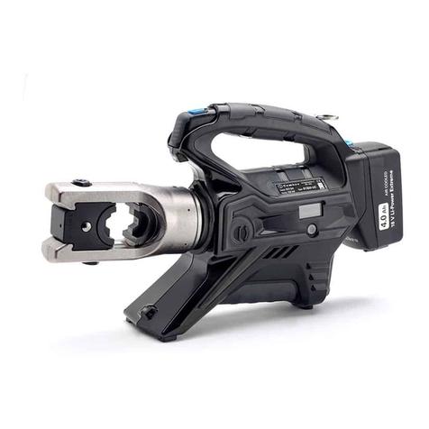
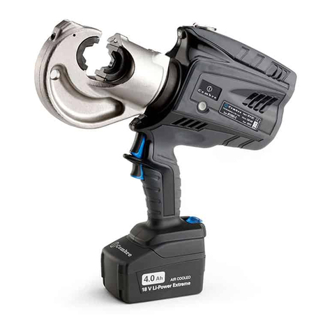
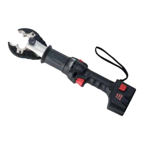
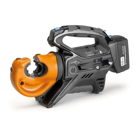
Cembre B135-UC User manual

ENGLISH
FRANÇAIS
DEUTSCH
ESPAÑOL
ITALIANO
BATTERY OPERATED HYDRAULIC CRIMPING TOOL
PRESSE HYDRAULIQUE SUR BATTERIE
HYDRAULISCHES AKKU-PRESSWERKZEUG
HERRAMIENTA HIDRAULICA DE COMPRESIÓN A BATERíA
UTENSILE OLEODINAMICO DA COMPRESSIONE A BATTERIA
13 M 054
OPERATION AND MAINTENANCE MANUAL
NOTICE D'UTILISATION ET ENTRETIEN
BEDIENUNGSANLEITUNG
MANUAL DE USO Y MANTENIMIENTO
MANUALE D'USO E MANUTENZIONE
B135-UC
B135-UCA
This manual is the property of
Cembre:
any reproduction is forbidden without written permission.
Ce manuel est la proprieté de
Cembre:
toute reproduction est interdite sauf autorisation écrite.
Der Firma Cembre bleibt das Eigentumsrecht der Bedienungsanleitung vorbehalten.
Ohne vorherige schriftliche Genehmigung darf die Bedienungsanleitung weder vollständig noch teilweise vervielfältigt werden.
Este manual es propiedad de
Cembre
.
Toda reproducción está prohibida sin autorización escrita.
Questo manuale è di proprietà della
Cembre:
ogni riproduzione é vietata se non autorizzata per scritto.
cod. 6261277
Cembre Ltd.
Dunton Park
Kingsbury Road, Curdworth - Sutton Coldfield
West Midlands B76 9EB (Great Britain)
Tel.: 01675 470440 - Fax: 01675 470220
E-mail: [email protected]
www.cembre.co.uk
Cembre S.p.A.
Via Serenissima, 9
25135 Brescia (Italia)
Telefono: 030 36921
Telefax: 030 3365766
E-mail: [email protected]
www.cembre.it
Cembre S.a.r.l.
22 Avenue Ferdinand de Lesseps
91420 Morangis (France)
Tél.: 01 60 49 11 90 - Fax: 01 60 49 29 10
B.P. 37 - 91421 Morangis Cédex
E-mail: [email protected]
www.cembre.fr
Cembre España S.L.
Calle Verano, 6 y 8 - P.I. Las Monjas
28850 Torrejón de Ardoz - Madrid (España)
Teléfono: 91 4852580
Telefax: 91 4852581
E-mail: [email protected]
www.cembre.es
Cembre AS
Fossnes Senter
N-3160 Stokke (Norway)
Phone: (47) 33361765
Telefax: (47) 33361766
E-mail: [email protected]
www.cembre.no
Cembre GmbH
Heidemannstraße 166
80939 München (Deutschland)
Telefon: 089/3580676
Telefax: 089/35806777
E-mail: [email protected]
www.cembre.de
Cembre Inc.
Raritan Center Business Park
181 Fieldcrest Avenue
Edison, New Jersey 08837 (USA)
Tel.: (732) 225-7415 - Fax: (732) 225-7414
E-mail: [email protected]
www.cembreinc.com
www.cembre.com
Certified Environmental
Management System Certified Occupational
Health & Safety
Management System
Certified Quality
M
anagement System

146
Deutsch
---------------------------------------------------------------------------------------------------------------------
INFORMATION FÜR DEN BENUTZER gemäß der “Richtlinien 2002/95/EG und 2002/96/
EG
in Bezug auf den reduzierten Gebrauch von gefährlichen Substanzen in elektrischen und
elektronischen Geräten, sowie auf die Abfallentsorgung”.
Das durchkreuzte Zeichen auf dem Mülleimer, welches auf dem Gerät oder seiner Verpackung ange-
bracht ist, zeigt an, dass das Produkt am Ende seiner Lebenszeit getrennt von den anderen Abfällen
entsorgt werden muss.
Die getrennte Abfallsammlung des vorliegenden zu entsorgenden Geräts wird vom Hersteller organi-
siert und verwaltet. Der Besitzer, der sich des Geräts entledigen will, muss sich daher mit dem Hersteller
in Verbindung setzen und das von ihm angenommene System für die getrennte Sammlung des zu
entsorgenden Geräts befolgen.
Eine angemessene getrennte Sammlung, damit das Gerät für das Recycling, die Behandlung und die
umweltfreundliche Entsorgung vorbereitet werden kann, trägt dazu bei, mögliche negative Auswir-
kungen auf die Umwelt und auf den Gesundheitszustand zu vermeiden und begünstigt die Wiederver-
wertung und das Recycling der Materialien des Geräts.
Bei widerrechtlicher Entsorgung des Produkts durch den Benutzer werden die vom Gesetz vorgesehen
Verwaltungssanktionen angewandt.
Español
----------------------------------------------------------------------------------------------------------------------
INFORME PARA LOS USUARIOS
en los términos de las
Directivas 2002/95/CE y 2002/96/
CE, relativas a la reducción en el empleo de sustancias peligrosas en los equipos eléctricos y
electrónicos, además de la eliminación de los desechos”.
El símbolo del contenedor de basura cruzado por un aspa que aparece en el equipo o sobre su emba-
laje indica que, al final de su ciclo de vida útil, el producto debe ser eliminado independientemente de
otros desechos.
La recogida selectiva del presente equipo, llegado al final de su ciclo de vida, es organizada y manejada
por el fabricante. El usuario que desee deshacerse del presente equipo deberá, por lo tanto, contactar
con el fabricante y seguir el sistema adoptado por el mismo para permitir la recogida por separado del
equipo que ha concluido su ciclo de vida.
La adecuada recogida selectiva, para el sucesivo envío del equipo dado de baja al reciclaje, al tratamiento
y al saneamiento ambiental compatible, contribuye a evitar posibles efectos negativos sobre el medio am-
biente sobre la salud favoreciendo el reempleo y el reciclaje de los materiales que componen el equipo.
La eliminación abusiva del equipo por parte del propietario implica la aplicación de las sanciones admi-
nistrativas prevista por la legislación vigente.
Italiano
------------------------------------------------------------------------------------------------------------------------
INFORMAZIONE AGLI UTENTI
ai sensi dell’art. 13 del Decreto Legislativo 25 Luglio 2005, n.
151 “
Attuazione delle Direttive 2002/95/CE e 2002/96/CE, relative alla riduzione dell’uso di sostanze
pericolose nelle apparecchiature elettriche ed elettroniche, nonché allo smaltimento dei rifiuti”.
Il simbolo del cassonetto barrato riportato sull’apparecchiatura o sulla sua confezione indica che il pro-
dotto, alla fine della sua vita utile, deve essere raccolto separatamente dagli altri rifiuti.
La raccolta differenziata della presente apparecchiatura giunta a fine vita è organizzata e gestita dal
produttore. L’utente che vorrà disfarsi della presente apparecchiatura dovrà quindi contattare il produt-
tore e seguire il sistema che questo ha adottato per consentire la raccolta separata dell’apparecchiatura
giunta a fine vita.
L’adeguata raccolta differenziata per l’avvio successivo dell’apparecchiatura dismessa al riciclaggio,
al trattamento ed allo smaltimento ambientalmente compatibile contribuisce ad evitare possibili effetti
negativi sull’ambiente e sulla salute e favorisce il reimpiego e/ il riciclo dei materiali di cui è composta
l’apparecchiatura.
Lo smaltimento abusivo del prodotto da parte del detentore comporta l’applicazione delle sanzioni am-
ministrative di cui all'articolo 50 e seguenti del D.Lg. n. 22/1997.
–
Before using the tool, carefully read the instructions in this manual.
– Avant d'utiliser cet outil, lire attentivement les instructions de cette notice.
– Vor Inbetriebnahme unbedingt die Bedienungsanleitung durchlesen.
– Antes de utilizar la herramienta, leer atentamente las instrucciones contenidas en este manual.
– Prima di utilizzare l'utensile, leggere attentamente le istruzioni contenute in questo manuale.
– When operating the tool, keep hands away from the danger zone.
– Au cours du sertissage, tenir les mains éloignées de la zone de travail.
– Während des Verpressens nicht mit den Händen in den Pressbereich gelangen.
– Durante su utilización, mantenga las manos fuera de la zona de peligro.
– Durante l'utilizzo, mantenere le mani fuori dalla zona di pericolo.
– Do not operate when dies are not in place.
– Insérer les matrices avant d'actionner l'outil.
– Nicht ohne Einsatzpaar betätigen.
– No poner en presión sin matrices.
–
Non mandare in pressione l'utensile senza le matrici inserite.
– Do not short circuit the batteries.
– Ne jamais court-circuiter les bornes d'une batterie.
– Schliessen Sie die Kontakte nicht kurz. Brandgefahr.
– No poner en cortocircuito las baterías.
– Mai mettere in corto circuito le batterie.
– Always recycle the batteries.
– Recycler toujours les batteries usagées.
– Verbrauchte Akkus stets dem Recycling zuführen.
– Reutilizar siempre las baterias.
– Riciclate sempre le batterie.
– Do not discard batteries into domestic refuse or waste disposal.
– Ne pas jeter de batteries dans une poubelle ou autre lieu non prévu à cet effet.
– Verbrauchte Akkus nicht in den Hausmüll werfen.
– No tirar las baterias al cubo de basura o lugar parecido.
– Non buttate le batterie fuori uso nei cestini della spazzatura o luoghi simili.
See page 45
Voir page 45
Siehe Seite 45
Vease página 45
Vedere pag. 45
WARNING LABELS - ETIQUETTES SIGNALETIQUES - WARNSCHILDER -
ETIQUETAS DE ATENCION - ETICHETTE D'AVVERTENZA
▲
!
TG0356

45 2
English
---------------------------------------------------------------------------------------------------------------------
USER INFORMATION
in accordance with “Directives 2002/95/EC and 2002/96/EC regarding
the reduction of hazardous substances in electrical and electronic equipment, including the
disposal of waste”.
The 'Not in the bin' symbol above when shown on equipment or packaging means that the equipment
must, at the end of its life, be disposed of separately from other waste.
The separate waste collection of such equipment is organised and managed by the manufacturer.
Users wishing to dispose of such equipment must contact the manufacturer and follow the prescribed
guidelines for its separate collection.
Appropriate waste separation, collection, environmentally compatible treatment and disposal is
intended to reduce harmful environmental effects and promote the reuse and recycling of materials
contained in the equipment.
Unlawful disposal of such equipment will be subject to the application of administrative sanctions
provided by current legislation.
Français
---------------------------------------------------------------------------------------------------------------------
INFORMATION POUR LES UTILISATEURS
Aux termes des “Directives 2002/95/CE et
2002/96/CE relatives à la réduction de l’utilisation de substances dangereuses dans les appa-
reils électriques et électroniques ainsi qu’à l’élimination des déchets”
Le symbole "poubelle barrée" apposé sur l’appareil ou sur son emballage indique que le produit, à la fin
de sa vie utile, doit être recueilli séparément des autres déchets.
La collecte sélective du présent appareil en fin de vie est organisée et gérée par le producteur. L’utilisa-
teur qui voudra se défaire du présent appareil devra par conséquent contacter le producteur et suivre le
système que celui-ci a adopté pour consentir la collecte séparée de l’appareil en fin de vie.
La collecte sélective adéquate pour l’envoi successif de l’appareil destiné au recyclage, au traitement
et à l’élimination compatible avec l’environnement contribue à éviter les effets négatifs possibles sur
l’environnement et sur la santé et favorise la réutilisation ou le recyclage des matériaux dont l’appareil
est composé.
L’élimination abusive du produit par le détenteur comporte l’application des sanctions administratives
prévues par les lois en vigueur.
–
Following information applies in member states of
the Europea Union:
– Les informations suivantes sont destinées aux pays
membres de l'Union Européenne:
–
Die folgenden Hinweise gelten für Mitglieder der
Europäischen Union:
– Las siguientes informaciones conciernen a los esta
dos miembros de la Unión Europea:
– Le seguenti informazioni riguardano gli stati membri
dell'Unione Europea:
R
R1
06
201
04
T
A
33
11
04 BATTERY CAPACITY INDICATOR / INDICATEUR DE CHARGE / LADEANZEIGE / INDICADOR DE
CARGA BATERIA / INDICATORE DI CARICA BATTERIA
06 OPERATING BUTTON / GACHETTE DE COMMANDE / STARTKNOPF / PULSADOR DE ACCIONA-
MIENTO / PULSANTE DI AZIONAMENTO
11 WRIST STRAP / DRAGONNE / HANDGURT / CORREA / CINGHIA POLSO
33 BATTERY / BATTERIE / AKKU / BATERIA / BATTERIA
41 RAM / PISTON / KOLBEN / PISTON / PISTONE
201 PRESSURE RELEASE LEVER / GACHETTE DE DECOMPRESSION / DRUCKABLASSHEBEL /
PALANCA DESBLOQUEO PRESION / LEVA SBLOCCO PRESSIONE
A"AU130-C" ADAPTOR / ADAPTATEUR / ADAPTER / ADAPTADOR / ADATTATORE
H"U" HEAD / TETE / KOPF / CABEZA / TESTA
RRING FOR SHOULDER STRAP / ANNEAU POUR BANDOULIERE / TRAGERIEMENRING /
R1 ANILLO PARA CORREA / ANELLO PER AGGANCIO TRACOLLA
TSHOULDER STRAP / BANDOULIERE / TRAGERIEMEN / CORREA DE TRANSPORTE / TRACOLLA
FIG. 1 OVERALL VIEW - VUE D'ENSEMBLE - GESAMTANSICHT
VISTA DEL CONJUNTO - VISTA D'ASSIEME
41
H

suitable for installing electrical compression connectors
for conductors up to 400 mm
2
(800 MCM) and
aluminium conductors up to 300 mm
2
(600 MCM)
130 (14.6)
700 (10,000)
376 x 94 x 302 (14.8 x 3.7 x 11.9)
14.4
AGIPARNICA 32 or SHELL TELLUS TX 32 or equivalent.
the tool has a twin speed operation and automatically
switches from a rapid advancing speed of the ram
to a slower, more powerful crimping speed.
the tool is equipped with a maximum pressure valve.
-15°C to +40°C (+5°F to +104°F)
ENGLISH
344
60
60
64 202
16
203
204
05
13
14
15
53
53
53
53
57
57
58
58
59
59
67
68 69
72
72
72
72
73
76
80
11
17
18
18
18
18
20
21
23
26
29
32
47
47
70
70
70
70
71
22
19
23
EXP0917 Rev.1 13-03-2013
TABLE 2 - TABLEAU 2 - TABELLE 2
- TABLA 2 - TAVOLA 2
BATTERY OPERATED HYDRAULIC CRIMPING TOOL
B135-UC ; B135-UCA
1. GENERAL CHARACTERISTICS
Application range:
Crimping force kN (sh ton):
Rated operating pressure bar (psi):
Dimensions
LxWxH
mm (inches):
Weight with battery kg (lbs):
Motor Volt DC:
Battery Volt / Ah:
Battery charger supply Volt / Hz:
Recommended oil:
Operating speed:
Safety:
Operating temperature:
Acoustic noise (Directive 2006/42/EC, annexe 1, point 1.7.4.2 letter u)
– The weighted continuous acoustic pressure level equivalent
A at the work place LpA is equal to .................................................................................75 dB (A)
– The maximum value of the weighted acoustic displacement
pressure C at the work place LpCPeak is.....................................................................< 130 dB (C)
– The acoustic power level emitted by the machine
LWA is equal to.............................................................................................................85,3 dB (A)
Risks due to vibration (Directive 2006/42/EC, annexe 1, point 2.2.1.1)
Testscarriedoutincompliancewiththe indications contained inUNIENV25349and UNI EN 28662
part 1st Standards, and under operating conditions much more severe than those normally found,
certify that the weighted root mean square in frequency of the acceleration the upper limbs
are exposed to for each biodynamic reference axis does not exceed 2.5 m/sec2.
TOOL TYPE: B135-UC
This hydraulic tool is powered by a 14.4V battery and is quiet in operation with minimal
vibration.
The residual battery capacity level is automatically displayed after every cycle.
B135-UCA
220 - 240 / 50 - 60 120 / 50 - 60
14.4 / 3.0 Ni-MH
14.4 / 3.0 Li-Ion
6,5 (14.3)6,2 (13.6)

The part reference "B135-UC ; B135-UCA" includes the following:
–Basic tool complete with battery and shoulder strap
– Spare battery
– Battery charger
– Plastic carrying case "VAL P9-C"
2. APPLICATION RANGE (Ref. to Figs. 2 and 4)
2.1) The tool is supplied with the AU130-C adaptor, which will accept semicircular slotted
dies (common to
Cembre
130 kN tooling) suitable for:
–Indentation on copper conductors.
–Circular compression on copper conductors.
–Hexagonal compression on copper, aldrey or aluminium conductors.
2.2) With the upper adaptor AU130-... and lower adaptor AC130-P, the tool can accept:
–Pre-rounding dies UP130-...
(used for converting aluminium sectoral conductor to a compact, round section).
–Containingdies(MV,MVC,MVM,MUAseries)andtherelevantindentorsPS130-.../E
(to crimp connectors on aluminium cables using the deep indent crimping system).
3. INSTRUCTIONS FOR USE (Ref. to Figs. 1 - 6)
3.1) Preparation
– The tool can be easily carried using either the handle or the shoulder strap (T) attached
to the rings (R and R1).
– With the tool in the rest position follow the procedure in § 3.6 (for copper cable) or § 3.7
(for aluminium cable):
3.2) Die advancement
Press the operating button (06) to acti-
vate the motor-pump and advance the
lower die. To halt the advancement,
release the operating button (06) and
the motor will cut out.
ENGLISH
43 4
200
201
205
206
02
03
04
08
12
30
33
34
35
38
40
42
43
44
45
51
52
54
56
55
61
63
65
74
75
77
78
79
89
90
39
48
48
49
49
36
37
41
46
62
82
84
83
85
86 87
87
88
45
44
45
43
NEVER PRESSURIZE THE TOOL
WITHOUTINSERTINGTHEDIES AS THIS
COULD CAUSE DAMAGE TO THE HEAD
AND THE RAM.
06
201
FIG. 3

ENGLISH
542
&RGH1
1FRGH
$UW1U
1FyGL
J
R
1FRGLFH
'(6&5,37,21'(6,*1$7,21%(6&+5(,%81*
'(6&5,3&,21'(6&5,=,21(
,WHP
3LqFH
7HLO
(OHPHQWR
&RPSRQHQWH
4W\4W
0HQJH
&GDG4W×
25,1*-2,17725,48(25,1*-817$'(*20$*8$51,=,21(250 .
25,1*-2,17725,48(25,1*-817$'(*20$*8$51,=,21(25 .
%86+'28,//(%8&+6(&$648,//2&$0,&,$
6($/-2,17',&+781*-817$'(*20$*8$51,=,21(
5,1*&211(&7,21&211(;,21$11($85,1*$16&+/866&21(;,Ï1$1,//2$77$&&2
$1(//2
&203/+($'7(7(&203/.203/.23)&$%(=$&203/7(67$&203/
8)25.)285&+(88*$%(/+2548,//$8)25&(//$8
*58%6&5(:9,66$167(7(,0%866&+5$8%(7251,//2*5$120;
+(;187(&5280877(578(5&$'$'20
35(65(/($6(/(9(5*$&+(77('('(&2035'58&.$%/$66+(%(/3$/$1&$'(
'(6%/35(6,21/(9$6%/2&&235(66,21(
&203/(7(+286,1*&$57(5&203/(7.203/(77(6*(+b86(&$5&$6$&203/(7$
&$57(5&203/(72
3,1*283,//(67,)73$6$'2563,1$&,/,1'5,&$';
&203/02725027(85&203/.203/0272502725&203/02725(&203/
:$6+(5521'(//(6&+(,%($5$1'(/$5$//$
6&5(:9,66&+5$8%(7251,//29,7(0[
*($5(1*5(1$*(*(75,(%((1*5$1$-(,1*56$7(//,7(
*($5(1*5(1$*(*(75,(%((1*5$1$-(,1*56$7(//,7(
*($5(1*5(1$*(*(75,(%((1*5$1$-(5827$$'(17,17(51$
*($5(1*5(1$*(*(75,(%((1*5$1$-(3,*121(0217$72
:$6+(5521'(//(6&+(,%($5$1'(/$521'(//$63(66
&,5&/,3$11($8(/$67)('(55,1*$1,//2(/$67$1(//2(/$67,&2
%($5,1*528/(0(17.8*(//$*(5&2-,1(7(*$%%,$
5,1*$11($85,1*$1,//2$1(//2,5;;
63$&(5(175(72,6(=:,6&+(167h&.',67$1&,$'25',67$1=,$/(
:$6+(5521'(//(6&+(,%($5$1'(/$526(77$'(17$7$0
5,1*$11($85,1*$1,//2$1(//2,5[[
(&&(175,&(;&(175,48((;(17(5(;&(175,&2(&&(175,&2
+286,1*&$57(5*(+b86(&$5&$6$&$57(5
%2'<&2536.g53(5&8(532&2532
&203/(7(5$03,6721&203/(79250217,(57(.2/%(13,67210217$'23,6721(
0217$72
&,5&/,3$11($8(/$67)('(55,1*$1,//2(/$67$1(//2(/$67'
%$&.835,1*$11($87()/67h7=5,1*$1,//23/$67,&2$1(//2%.
5$03,6721.2/%(13,67213,6721(
25,1*-2,17725,48(25,1*-817$'(*20$*8$51,=,21(25
&29(5&289(5&/(7$3$'(&.(/&23(5&+,202//$
635,1*5(66257)('(508(//(02//$(67(51$
635,1*5(66257)('(508(//(02//$,17(51$
5$0*8,'(68332573,6721.2/%(1)h+581*623257(3,6721)81*2
3,1$;('58&..123)3,6721&,//23,6721&,12
635,1*5(66257)('(508(//(02//$
3,1*283,//(67,)73$6$'2563,1$(/$67,&$'[
3,1$;('58&..123)3,6721&,//23,6721&,12
Make sure the dies are exactly positioned on the desired crimp point otherwise
reopen dies following instructions as per § 3.5 and reposition the connector.
3.3) Compression
– By keeping operating button (06) pressed, the motor continues to operate: the tool will
automaticallychangeovertothehighpressurestageandtheram(41)willgraduallymove
forward until the two dies touch.
– It is recommended to continue pumping until the maximum pressure valve is activated
and a "click" is heard.
– The motor will continue to operate after the maximum pressure relief valve has activate.
No further crimping force is applied, the oil is bypassed and returned to the reservoir.
3.4) Head rotation
Forease of operation,thetoolheadcan rotate through180°,allowingtheoperator to work
in the most comfortable position.
Warning: do not attempt to rotate the head when the hydraulic circuit is pressu-
rised.
3.5) Release of dies
By pressing the pressure release lever (201), the ram (41) will retract and open the dies.
3.6) CRIMPING OF CONNECTORS ON COPPER CABLES (Ref. to Figs. 2, 3)
3.6.1) Connector crimping
– Fit adaptor AU130-C (see § 3.6.2).
– Select the appropriate die set for the connector.
– Insert die set into upper and lower die holders (see § 3.6.3).
– Insert the conductor in the connector.
– Position the connector between the dies and ensure the correct location of the crimp.
– To crimp connector continue as § 3.2.
3.6.2) Adaptor assembly
InserttheAU130-C(09)adaptorintheguidesontheU-fork(33)untilsecurelylocated,with
the grooves on the adaptor corresponding to the locators (06) on the U-fork head (10).
Remove the adaptor by pushing the adaptor off the locators and sliding from the head.
3.6.3) Dies assembly
– Press release botton (08) and insert the upper die (88) into the AU130-C adaptor (09)
until secured by the die retaining pin (07).
Toremove theupperdie, presstherelease button(08)and slidethedie fromtheadaptor
(09).
– Press release botton (04) and insert the lower die (89) into the seat on the ram (14)
until secured by the die retaining pin (02).
To remove the lower die, press the release button (04) and slide the die from the ram.
To facilitate this operation an advancement of 3-4 mm (0.12 - 0.16 in.) of the ram (14) is
suggested.

ENGLISH
41 6
&RGH1
1FRGH
$UW1U
1FyGL
J
R
1FRGLFH
'(6&5,37,21'(6,*1$7,21%(6&+5(,%81*
'(6&5,3&,21'(6&5,=,21(
635,1*5(66257)('(508(//(02//$
+65$03,6721+9%8&+6(3,6721$93,6721($/7$9(/2&,7$
3803,1*5$03,6721'(3203$*(3803.2/%(13,6721%20%(23,6721(3203$17(
5(6(592,55(6(592,5g/7$1.'(326,726(5%$72,2
63$&(5(175(72,6(=:,6&+(167h&.',67$1&,$'25',67$1=,$/(
%$&.835,1*$11($87()/67h7=5,1*$1,//23/$67,&2$1(//2%. .
25,1*-2,17725,48(25,1*-817$'(*20$*8$51,=,21(25 .
25,1*-2,17725,48(25,1*-817$'(*20$*8$51,=,21(25 .
&$3:,7+0$*1(7%28&+21$9(&$,0$179(56&+/8660,70$*1(77$321&21,0$1
7$3326(5%$72,2&210$*1(7(
6($/-2,17',&+781*-817$*8$51,=,21(,1&$57$.
635,1*5(66257)('(508(//(02//$ .
3,1*283,//(67,)73$6$'2563,1$&,/,1'5,&$';
%86+'28,//(%8&+6(&$648,//2%8662/$
.(<&/$9(77(67h7=3/b7&+(1723(&+,$9(77$
6($/-2,17',&+781*-817$*8$51,=,21(3,(1$
6&5(:9,66&+5$8%(7251,//29,7(0;,12;
*58%6&5(:9,66$167(7(,0%866&+5$8%(7251,//2*5$12
635,1*5(66257)('(508(//(02//$ .
%$//%,//(.8*(/%2/$6)(5$ .
.(<&/$9(77(67h7=3/b7&+(1723(&+,$9(77$
25,1*-2,17725,48(25,1*-817$'(*20$*8$51,=,21(25 .
6&5(:9,66&+5$8%(7251,//29,7(0;
25,1*-2,17725,48(25,1*-817$'(*20$*8$51,=,21(25 .
'2:(//&/,48(7.8*(/+$/7(5623257(%2/$12772/,12
635,1*5(66257)('(508(//(02//$ .
635,1*5(66257)('(508(//(02//$$63,5$=,21( .
%$//%,//(.8*(/%2/$6)(5$ .
:$6+(5521'(//(6&+(,%($5$1'(/$526(77$0&8.
68&76&5(:9,6$63,5$16$8*6&+5$8%(7251,//268&9,7($63,5
6&5(:9,66&+5$8%(7251,//29,7(0;
6&5(:9,66&+5$8%(7251,//29,7(0;
&203/9$/9(9$/9(&203/.203/9(17,/9$/9&203/9$/92/$&203/
35(665(/($6(6&5(:9,6'('(&2035'58&.$%/$666&+5$8%(7251,//2'(6&$5*$
35(6,219,7(6&$5,&235(66,21(
6&5(:9,66&+5$8%(7251,//29,7(0[
3,1(0%28767,)7&217(5$3817$/(6&$5,&235(66,21(
635,1*5(66257)('(508(//(02//$ .
:$6+(5521'(//(6&+(,%($5$1'(/$526(77$'(17$7$0 .
7,(&2//,(5%,1'(5$%5$=$'(5$)$6&(77$
6($/-2,17',&+781*-817$'(*20$*8$51,=,21( .
6($/-2,17',&+781*-817$'(*20$*8$51,=,21( .
*58%6&5(:9,66$167(7(,0%866&+5$8%(7251,//2*5$12
3,1$;(67,)73(5123,6721&6%/2&&235(66,21(
,WHP
3LqFH
7HLO
(OHPHQWR
&RPSRQHQWH
4W\4W
0HQJH
&GDG4W×
TABLE 2 - TABLEAU 2 - TABELLE 2 - TABLA 2 - TAVOLA 2 (ITEM 20)
1 2 1 4 3 2
3.7) CRIMPINGOF CONNECTORSONALUMINIUM CABLES (Ref.toFigs.4, 5)
3.7.1) Pre-rounding conductor (for sectoral cables)
– From the table (Fig. 6, page 35) select the adaptors and pre-rounding dies for the ap-
propriate conductor size.
– Insert the upper adaptor AU130-... (98) and lower adaptor AC130-P (91) into the head
(see § 3.6.3).
– Insert the pre-rounding die into the AC130-P adaptor (see § 3.7.4).
– Position the conductor into the pre-rounding die (95) and locate the pre-rounding die in
theadaptor AU130-... (see §3.7.4).Ensurethat the pre-roundingdieiscorrectlylocated
in the adaptor with its upper slot in line with the internal adaptor pins.
– Operate the tool until the dies are fully closed.
Releasethehydraulicpressure (see§3.5) andremovethecompactedround conductor.
3.7.2) Connector crimping
– Remove the pre-rounding dies and the adaptor AC130-P from the head (see § 3.7.4).
– From the table (Fig. 6, page 35) select the containing die and indentor recommended
for the conductor size.
– Insert the indentor PS130.../E (93) into the ram (14) (see § 3.7.4).
– Insert conductor into the connector; locate the connector into the containing die; locate
the containing die in the adaptor (see § 3.7.4).
– Operate the tool, commence indent crimping from the barrel end for both splices and
terminals, following the sequence shown below.
– For every operation ensure the die is correctly located in the adaptor with its upper slots
in line with the internal adaptor pins.
– Each indenting operation is completed when indentor and die are fully closed;
it is recommended to continue pumping until the maximum pressure valve is activated
and a "click" is heard (see § 3.3).
3.7.3) Adaptor fitting and removal
–Insert the upper adaptor AU130-... (98) into the U-fork head (10) until secured by the
locators (34). To remove the adaptor from the U-fork head, push the adaptor from the
locators and slide out.
CRIMPING SEQUENCE
740
%
15
ENGLISH
See TABLE 2
Voir TABLEAU 2
Siehe TABELLE 2
Ver TABLA2
Vedere TAVOLA 2
xxxxxx
Serial number of tool
Numéro de série de l’outil
Seriennummer des Werkzeuges
Número de serie de la herramienta
Numero di matricola dell’utensile
– To insert the adaptor AC130-P (91), press the die release pin (04).
Insert the adaptor into the seat of the ram (14), until secured by the retaining pin (02).
To facilitate this operation, an advancement of 3÷4 mm (0.11 - 0.16 in.) of the ram (14)
is suggested.
To remove the adaptor, press the die release pin (04) and slide the adaptor from the
ram (14).
3.7.4) Dies, indentors, pre-rounding dies - fitting and removal (Ref. to Fig. 5)
– The containing die (96) and upper pre-rounding die (95): are located in the adaptor
AU130-... (98) by grooves in the upper face.
– The lower pre-rounding die (94): is inserted or removed from the adaptor AC130-P
(91),by pulling the release button (92).
– The indentor PS130.../E (93): is inserted into the seat on the ram (14).
3.8) Battery status
After releasing the operating button, the residual battery
capacity is automatically displayed for 5 seconds on the
indicator (15).
ThenumberofLEDsilluminatedindicatestheresidualcapacity:
10 LEDsilluminated: Fully charged
5 LEDsilluminated: 50 % capacity
1 LED illuminated: Minimum charge
When replacing the battery, press the two points marked with the word "PUSH" at the
same time, remove the flat battery from its housing and insert the new one.
4. WARNING
Before starting work on electrical equipment, please ensure that either there are no live
parts in the immediate working area or that precautions are taken for working near live
parts in accordance with EN50110-1.
DONOT USE THIS TOOL ON OR NEAR ENERGIZED CONDUCTORS WITHOUT PROPER
PERSONAL PROTECTIVE EQUIPMENT. FAILURE TO OBSERVE THIS WARNING COULD
RESULT IN SEVERE INJURY OR DEATH.
THE TOOL IS UNSUITABLE FOR CONTINUOUS USE AND SHOULD BE ALLOWED TO
COOLDOWNFOLLOWINGUNINTERRUPTED,SUCCESSIVECRIMPINGOPERATIONS;FOR
INSTANCE,HAVING EXHAUSTED AFULLY CHARGED BATTERY IN ONE SESSION,DELAY
BATTERY REPLACEMENT FOR AFEW MINUTES.
O
BSERVE RECOMMENDED REST PERIODS ALSO WHEN USING AN EXTERNAL POWER
SUPPLY.
PROTECT THE TOOL FROM RAIN AND MOISTURE. WATER WILL DAMAGE THE TOOL
AND BATTERY.ELECTRO-HYDRAULIC TOOLS SHOULD NOT BE OPERATED IN POURING
RAIN OR UNDER WATER.
05
06
13
17
18
20
31
31
33
32
EXP0916 Rev. 0 05-09-2006

39 8
TABLE 1 - TABLEAU 1 - TABELLE 1 - TABLA 1 - TAVOLA 1 4.1) Using the battery charger
Carefully follow the instructions in the battery charger manual.
4.2) General information on how to use batteries
In order to use the batteries correctly, please follow these rules:
– Use the battery until the automatic residual energy display still has 1-2 LEDs showing:
this means the battery is almost completely discharged and no loss in the life of the
battery has been caused.
– Be particularly careful when charging a new battery the first 2-3 times in order to be
certain of maximising the available energy level.
– Allow the battery to cool down to ambient temperature prior to recharging.
– Rest the battery charger for at least 15 minutes between charges.
5. MAINTENANCE
The tool is robust, completely sealed and requires very little daily maintenance.
Compliance with the following points should help to maintain the optimum performance
of the tool:
5.1) Thorough cleaning
Dust, sand and dirt are a danger for any hydraulic device.
Every day, after use, the tool must be wiped with a clean cloth taking care to remove any
residue, especially close to pivots and moveable parts.
5.2) Storage
When not in use, the tool should be stored
and transported in the plastic case, to prevent
damage. The case is suitable for storing the
tool and the accessories.
Plasticcase:VALP9-C,size543x412x130mm,
(21.4x16.2x5.1inches)weighs2,2kg(4.8lbs)is
suitableforstoringthetool,theaccessoriesand
up to 8 sets of semi-circular slotted dies .
IsavailableVAL130steelcase:size360x280x48
mm(14.17x11x1.89 in.), weight 3 kg (6.62 lbs),
for storage of the accessories for crimping
aluminium connectors.
6. RETURN TO
Cembre
FOR OVERHAUL
In the case of a breakdown contact our Area Agent who will advise you on the problem
andgiveyouthe necessary instructions on how to dispatchthetooltoournearest service
Centre; if possible, attach a copy of the Test Certificate supplied by
Cembre
together
with the tool or, if no other references are available, indicate the approximate purchase
date and the tool serial number.
ENGLISH
05
10
04
05
08
09
10
11
15
19
01
03
03
04
04
43
44

Domaine d'application:
Force de sertissage kN (sh ton):
Pression nominale bar (psi):
Dimensions
LxLxH
mm (inches):
Poids avec batterie kg (lbs):
Moteur Volt DC:
Batterie Volt / Ah:
Chargeur de batterie Volt / Hz:
Huile recommandée:
Avance rapide:
Sécurité:
Température de fonctionnement:
938
The guarantee is void if parts used are not Cembre original spares.
La garantie perd tout effet en cas d’emploi de piéces détachées différentes des pièces d’origine Cembre.
Die Garantie verfällt, wenn nicht Originalteile aus dem Hause Cembre in das Gerät eingebaut werden.
La garantía pierde su valor si se utilizan piezas de repuesto distintas de las originales Cembre.
La garanzia decade qualora vengano utilizzate parti di ricambio non originali Cembre.
&RGH1
1FRGH
$UW1U
1FyGL
J
R
1FRGLF
H
'(6&5,37,21'(6,*1$7,21%(6&+5(,%81*
'(6&5,3&,21'(6&5,=,21(
/$%(/(7,48(77(6&+,/'(7,48(7$(7,&+(77$7*
5,1*&211(&7,21&211(;,21$11($85,1*$16&+/866&21(;,
Ï
1
$
1,//2$77$&&2$1(//2
%87721*$&+(77(67$57.123)38/6$'2538/6$17(%/8
6&5(:9,66&+5$8%(7251,//29,7(;
6&5(:9,66&+5$8%(7251,//29,7(;
6&5(:9,66&+5$8%(7251,//29,7(;
:5,67675$3'5$*211(+$1'*857&255($&,1*+,$32/62
3,1*283,//(67,)73$6$'2563,1$&,/,1'5,&$';
6&5(:9,66&+5$8%(7251,//29,7(;
635,1*5(66257)('(508(//(02//$
/$%(/(7,48(77(6&+,/'(7,48(7$(7,&+(77$7*
/$%(/(7,48(77(6&+,/'(7,48(7$(7,&+(77$7*
0(&+$1,&$/*5283*5283(0(&$1,48(0(&+$1,6&+(*5833(*5832
0(&$1,&$*583320(&&$1,&$
5,1*$11($85,1*$1,//2$1(//2
(/(&75,&&,5&8,76+(//6&,5&8,7(/(&75,48(&248,//(667520.5(,6
0,7*(+b86(&,5&8,72(/(&75,&2&$5&$6$6
&,5&8,72(/(775,&2*86&,
(/(&75,&&,5&8,76+(//6&,5&8,7(/(&75,48(&248,//(667520.5(,6
0,7*(+b86(&,5&8,72(/(&75,&2&$5&$6$6&,5&8,72
(/(775,&2*86&,
6&5(:9,66&+5$8%(7251,//29,7(;
3,1*283,//(67,)73$6$'2563,1$&,/,1'5,&$';
&203/(/(&75&,5&8,7&,5&8,7(/(&75&203/.203/67520.5(,6
&,5&8,72(/(&75&203/&,5&8,72(/(75,&2&203/
%$77(5<%$77(5,($..8%$7(5,$%$77(5,$9$K
/$%(/(7,48(77(6&+,/'(7,48(7$(7,&+(77$7*
/$%(/(7,48(77(6&+,/'(7,48(7$(7,&+(77$7*
4W
\
4Wq
0HQJH
&GDG
4Wj
,WHP
3LqFH
7HLO
(OHPHQWR
&RPSRQHQWH
TABLE 1 - TABLEAU 1 - TABELLE 1 - TABLA 1 - TAVOLA 1
FRANÇAIS
PRESSE HYDRAULIQUE SUR BATTERIE TYPE
B135-UC ; B135-UCA
1. CARACTERISTIQUES GENERALES
OUTIL TYPE: B135-UC
Pression sonore aérienne (Directive 2006/42/CE, annexe 1, point 1.7.4.2, lettre u)
– Le niveau de pression sonore continue équivalente
pondérée A sur le poste de travail LpA est....................................................................75 dB (A)
– Le niveau de pression sonore instantanée pondérée
C sur le poste de travail LpCPeak est ..........................................................................< 130 dB (C)
– Le niveau de puissance acoustique dégagée par la
machine LWA est.........................................................................................................85,3 dB (A)
Risques dérivés des vibrations (Directive 2006/42/CE, annexe 1, point 2.2.1.1)
Des relevés réalisés suivant les indications des Normes UNI ENV 25349 et UNI EN 28662 partie
1a, dans des conditions de service largement représentatives des conditions d'emploi normales
témoignent que la valeur quadratique moyenne pondérée en fréquence de l'accélération à laquelle
sont exposés les membres supérieurs pour chaque axe biodynamique de référence ne dépasse
pas les 2,5 m/sec2.
conçue pour le sertissage des connecteurs pour câbles
jusqu'à 400 mm2(800 MCM) et pour câbles
en aluminium jusqu'à 300 mm2(600 MCM).
130 (14.6)
700 (10,000)
376 x 94 x 302 (14.8 x 3.7 x 11.9)
14.4
AGIPARNICA 32 ou SHELL TELLUS TX 32 ou équivalents
l’outil passe automatiquement
de la vitesse rapide d’approche des matrices
à la vitesse lente de sertissage.
l’outil est équipé d'une valve de surpression.
-15°C à +40°C (+5°F à +104°F)
La presse hydraulique fonctionne sous une alimentation de 14,4 V apportée par une
batterie. Il s’agit d’un outil silencieux et dépourvu de vibrations.
L’affichage automatique du niveau de charge de la batterie visible à la fin de chaque
opération permet de connaître l’autonomie disponible.
B135-UCA
220 - 240 / 50 - 60 120 / 50 - 60
14.4 / 3.0 Ni-MH14.4 / 3.0 Li-Ion
6,5 (14.3)
6,2 (13.6)

FRANÇAIS
37 10
English
---------------------------------------------------------------------------------------------------------------------
Spare parts kit code no. 6000057 including items marked "K" in table is available as an accessory.
When ordering spare parts always specify the following:
- code number of item
- name of item
- type of tool
- serial number of tool
Français
---------------------------------------------------------------------------------------------------------------------
Un kit de pièces détachées est disponible sous le code article 6000057. Il comprend les pièces
repérées par la lettre “K”.
Lors de la commande de pièces détachées, veuillez indiquer toujours les éléments suivants:
- numéro de code article de la pièce
- désignation de la pièce
- type de l'outil
- numéro de série de l'outil
Deutsch
---------------------------------------------------------------------------------------------------------------------
Auf Anfrage kann das Ersatzteilkit Bestell-Nr. 6000057 mit allen Ersatzteilen, die mit "K" markiert
sind, geliefert werden.
Geben Sie bitte bei der Bestellung aller Ersatzteile folgende Informationen an:
- Artikelnummer des Ersatzteils
- Beschreibung des Ersatzteils
- Werkzeug Typ
- Seriennr. des Werkzeuges
Español
---------------------------------------------------------------------------------------------------------------------
Bajodemanda estádisponible elPaquete de repuesto cod. 6000057 que comprendelos elementos
marcados con la "K".
Al pedir piezas de repuesto, indicar siempre los elementos siguientes:
- número de código del elemento
- descripción del elemento
- tipo de herramienta
- número de serie de la herramienta
Italiano
-----------------------------------------------------------------------------------------------------------------------
Arichiesta, é disponibile la Confezione ricambio cod. 6000057 comprendente i particolari contras-
segnati dalla lettera "K".
Per ordinare parti di ricambio, specificare sempre i seguenti punti:
- numero di codice del componente
- denominazione del componente
- tipo di utensile
- numero di matricola dell'utensile
La référence “B135-UC ; B135-UCA” désigne l'ensemble suivante:
–Outil de base avec batterie, dragonne et bandoulière
–Batterie de rechange
–Chargeur de batterie
–Coffret de rangement en plastique “VAL P9-C”
2. DOMAINE D’APPLICATION (Voir Fig. 2 et 4)
2.1) L’équipement standard de l’outil comprend l’adaptateur AU130-C avec lequel il peut
recevoir divers types de matrices (communes également aux autres outils
Cembre
de
130 kN) destinées au:
–Poinçonnage sur câble cuivre.
–Sertissage semi-circulaire sur câble cuivre.
–Sertissage hexagonal sur câble cuivre, almélec ou aluminium.
2.2) Avec les adaptateurs types AU130-... et AC130 P, l’outil peut recevoir les:
– Matrices de mise au rond UP 130-..., ramenant les câbles sectoraux à la forme cir-
culaire.
–Matrices coquille séries MV,MVM,et les poinçons PS130-.../E réalisant un poinçon-
nage profond, matrice fermée, sur câble aluminium.
3. INSTRUCTIONS D'UTILISATION (Voir Fig. 1 - 6)
3.1) Mise en service
– L’outil peut être transporté facilement grâce à sa poignée et à la bandoulière (T) accro-
chée par les anneaux (R).
– Avec l’outil en position repos, suivant le processus decrit au § 3.6 (dans les cas d'un
câble en cuivre) ou § 3.7 (dans les cas d'un câble en aluminium).
3.2) Avance des matrices
Appuyer sur la gâchette de commande
(06) pour mettre en marche le groupe
moteur pompe; les matrices commen-
cent alors à se rapprocher du connec-
teur. La gâchette de commande (06)
relâchée, le moteur et l'avance des
matrices cessent immédiatement.
NEJAMAIS METTRE L’OUTIL
SOUSPRESSIONSANSAVOIR INSERE
LES MATRICES, CELA POURRAIT
ENDOMMAGER LES SIEGES DE LA
TETE ET DU PISTON.
06
201

11 36
SPARE PARTS LIST
PIECES DETACHEES
ERSATZTEILLISTE
LISTA DE PIEZAS DE REPUESTO
LISTA DEI RICAMBI
B135-UC
B135-UCA
S'assurerqueles matrices sont bien positionées sur la zone à sertir, sinon desserer
les matrices en suivant les instructions du § 3.5 et repositioner le connecteur.
3.3) Sertissage
– En maintenant pressée la gâchette de commande (06), on maintient la rotation du
moteur; le piston avance progressivement jusqu'à ce que les matrices arrivent en butée
l'une contre l'autre.
– Nous recommandons en tout cas d'actionner le moteur jusqu'au déclenchement de la
valve de surpression que l'on entendra distinctement.
– Après ce déclenchement, même si l'on maintient le moteur actionné, on n'obtiendra
aucune poussée sur les matrices car l'huile sera déviée directement au réservoir.
3.4) Rotation de la tête
La tête de l'outil pivote de 180° par rapport au corps, permettant à l'utilisateur de travailler
dans la meilleure position.
Attention: ne pas forcer la rotation de la tête, lorsque le circuit hydraulique est
sous pression.
3.5) Réouverture des matrices
En appuyant à fond sur la gâchette de déblocage pression (201) qui se trouve sur le corps
de l'outil sous la gâchette de commande (06), on provoque le retour du piston et par con-
séquent l'ouverture des matrices.
3.6) SERTISSAGE SUR CONNECTEURS POUR CABLES EN CUIVRE
(Voir Fig. 2 et 3)
3.6.1) Exécution des sertissages
– Monter l’adaptateur AU130-C (09) (voir § 3.6.2).
– Prendre les matrices à utiliser selon les indications du catalogue.
– Insérer les matrices à leur place (voir §3.6.3).
– Insérer le conducteur dans le connecteur à utiliser.
– Positionner ce dernier entre les deux matrices en faisant coincider la zone à sertir et
l’empreinte des matrices.
– Après celà,opérer selon les indications du § 3.2.
3.6.2) Montage de l'adaptateur
– Insérerl’adaptateurAU130-C(09)danslesguidesdelafourche(10)etlepousserjusqu’à
son blocage, par les billes (06).
– Pour le démonter pousser avec force jusqu’au dégagement des billes (06).
3.6.3) Montage des matrices
– Insérer la matrice supérieure (88) dans l’adaptateur AU130-C (09) en appuyant sur le
poussoir (08) et la pousser jusqu’à ce que l’ergot (07) la verrouille.
Pour la dégager appuyer sur le poussoir (08) et la faire glisser.
– Insérer la matrice inférieure (89) dans les guides du piston (14) en appuyant sur le
poussoir (04) et la pousser jusqu’à ce que l’ergot (02) la vérouille.
Pour la dégager appuyer sur le poussoir (04) et la faire glisser.
Cette opération est facilitée par l’avancement de 3-4 mm du piston (14).
FRANÇAIS

35 12
UP 130-25
UP 130-35
UP 130-50
UP 130-70
UP 130-95
UP 130-120
UP 130-150
UP 130-185
UP 130-240
UP130-300
10 - 16
25
35
50
70
95
120
150
185
240
300
AC 130-P
AU 130-150
AU 130-240
PS 130-35/E
MV 35 MVM 35 MUA 35
CONNECTORS - CONNECTEURS - VERBINDER - CONECTORES - CONNETTORI
CAA..-M MTMA... MTA... AA...M
MTA..-C
Conductor section
Section conducteur
Leiter Querschnitt
Sección cable
Sezione cavo
( mm2 )
Upper adaptor
Adaptateur superieur
Werkzeughalter
Adaptador superior
Adattatore superiore
Lower adaptor
Adaptateur inferieur
Halter
Adaptador inferior
Adattatore inferiore
Pre-rounding die
Matr. de mise au rond
Runddrückeinsätze
Preredondeador
Prearrotondatore
Indentor
Poinçon
Stempel
Punzón
Punzone
Long - Longue - Lang - Larga -Lunga
Universal - Universelles
Universal -Universale
Universale
Containing die - Matrice coquille - Presseinsatzschale -
Matrice de sujección - Matrice di contenimento
Short - Courte -
Kurz - Corta - Corta
PS 130-95/E
MV 95 MVM 95 MVC 95 MUA 95
PS 130-150/E
MV 150 MVM 150 MVC 150 MUA 150
MUA 300-34
Aluminium
Aluminio
Alluminio
MV 240 MVM 240 MVC 240 MUA 240
*
PS 130-240/E
Outside diameter of connector = 34mm
Diametre exterieur connecteur = 34mm
Verbinder Aussendurchmesser = 34mm
Diametro externo conector = 34mm
Diametro esterno connettore = 34mm
FIG. 6 GUIDE TO THE SELECTION OF ACCESSORIES - GUIDE POUR LA SELECTION DES ACCESSOIRES
- ZUBEHÖR FÜR DIE TIEFNUTKERBUNG - GUIA PARA LA ELECCIÓN DE ACCESORIOS
GUIDA PER LA SCELTA DEGLI ACCESSORI
*
3.7) SERTISSAGE SUR CONNECTEURS POUR CABLES EN ALUMINIUM
(Voir Fig. 4 et 5)
3.7.1) Mise au rond du câble
– Prendrelesaccessoiresetlesmatricesdemiseaurondselonlesindicationsdutableau
Fig. 6, page 35.
– Monter sur la tête les adaptateurs AU130-... (98) et AC130-P (91) (voir § 3.7.3).
– Insérer la partie mobile (94) de la matrice de mise au rond dans l'adaptateur AC 130-P
(voir § 3.6.4).
– Insérerle câble à l’intérieurdelapartiefixe(95) de la matricedemiseaurond et position
ner ensuite cette dernière dans l'adaptateur AU130-... (voir § 3.7.4) en faisant coïncider
la rainure supérieure présente sur la matrice avec les goupilles localisées à l'intérieur
de l'adaptateur.
– Actionner l'outil jusqu’à porter au contact les matrices de mise au rond, relacher ensuite
la pression et libérer le câble (voir § 3.5).
3.7.2) Exécution des sertissages
– Enlever de la tête les matrices de mise au rond et l'adaptateur AC130-P (voir § 3.7.4).
– Prendre l'ensemble matrice-poinçon à utiliser selon les indications du tableau Fig. 6,
page 35.
– Insérer le poinçon PS130.../E (93) dans le logement du piston (09) (voir § 3.7.4).
– Insérer le conducteur dans le connecteur.
– Insérerle connecteur dansla matricecoquille etpositionner ensuitecette dernièredans
la tête (voir § 3.7.4).
– En actionnant l'outil commencer à sertir le connecteur en partant, pour les manchons,
de l'extrémité vers l’intérieur et pour les cosses de l'extrémité arrière vers la plage (voir
figure). Positionner chaque fois la matrice à l'intérieur de l'adaptateur en faisant coïn
cider les rainures supérieures présentes sur la matrice avec les goupilles localisées à
l'intérieur de l'adaptateur.
– La fin de chaque sertissage est obtenue dès le contact du poinçon avec la matrice: il
estconseillé de continuerà pomperjusqu’àu déclenchementde lavalve de surpression
(voir § 3.3).
3.7.3) Montage des accessoires
– Insérerl’adaptateurAU130-...(98)danslesguidesdelafourche(10)etlepousserjusqu’à
son blocage par les billes (06).
Pour le démonter pousser avec force jusqu’au dégagement des billes (06).
1 2 1 4 3 2
FRANÇAIS
SEQUENCE DES SERTISSAGES

13 34
FIG. 5
DIE INSERTION - INSERTION DES MATRICES - EINSETZEN PRESSEINSÄTZE
- INSERCION DE LAS MATRICES - INSERIMENTO MATRICI
FIG. 4
ACCESSORIES
ACCESSOIRES
ZUBEHÖR
ACCESORIOS
ACCESSORI
Matrice
Adattatore
AC 130-P
MatrizMatrize
Adaptador
AC 130-P
Adapter
AC 130-P
Die
AC 130-P
Adaptor
AU 130-...
Adaptor Adapter
AU 130-... Adaptador
AU 130-... Adattatore
AU 130-...
Rounding
set
Runddrück-
set
Preredon-
deador Prearroton-
datore
Indentor Stempel Punzón Punzone
Adaptateur
AU 130-...
Matrice
Matrice de
mise au
rond
Poinçon
Adaptateur
AC 130-P
10
98
04 91
06 02
92
95
94
14
96
93
04
98
10
02
06
14
14
%
15
– Insérer l’adaptateur AC130-P (91) dans les guides du piston (14) en appuyant sur le
poussoir inférieur (04) et le pousser jusqu'à son blocage par l'ergot (02).
Cette opération est facilitée par l'avancement de 3-4 mm (0.11 - 0.16 in.) du piston (14).
Pour le démonter, appuyer sur le poussoir (04) et le faire glisser.
3.7.4) Montage des matrices, des poinçons et des matrices de mise au rond
(Voir Fig. 5)
– Matrice coquille (96) ou partie fixe de la matrice de mise au rond (95): elles sont
simplement appuyées dans l’adaptateur AU130-... (98) et peuvent être directement
insérées ou dégagées.
– Partiemobiledelamatricedemiseaurond(94):elleestplacéeouretiréedulogement
de l’adaptateur AC130-P (91) en tirant le loquet (92).
– Poinçon PS130.../E (93): il est placée dans les guides du piston (14).
3.8) Autonomie de la batterie
Aumomentderelâcherlagâchettedecommande,leniveau
dechargedelabatteries’afficheautomatiquementpendant
5 secondes sur l’indicateur de charge (15), ce qui permet
de connaître immédiatement l’autonomie restante:
10 led allumées: autonomie maximale
5 led allumées: autonomie à 50 %
1 led allumée: autonomie minimale
Pourleremplacementdelabatterieépuisée,ilsuffira de presser en même temps les deux
points indiqués par la mention "PUSH", extraire la batterie déchargée de son siège et y
introduire celle qui est chargée.
4. PRECAUTIONS
Avant d’entreprendre des travaux sur des équipements électriques, veuillez vous assu-
rer qu’aucun élément aux abords de la zone de travail n’est sous tension. Dans le cas
contraire,veuillezprendrelesprécautionsnécessairespouropérer àproximitéd’éléments
sous tension, en conformité avec la norme EN50110-1.
NEPAS UTILISER CET OUTIL SUR OU ACOTE DE CONDUCTEURS SOUS TENSION,SANS
PROTECTIONINDIVIDUELLEADEQUATE.LA NONOBSERVATION DE CETTE PRECAUTION
PEUT PROVOQUER DES LESIONS GRAVES OU MORTELLES.
L’OUTIL N’EST PAS CONÇU POUR UNE UTILISATION EN CONTINU; APRÈS AVOIR
EFFECTUÉ UNE QUANTITÉ DE SERTISSAGES CONSÉCUTIFS ÀPARTIR D’UNE BATTERIE
COMPLÈTEMENT CHARGÉE,AU MOMENT DU REMPLACEMENT DE LA BATTERIE,NOUS
SUGGÉRONS D’OBSERVER UNE PÉRIODE D’ARRÊT POUR PERMETTRE LE REFROI-
DISSEMENT DE L’OUTIL.
L
AISSER REPOSER L’OUTIL MÊME EN CAS D’UTILISATION D’UN ALIMENTATEUR DE
RÉSEAU.
PROTÉGER L’OUTIL DE LA PLUIE ET DE L’HUMIDITÉ.L’EAU POURRAIT ENDOMMAGER
L’OUTIL ET LA BATTERIE LES OUTILS HYDRO-ELECTRIQUE NE DEVRAIENT PAS ÊTRE
UTILISÉS SOUS LA PLUIEET SOUS L’EAU.
FRANÇAIS

33 14
Hexagonal
dies Sechskant
Pressein-
sätze
Matrices
hexagonales
Matrici
esagonali
Circular
dies Rundpress-
einsätze Matrices
semicircu-
lares
Matrici
semicirco-
lari
Nest
and
Indent
dies
Matrize
und
Stempel
Matriz
y
punzón
Matrice
e
punzone
Adapter
AU 130-C Adattatore
AU 130-C
Adaptador
AU 130-C
AU 130-C
Adaptor Adaptateur
AU 130-C
Matrice
et
Poinçon
Matrices
circulaires
Matrices
hexagonales
04 88
09
08
07
10
06
02
14
89
FIG. 2
ACCESSORIES
ACCESSOIRES
ZUBEHÖR
ACCESORIOS
ACCESSORI
~ 3 - 4 mm (0.11 - 0.16 in.)
➛
➛
FIG. 3
DIE INSERTION
INSERTION DES MATRICES
EINSETZEN PRESSEINSÄTZE
INSERCION DE LAS MATRICES
INSERIMENTO MATRICI
4.1) Utilisation du chargeur de batterie
Suivre attentivement les instructions indiquées sur le manuel.
4.2) Informations de caractère général sur l'utilisation des batteries
Pourunusagenormaldelabatterie, nous vous conseillons d’observer les règles suivantes:
– Utiliser la batterie jusqu’au moment où l’affichage automatique de l’énergie restante
affiche 1-2 led; cela correspond à une situation de décharge presque complète sans
toutefois compromettre leur durée.
– Faireparticulièrementattentionaux 2-3 premières recharges quand la batterie est neuve,
pour assurer le maximum de sa capacité disponible.
– Au moment de son extraction de l’outil, si la batterie montre un échauffement modéré,
attendre le refroidissement avant de la recharger.
– Laisser reposer le chargeur de batterie au moins 15 minutes entre les recharges.
5. ENTRETIEN
Cet outil est robuste,complètement scellé et ne nécessite aucune préoccupation ou en-
tretien particulier. Les recommandations qui suivent sont néanmoins souhaitables pour
assurer une longévité optimum:
5.1) Nettoyage élémentaire
Veiller à protéger l'outil de la poussière, du sable et de la boue qui sont un danger à tout
système hydraulique. Chaque jour après utilisation, l'outil doit être nettoyé à l'aide d'un
chiffon propre, tout particulièrement aux endroits de pièces mobiles.
5.2) Rangement
Aurepos,pourprotégerl'outildescoupsacciden-
tels et de la poussière, il convient de le ranger
danslecoffret.Cecoffret(typeVALP9-C),adapté
pour contenir l'outil, ses accessoires et 8 paires
de matrices a comme dimensions 543x412x130
mm, (21.4x16.2x5.1 inches) et un poids de 2,2
kg (4.8 lbs).
La coffret type VAL 130 dimensions 360x280x48
mm (14.17x11x1.89 in.), poids 3 kg (6.62 lbs)
est adapté pour contenir les accessoires pour le
sertissage des connecteurs en aluminium.
6. ENVOI EN REVISION A
Cembre
En cas de dysfonctionnement de l'appareil, merci de vous adresser à notre Agent Ré-
gional qui vous conseillera et le cas échéant vous donnera les instructions nécessaires
pour envoyer l'outil à notre Centre de Service le plus proche. Dans ce cas, joindre une
copie du Certificat d'Essai livré par
Cembre
avec l'outil ou, à défaut d'autres éléments
de référence, indiquer la date d'achat approximative et numéro de série.
FRANÇAIS

Geeignet zum Verpressen von Kabelschuhen und Verbindern,
allgemein bis auf 400 mm
2
(800 MCM) Leiter und für
Aluminiumleiter bis 300 mm
2
(600 MCM) mit Tiefnutkerbung.
130 (14.6)
700 (10,000)
376 x 94 x 302 (14.8 x 3.7 x 11.9)
14.4
AGIPARNICA 32 oder SHELL TELLUS TX 32 oder ähnliches.
Das Werkzeug ist mit einer Doppelkolbenhydraulik ausgerüstet,
die ein schnelles Zusammenfahren der Presseinsätze
ermöglicht. Beim Beginn des Pressvorganges
wird auf den langsameren Arbeitshub umgeschaltet.
Das Werkzeug ist mit einem Überdruckventil ausgestattet.
-15°C bis +40°C (+5°F bis +104°F)
15 32
ITALIANO
4.1) Utilizzo del caricabatterie
Seguire attentamente le istruzioni dettagliate sul relativo manuale.
4.2) Informazioni di carattere generale sull'uso delle batterie.
Per un uso corretto delle batterie, vi consigliamo di attenervi alle seguenti regole:
– Utilizzare la batteria fino a che la visualizzazione automatica dell'energia residua mostri
1-2 led; ciò corrisponde ad una situazione di scarica quasi completa della batteria,
senza peraltro che ne sia compromessa la durata di vita.
– Fare particolare attenzione alle prime 2 o 3 ricariche quando la batteria è nuova, per
assicurarsi il massimo della capacità disponibile.
– Al momento dell'estrazione dall'utensile, nel caso la batteria manifestasse un moderato
riscaldamento, aspettare che si raffreddi prima della ricarica.
– Lasciare riposare almeno 15 minuti il caricabatteria tra una ricarica e l'altra.
5. MANUTENZIONE
L’utensile è robusto, completamente sigillato e non richiede attenzioni particolari; per
ottenere un corretto funzionamento basterà osservare alcune semplici precauzioni:
5.1) Accurata pulizia
Tenere presente che la polvere, la sabbia e lo sporco rappresentano un pericolo per ogni
apparecchiatura oleodinamica. Dopo ogni giorno d’uso si deve ripulire l’utensile con uno
straccio pulito, avendo cura di eliminare lo sporco depositatosi su di esso, specialmente
vicino alle parti mobili.
5.2) Custodia
Per proteggere l’utensile da urti accidentali e
dalla polvere, quando non viene utilizzato, è
benecustodirlonell’appositavaligettainmateriale
plastico accuratamente chiusa.
Questa valigetta (tipo VAL P9-C) ha dimensioni
543x412x130 mm (21.4x16.2x5.1 inches) pesa
2,2 kg (4.8 lbs) ed è adatta al contenimento
dell'utensile, degli accessori e fino a 8 coppie di
matrici semicircolari.
E' disponibile a richiesta la cassetta metallica
tipo VAL 130 dimensioni 360x280x48 mm
(14.17x11x1.89 in.), peso 3 kg (6.62 lbs) adatta
al contenimento degli accessori per la compres-
sione dei connettori in alluminio.
6. RESA ALLA
Cembre
PER REVISIONE
In caso di guasto contattare il nostro Agente di Zona il quale vi consiglierà in merito e
forniràleistruzioninecessarieperl’inviodell'utensileallanostraSede;sepossibile,allegare
copia del Certificato di Collaudo a suo tempo fornito dalla
Cembre
con l'utensile oppure,
in mancanza di altri riferimenti, indicare la data approssimativa di acquisto.
HYDRAULISCHES AKKU-PRESSWERKZEUG
TYP B135-UC ; B135-UCA
1. ALLGEMEINE EIGENSCHAFTEN
WERKZEUG TYP:
B135-UC
Anwendungsbereich:
Preßkraft kN (sh ton):
Arbeitsdruck bar (psi):
Abmessungen
LxBxH
mm (inches):
Gewicht inkl. Akku kg (lbs):
Motor Volt DC:
Akku Volt / Ah:
Akkuladegerät Volt / Hz:
Empfohlenes Öl:
Kolbenvorschub:
Sicherheit:
Betriebstemperatur:
Lärmschutzbestimmung (Richtlinie 2006/42/EG, Anhang 1, Nummer 1.7.4.2, Buchstabe u)
–Der konstante Lärmpegel entsprechend
Gewichtung A am Arbeitsplatz LpA entspricht.....................................................................75 dB (A)
–Der höchste Lärmpegel entsprechend
Gewichtung C am Arbeitsplatz LpCPeak entspricht .........................................................< 130 dB (C)
–Die Lärmbelastung des Geräts
LWA entspricht..................................................................................................................85,3 dB (A)
Risiken aufgrund von Vibrationen (
Richtlinie 2006/42/EG
, Anhang 1,
Nummer
2.2.1.1)
Messungen entsprechend der Normen UNI ENV 25349 und UNI EN 28662 Teil 1, unter repräsen-
tativenBedingungenhabengezeigt,daßderdurchschnittlicheMeßwertandenoberenTeilen,dieden
Vibrationenausgesetztsind, andenjeweiligenAchsennichtdenWertvon2,5 m/sek2 überschreitet.
DEUTSCH
Die Akkupresse wird von einem 14,4 V Gleichstromakku angetrieben und zeichnet sich
durch das Fehlen jeglicher Vibrationen und ihre Laufruhe aus.
Die automatische Anzeige des Akkuladezustandes nach jedem Arbeitsgang ermöglicht
ausserdem die ständige Kontrolle der verbliebenen Restladung.
B135-UCA
220 - 240 / 50 - 60 120 / 50 - 60
14.4 / 3.0 Ni-MH14.4 / 3.0 Li-Ion
6,5 (14.3)
6,2 (13.6)

ITALIANO
31 16
%
15
– Inserirel'adattatoreAC130-P(91)nelleappositeguidedelpistone(14)tenendopremutoil
pistoncinodi sblocco (04); ad inserimentocompleto, rilasciando ilpistoncino (04),l'adat-
tatore verrà bloccato nella sua posizione dal pistoncino (02).
Siconsigliadifaravanzaredi3÷4mm(0.11-0.16in.)ilpistone(14)perfacilitarel’opera-
zione.
Per toglierlo si dovrà premere nuovamente il pistoncino (04) e sfilarlo dalle guide del
pistone (14).
3.7.4) Montaggio di matrici, punzoni e prearrotondatori (Rif. a Fig. 5)
– Matrice di contenimento (96) o parte fissa del prearrotondatore (95): vanno sem-
plicemente appoggiate nell’adattatore AU130-... (98).
– Partemobiledelprearrotondatore(94):vainseritaotoltadallaappositasedenell'adat-
tatore AC130-P (91) tirando verso l’esterno il nottolino di sblocco (92).
– Punzone PS130.../E (93): va inserito o tolto dalle guide del pistone (14).
3.8) Autonomia della batteria
Alrilasciodelpulsantedicomando,illivellodicaricadella
batteria é visualizzato automaticamente per 5 secondi
sull'indicatore di carica (15), ciò permette di conoscere
immediatamente l'autonomia residua:
10 led accesi: massima autonomia
5 led accesi: autonomia al 50 %
1 led acceso: minima autonomia
Per la sostituzione della batteria esaurita basterà premere contemporaneamente i due
punti indicati dalle scritte "PUSH", estrarre la batteria scarica dalla sua sede ed inserire
a fondo quella carica.
4. AVVERTENZE
Prima di iniziare lavori su equipaggiamenti elettrici, assicurarsi che non vi siano parti in
tensione nelle immediate vicinanze della zona di lavoro; in caso contrario adottare le pre-
cauzioninecessarieperoperarevicinoapartitensioneinconformitàallanorma EN50110-1.
NON USARE QUESTO UTENSILE SU OVICINO ACONDUTTORI IN TENSIONE, SENZA
SISTEMI DI PROTEZIONE INDIVIDUALE ADEGUATI.
L’INOSSERVANZA DI QUESTA PRECAUZIONE POTREBBE CAUSARE LESIONI GRAVI O
MORTALI.
L’UTENSILE NON ÈADATTO AD UN UTILIZZO CONTINUO; DOPO AVER ESEGUITO IL
NUMERO DI COMPRESSIONI CONSECUTIVE CONSENTITE DA UNA BATTERIA COMPLE-
TAMENTE CARICA, IN OCCASIONE DEL CAMBIO BATTERIA CONSIGLIAMO UN OPPOR-
TUNO PERIODO DI PAUSA PER PERMETTERE IL RAFFREDDAMENTO DELL’UTENSILE.
OSSERVARE OPPORTUNI PERIODI DI PAUSA ANCHE UTILIZZANDO ALIMENTATORI
ESTERNI.
PROTEGGERE L’UTENSILE DALLA PIOGGIA EDALL’UMIDITÀ. L’ACQUA POTREBBE
DANNEGGIARE L’UTENSILE ELA BATTERIA. GLI UTENSILI ELETTRO-OLEODINAMICI
NON DOVREBBERO ESSERE USATI SOTTO LA PIOGGIA OSOTTO ACQUA.
Unter der Bezeichnung “B135-UC ; B135-UCA” verstehen sich folgende Teile:
–Basisausführung inkl. Akku, Handgelenkriemen und Trageriemen
– Ersatzakku
– Ladegerät
– Kunststoffkoffer “VAL P9-C”
2. ANWENDUNGSMÖGLICHKEITEN (Siehe Bild 2-4)
2.1) Das Werkzeug wird mit demAdapter AU130-C ergänzt und kann für verschie dene
Preßeinsatztypen (kompatibel zu anderen 130 kN Werkzeug von
Cembre
) verwen
det werden:
– Kerbverpressung von Kupferleitern
– Runddrücken von Kupferleitern
– Sechskantverpressung von Kupfer, Aluminium und Aldrey Leiter.
2.2) Mit dem oberen Adapter AU130-... und dem unteren Adapter AC130-P, kann das
Werkzeug mit folgenden Einsätzen verwendet werden:
– Runddrückmatrizen UP130-... für Aluminium-Sektorkabel (ein- und mehrdrähtig).
– Haltematrizen(wiedieSerienMV,MVC,MVM,MUA)unddieKerbeinsätzePS130-.../E
(um Preßverbinder auf Aluminiumleiter mit der Tiefnutkerbung zu verpressen).
3. BEDIENUNGSHINWEISE (Siehe Bild 1 - 6)
3.1) Vorbereitung
– Das Werkzeug kann bequem am Griff oder mit dem an den Ringen (R) befestigten
Trageriemen (T) transportiert werden.
– Wenn sich das Werkzeug in Ruhestellung befindet, ist es vorzubereiten wie in Punkt
3.6 (für Kupferleiter) oder Punkt 3.7 (für Tiefnutkerbung) beschrieben.
3.2) Positionierung
Durch Drücken des Startknopfes (06)
beginnenMotorundPumpezuarbeiten
und die Preßeinsätze nähern sich dem
VerbinderoderKabelschuh.Sobaldder
Startknopf(06)wiederlosgelassenwird,
halten Motor und Kolben sofort an.
SETZENSIENIEMALSDASWERK-
ZEUG OHNE DIE PRESSEINSÄTZE
UNTER DRUCK. DIES KÖNNTE ZU
BESCHÄDIGUNGEN DES KOPF- UND
KOLBENSITZES FÜHREN.
DEUTSCH
06
201

17
3.7) IMPIEGO SU CONNETTORI PER CAVI IN ALLUMINIO (Rif. a Fig. 4 e 5)
3.7.1) Prearrotondamento del cavo (nel caso di cavi settorali)
– Scegliere accessori e prearrotondatori da usare, secondo la tabella in Fig. 6 a pag. 35.
– Montaresullatestal'adattatoreAU130-...(98)el'adattatore AC130-P(91)(vedi§3.7.3).
– Inserirela partemobile(94)del prearrotondatorenell'adattatoreAC130-P(vedi§ 3.7.4).
– Posizionare il cavo all’interno della parte fissa (95) del prearrotondatore inserendo poi
quest'ultima all'interno dell'adattatore AU130-... (vedi § 3.7.4). Assicurarsi che la sca-
nalaturasuperiorepresentesulprearrotondatorecoincidaconipioliniall'internodell'adat-
tatore stesso.
– Azionare l'utensile sino a portare in battuta parte fissa e mobile del prearrotondatore
indi liberare il cavo, ridotto ad una forma rotonda compatta, rilasciando la pressione
nell'utensile (vedi § 3.5).
3.7.2) Esecuzione delle connessioni
– Togliere dalla testa il prearrotondatore e l'adattatore AC130-P (vedi § 3.7.4).
– Scegliere la coppia matrice/punzone da usare, secondo la tabella in Fig. 6 a pag. 35.
– Inserire il punzone PS130.../E (93) nella sede del pistone (14) (vedi § 3.7.4).
– Introdurre a fondo il cavo nel connettore.
– Inserire il connettore nella matrice di contenimento posizionando poi quest’ultima nella
testa (vedi § 3.7.4).
– Azionandol'utensileiniziareacomprimereilconnettorepartendo,perigiunti,dall’estremità
verso l’interno e per i capicorda dall’estremità verso l’occhiello o codolo (vedi figura).
Posizionare di volta in volta la matrice all'interno dell'adattatore facendo coincidere le
scanalature superiori presenti sulla matrice con i piolini all'interno dell'adattatore.
– Il completamento di ogni singola compressione é data dalla battuta del punzone contro
lamatrice: si consigliacomunquedipomparefino all’intervento dellavalvoladimassima
pressione (vedi § 3.3).
3.7.3) Montaggio degli accessori
– Inserire l'adattatore AU130-... (98) nelle apposite guide della forcella (10) e spingerlo
fino a bloccarlo nella posizione di funzionamento data dall'accoppiamento delle scana-
lature sui fianchi dell'adattatore stesso con i grani (06) disposti sui bracci della forcella.
Per toglierlo si dovrà spingerlo con forza sino a vincere l’azione di ritenuta dei grani e
sfilarlo dalle guide.
SEQUENZA DELLE COMPRESSIONI
1 2 1 4 3 2
DiePresseinsätzemüssenindiegewünschtePositionamVerbinderoderKabelschuh
gebrachtwerden. Sollte diese nicht korrekt sein,muss das Werkzeugentsprechend
Punkt 3.5 geöffnet werden und es kann neu positioniert werden.
3.3) Verpressung
– WirdderStartknopf(06)weitergedrückt,fahrendiePresseinsätzelangsamaufeinander
zu und die Verpressung wird durchgeführt.
– Wir empfehlen, den Motor solange laufen zu lassen, bis das Überdruckventil mit einem
“Klick” anspricht. Damit ist eine exakte Verpressung gewährleistet.
3.4) Drehbewegung des Kopfes
Das Werkzeug ist mit einem Kopf ausgerüstet, der um 180° drehbar ist und somit ein
komfortables Arbeiten ermöglicht.
Der Kopf sollte keinesfalls in eine andere Position gedreht werden, während die
Akkupresse unter Druck steht.
3.5) Öffnen der Presseinsätze
Drücken Sie kräftig den Druckablasshebel (201), der sich unterhalb des Startknopfes (06)
befindet.DadurchfährtderKolbenzurückunddiePresseinsätzegebendenVerbinderfrei.
3.6) VERPRESSEN VON KUPFERVERBINDERN BEI KUPFERKABEL
(Siehe Bild 2 und 3)
3.6.1) Ausführung der Verbindung
– Adapter AU130-C (09) montieren (siehe Pkt. 3.6.2).
– Passende Preßeinsätze auswählen.
– Preßeinsätze einsetzen (siehe Pkt. 3.5.3).
– Kabel in den Verbinder einlegen.
– Werkzeug entsprechend positionieren.
– Weiter wie in Pkt. 3.2 angegeben.
3.6.2) Adapter einsetzen
– Adapter AU130-C (09) in die U-Gabel (10) einsetzen.
– Die gewünschte Position ist erreicht, wenn der Stift (06) an der Seite der U-Gabel (10)
in die Nut am Adapter eingerastet ist. Um den Adapter zu entfernen, muss man den
Adapter drücken und ihn herausziehen.
3.6.3) Preßeinsätze einsetzen
– Den oberen Presseinsatz (88) in den Adapter AU130-C (09) einführen bis er in den
Presseinsatzhalter (07) einrastet.
Für das Entfernen des Presseinsatzes den Druckknopf (08) drücken und den Pressein-
satz herausschieben.
– Den unteren Presseinsatz (89) in den Kolbensitz des Werkzeuges einführen bis er in
den Presseinsatzhalter (02) einrastet.
Für das Entfernen des Presseinsatzes den Druckknopf (04) drücken und den Pressein-
satz herausschieben. Bei dieser Tätigkeit ist es von Vorteil, wenn der Kolben (14) 3-4
mm vorgefahren wird.
30
DEUTSCH ITALIANO

Assicurarsi che le matrici si trovino esattamente in corrispondenza con la zona da
comprimere;incasocontrarioriaprirleseguendoleistruzionial§3.5eriposizionare
il connettore.
3.3) Compressione
– Mantenendo premuto il pulsante di azionamento (06) il motore continua a girare:
il pistone (41) avanzerà progressivamente fino a portare le matrici in battuta tra loro.
– Consigliamo comunque di azionare il motore finoall’intervento dellavalvola dimassima
pressione della quale si avvertirà chiaramente lo scatto.
– Dopol'interventodellavalvoladimax.pressione,anchemantenendoinazioneilmotore,
poichél'olio viene deviatodirettamentenelserbatoio,non si ottieneulteriorespintasulle
matrici.
3.4) Rotazione della testa
La testa dell’utensile può ruotare di 180° rispetto al corpo, permettendo così all’operatore
di eseguire il lavoro nella posizione più agevole.
Attenzione: non forzare la testa tentando di ruotarla quando l’utensile è in pressione.
3.5) Sblocco delle matrici
Premendo a fondo la leva di sblocco pressione (201), posta al di sotto del pulsante (06)
si otterrà il ritorno del pistone con conseguente apertura delle matrici.
3.6) IMPIEGO SU CONNETTORI PER CAVI IN RAME (Rif. a Fig. 2 e 3)
3.6.1) Esecuzione delle connessioni
– Montare l’adattatore AU130-C (09) (vedi § 3.6.2).
– Scegliere le matrici da usare consultando il relativo catalogo.
– Inserire le matrici nelle rispettive sedi (vedi § 3.6.3).
– Introdurre il conduttore nel connettore prescelto.
– Posizionare quest’ultimo fra le due matrici allineando la zona da comprimere con l’im-
pronta delle matrici stesse.
– Operare poi come indicato al § 3.2.
3.6.2) Montaggio adattatore
– Inserire l’adattatore AU130-C (09) nelle apposite guide della forcella (10) e spingerlo
fino a bloccarlo nella posizione di funzionamento data dall’accoppiamento delle scana-
lature sui fianchi dell’adattatore stesso con i grani (06) disposti sui bracci della forcella.
– Per toglierlo si dovrà spingerlo con forza sino a vincere l’azione di ritenuta dei grani e
sfilarlo così dalle guide.
3.6.3) Montaggio delle matrici
– Inserire la matrice superiore (88) nell’adattatore AU130-C (09) premendo il pistoncino
sblocca matrice (08) e farla scorrere fino a che rimanga bloccata dal pistoncino ferma
matrice (07).
Per sfilare la matrice si dovrà premere il pistoncino sblocca matrice (08) in modo da
annullare l’azione di ritenuta del pistoncino ferma matrice (07).
– Inserire la matrice inferiore (89) nelle guide del pistone (14) premendo il pistoncino
sblocca matrice (04) e farla scorrere fino a che rimanga bloccata dal pistoncino ferma
matrice (02).
Per sfilare la matrice si dovrà premere il pistoncino sblocca matrice (04) in modo da
annullare l’azione di ritenuta del pistoncino ferma matrice (02).
Si
consiglia di far avanzare di 3÷4 mm (0.11-0.16 in.) il pistone (14) per facilitare l'operazione.
3.7) VERPRESSEN VON ALUMINIUMVERBINDERN UND KABELSCHUHEN
BEI ALUMINIUMKABEL (TIEFNUTKERBUNG) (Siehe Bild 4 und 5)
3.7.1) Kabel runddrücken (bei sektorförmige Leitern)
– Wähle die Matrize,Adapter und Runddrückeinsätze für den Verbinder und Kabelschuh
entsprechend der Tabelle (siehe Bild 6 Seite 35) aus.
– Fixiere den Adapter AU130-... (98) und AC130-P (91) im Presskopf (siehe Pkt. 3.7.3).
– Setze das beweglicheTeil (94) von dem Runddrückeinsatz in denAdapter AC130-P ein
(siehe Pkt 3.7.4).
– Den Leiter in das feste Teil (95) des Runddrückeinsatz positionieren und dies in den
Adapter AU130-... positionieren (siehe Pkt 3.7.4). Es ist auf die Position der Runddrü-
ckeinsatz zu achten, die mit den federnden Stiften im Adapter übereinstimmen muss.
– Betätige das Werkzeug, bis die Presseinsätze geschlossen sind und der Leiter rund
gedrückt ist.
3.7.2) Verpressen des Leiters
– EntfernevomKopfdie RunddrückeinsätzeunddenAdapterAC130-P(siehePkt. 3.7.4).
– Wähle den Presseinsatzstempel entsprechend des Verbinders aus der Tabelle (siehe
Bild 6 Seite 35).
– Setze den Stempel PS130.../E (93) auf den Kolben (14) (siehe Pkt. 3.7.4).
– Schiebe den Leiter in den Verbinder und positioniere diesen in der Haltematrize, sowie
anschliessend im Presskopf (siehe Pkt. 3.7.4).
– Mit dem Werkzeug die Verpressung beginnen. Der Kabelschuh wird vom Leiter zum
Kabelschuhauge verpresst. Ein Verbinder wird zu erst aussen und dann anschliessend
in der Mitte verpresst (siehe Bild). Es ist auf die Position der Haltematrize zu achten,
die mit den federnden Stiften im Adapter übereinstimmen muss.
– Die Verpressung ist fertig, wenn die Presseinsätze vollständig geschlossen sind bzw.
wenn beim Pumpen der maximale Druck erreicht wurde (siehe Pkt. 3.3).
3.7.3) Adapter einsetzen
–Adapter AU130-... (98) in die Befestigung an der U-Gabel (10) einsetzen.
Die gewünschte Position ist erreicht, wenn der Stift (06) an der Seite der U-Gabel (10)
in die Nut amAdapter eingerastet ist. Um denAdapter zu entfernen, amAdapter kräftig
drücken und ihn herausziehen.
1 2 1 4 3 2
29 18
ITALIANO DEUTSCH
REIHENFOLGE DER TIEFNUTKERBUNG

Con la sigla “B135-UC ; B135-UCA” si identifica l'assieme formato da:
–Utensile base completo di batteria, cinghia da polso etracolla
–N° 1 batteria di riserva
–N° 1 caricabatterie
–N° 1 valigetta di contenimento tipo “VAL P9-C”
2. CAMPO DI APPLICAZIONE
2.1) L'utensile viene fornito con l’adattatore AU130-C e può ricevere le diverse serie di
matriciadinnesto semicircolare, comuni agli utensili
Cembre
dellaserie130 kN, per:
–Punzonatura su conduttori in rame.
–Compressione Semicircolare su conduttori in rame.
–Compressione Esagonale su conduttori in rame, aldrey o alluminio.
2.2) Montando invece gli adattatori, superiore tipo AU130-... ed inferiore tipo AC130-P,
l'utensile può ricevere:
–Prearrotondatori UP130-... perottenere una forma rotondacompatta partendoda cavi
cordati in alluminio a 3 o a 4 settori.
–Matrici di contenimento serie MV, MVC, MVM, MUA e Punzoni PS130-.../E per rea-
lizzare connessioni su cavi in alluminio con la tecnica della punzonatura profonda in
matrice chiusa.
3. ISTRUZIONI PER L’USO (Rif. a Fig. 1 ÷ 6)
3.1) Preparazione
– L'utensile può essere trasportato agevolmente tramite l'impugnatura o la tracolla (T)
fissata agli anelli (R).
– Con l’utensile in posizione di riposo operare come descritto al § 3.6 (per cavi in rame)
oppure al § 3.7 (per cavi in allumio).
3.2) Accostamento delle matrici
Agendosulpulsante(06)diazionamento
siavviailgruppomotore-pompaedinizia
l'avvicinamentodellematricialconnetto-
re: rilasciando il pulsante (06) si otterrà
l'immediato arresto sia del motore che
del movimento delle matrici.
MAI METTERE IN PRESSIONE
L’UTENSILE SENZA LE MATRICI IN-
SERITE, CIÒ POTREBBE CAUSARE IL
DANNEGGIAMENTODELLE SEDI DELLA
TESTA EDEL PISTONE.
%
15
– Adapter AC130-P (91) in die Befestigung am Kolben (14) einsetzen.
Dabei muss der untere Presseinsatzhalter (02) in die vorgesehene Nut des Adapters
einrasten. Um den Adapter zu entfernen, wird der Druckknopf (04) gedrückt, der den
unterenPresseinsatzhaltervomAdapterlöst.BeidieserTätigkeitistesvonVorteil,wenn
der Kolben (14) 3-4 mm (0.11 - 0.16 in.) vorgefahren ist.
Der Adapter kann herausgenommen werden.
3.7.4) Einsetzen von Stempel, Runddrück- und Haltematrizen (Siehe Bild 5)
– Die Haltematrize (96) und das feste Teil der Runddrückeinsätze (95) müssen in den
Adapter AU130-... (98) eingepasst werden; deshalb können sie direkt eingesetzt oder
entnommen werden.
– DerbeweglicheTeilderRunddrückeinsätze(94)kanneingesetztundherausgenommen
werden, wenn am Haltestift (92) gezogen wird.
– Der Stempel PS130.../E (93) wird direkt auf dem Kolben (14) befestigt.
3.8) Akkuladung
Beim Loslassen des Startknopfes wird das Ladenieau des
Akkusautomatischfür5SekundenaufderLadeanzeige(15)
angezeigt, wodurch eine sofortige Kontrolle der restlichen
Akkukapazität möglich ist:
10 LED eingeschaltet: Maximale Ladung
5 LED eingeschaltet: Ladung zu 50 %
1 LED eingeschaltet: Minimale Ladung
Zum Auswechseln des leeren Akku müssen die beiden mit "PUSH" gekennzeichneten
Punkte gleichzeitig gedrückt werden.Anschliessend muss der leereAkku aus seinem Sitz
genommen und der neue Akku eingesetzt werden.
4. HINWEISE
Vor Beginn derArbeiten an elektrischenAnlagen ist sicherzustellen, dass sichkeine span-
nungsführenden Teile in unmittelbarer Nähe des Arbeitsbereiches befinden. Ansonsten
muss durch geeignete Maßnahmenentsprechend der EN 50110-1 der Arbeitsbereich
abgesichert werden.
DIESES WERKZEUG NICHT AN ODERIN DER NÄHE VON STROMFÜHRENDEN LEITUNGEN
VERWENDEN, OHNE AUSREICHENDE SCHUTZMASSNAHMEN!
E
INE NICHTBEACHTUNG VON DEN SCHUTZMASSNAHMEN KANN ZU VERLETZUNGEN
ODER ZUM TODE FÜHREN.
DIE AKKUWERKZEUGE SIND NICHT FÜR EINEN DAUEREINSATZ GEEIGNET. WENN
EIN VOLL GELADENERAKKU DURCH HINTEREINANDER AUSGEFÜHRTE VERPRESSUNGEN
GETAUSCHT WERDEN MUSS, EMPFEHLEN WIR VOR DEM AKKUWECHSEL DAS WERK-
ZEUG EINE ANGEMESSENE ZEIT ABKÜHLEN ZU LASSEN.
DAS SCHALTNETZTEIL IST NICHT FÜR DEN DAUERBETRIEB GEEIGNET!
DAS WERKZEUG VOR REGEN UND FEUCHTIGKEIT SCHÜTZEN. WASSER KÖNNTE
DAS WERKZEUG UND DEN AKKU BESCHÄDIGEN. ELEKTROHYDRAULISCHE WERK-
ZEUGE SOLLTEN NICHT IM REGEN ODER UNTER FLIESSENDEM WASSER EINGESETZT
WERDEN.
19 28
DEUTSCH ITALIANO
06
201
This manual suits for next models
1
Table of contents
Other Cembre Power Tools manuals

Cembre
Cembre ECW-H3D User manual

Cembre
Cembre HT81-U User manual

Cembre
Cembre RHU 1000 Owner's manual

Cembre
Cembre B35-TC025 User manual

Cembre
Cembre B540NDK-BV User manual

Cembre
Cembre RHU450 User manual

Cembre
Cembre B500ND User manual

Cembre
Cembre B54M-D6A User manual

Cembre
Cembre EPB-1N User manual

Cembre
Cembre RH50 User manual

Cembre
Cembre B-TD270 User manual

Cembre
Cembre CMB2 Parts list manual

Cembre
Cembre B1500 Instruction Manual

Cembre
Cembre B54MD-D6 User manual

Cembre
Cembre LD-2EN User manual

Cembre
Cembre BTEPE2.DET12 User manual

Cembre
Cembre B600CND User manual

Cembre
Cembre B15D User manual

Cembre
Cembre B125LN-C User manual

Cembre
Cembre PNB-3 Series User manual