manuals.online logo
Brands
  1. Home
  2. •
  3. Brands
  4. •
  5. Cisco
  6. •
  7. IP Phone
  8. •
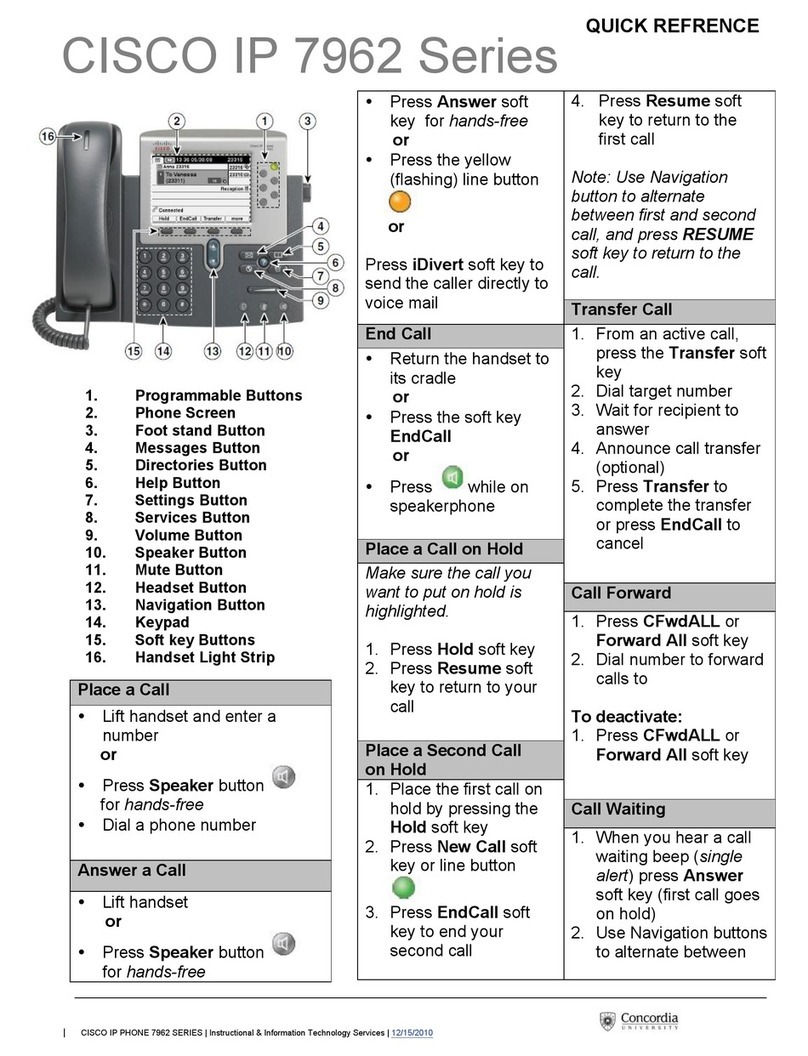
  9. Cisco 8831 Quick reference guide

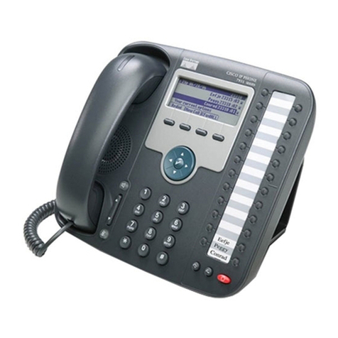
Cisco 8831 Quick reference guide

© 2015 Cisco and/or its affiliates. All rights reserved. This document is Cisco Public Information. Page 1 of 6
Deployment Guide
Cisco Unified IP Conference Phone 8831
Introduction
This deployment guide outlines the best practices for considering a conference room environment with the Cisco®
Unified IP Conference Phone 8831.
This guide is intended primarily for site planning of the Cisco Unified IP Conference Phone 8831. Installers,
network administrators, and facility maintenance personnel may also find this document useful.
Obtaining Documentation and Support, and Developing Security Guidelines
For information about obtaining documentation, submitting a service request, and gathering additional information,
please refer to the monthly “What’s New in Cisco Product Documentation” publication, which also lists all new and
revised Cisco technical documentation, at: http://www.cisco.com/en/US/docs/general/whatsnew/whatsnew.html
Related Documentation
For a complete list of documents for the Cisco Unified IP Conference Phone 8831, please visit the Cisco support
site located at: http://www.cisco.com/cisco/web/support/index.html.
Overview of Cisco Unified IP Conference Phone 8831
The Cisco Unified IP Conference Phone 8831 enhances people-centric communications, combining superior high
definition (HD) audio performance and 360-degree coverage for conference rooms and executive offices. It
provides an audiophile sound experience with a full-duplex two-way wideband (G.722) audio hands-free speaker
(Figure 1).
Figure 1. Cisco Unified IP Conference Phone 8831 with Speakers and Display Control Unit
The Cisco Unified IP Conference Phone 8831 is a simple, scalable solution that meets the challenges of most
conference rooms. It provides flexible deployment expansion by using optional extension microphones that can be
wired or wireless (Digital Equipment Cordless Telephone [DECT]) and has an optional daisy-chain configuration of
two base speaker units.
© 2015 Cisco and/or its affiliates. All rights reserved. This document is Cisco Public Information. Page 2 of 6
As a base kit, the Cisco Unified IP Conference Phone 8831 includes a two-element speaker within the base unit,
as well as four internal microphones located within the corners of the unit. Also included is a corded display control
unit. Depending on your country location, there are six versions of the 8831 base kit (for compliance to country-
specific wireless spectrums).
Table 1. Lists Available Optional 8831 Kits
Optional Kit
Contents
Supported Configurations
Cisco 8831 Wired
Microphone Kit
Includes two wired
microphones
Two wired microphones installed to the primary speaker base unit
If a secondary (daisy-chain) base kit is configured, then one wired microphone is installed to the
primary base and the other wired microphone is installed to the secondary (daisy-chain) base
Cisco 8831
Wireless
Microphone Kit
Includes two wireless
microphones and charger
tray
Two wireless microphones installed to the primary speaker base unit
Note: Wired and wireless kits cannot be installed together
Secondary
(daisy-chain)
Base Kit
Base unit with required
cabling
Only one secondary base kit can be installed per 8831 primary base unit
For more detailed specifications, please refer to the data sheet for the Cisco Unified IP Conference Phone 8831 at:
http://www.cisco.com/c/en/us/products/collateral/collaboration-endpoints/unified-ip-phone-8800-
series/data_sheet_c78-726887.html.
Room Considerations for the Cisco Unified IP Conference Phone 8831
Table 2 lists the maximum recommended room sizes for optimal 8831 audio coverage. Every conference room has
different acoustic characteristics. Conference rooms with high-reverberation acoustics will drastically decrease
these numbers. Acoustic reverberation is caused by hard surfaces such as glass walls and hard-surface flooring. If
you suspect that your conference room has high-reverberation acoustics, then you must test with the 8831 and
optional wired or wireless microphone kits and/or secondary base kit to determine maximum optimal audio
coverage. For best results, testing should be done by adding and subtracting the wired or wireless microphone kit
and/or the secondary base kit. The recommended maximum room sizes in Table 2 assume a rectangular room and
a rectangular table located in the middle with a maximum conference room ceiling height of 10 feet.
Table 2. Maximum Recommended Room Sizes
Supported Configurations
Recommended Maximum Room Size for Optimal
Audio Performance
Power Considerations
Cisco 8831 primary base and display
control unit
20 x 20 ft
400 square feet
IEEE 802.3af Power over Ethernet (PoE) or
Cisco IP Phone Power Cube
Cisco 8831 primary base and display
control unit with two wired microphones
(one wired microphone kit)
20 x 34 ft
680 square feet
Note: The length of the cable for each wired microphone
is 7 feet; therefore, the assumption for this maximum
coverage area is with the wired extension microphones
located 7 feet away from the base. Extension
microphones can be located anywhere from 3 to 7 feet
away from the base
IEEE 802.3af PoE or Cisco Power Cube
© 2015 Cisco and/or its affiliates. All rights reserved. This document is Cisco Public Information. Page 3 of 6
Supported Configurations
Recommended Maximum Room Size for Optimal
Audio Performance
Power Considerations
8831 primary base and display control
unit with two wireless microphones
(one wireless microphone kit)
20 x 40 ft
800 square feet
Note: In order to have full room coverage, meaning a
talker’s voice could be picked up from anywhere within a
20- by 40-foot conference room, the assumption is that
each wireless extension microphone would be placed a
maximum 10 feet away from the base
However, if full talker voice does not need to be evenly
covered across a conference room, wireless
microphones can be placed as far away as 100 feet from
the base. The limiting factor is that the person using the
wireless microphone must be able to hear the sound out
of the 8831 speaker base in order to have an effective
conference call
The primary base and display control unit
can be powered with IEEE 802.3af PoE or by
a Cisco IP Phone Power Cube
The charging tray of the wireless microphone
kit requires commercial AC power. Country
power adapters are available. The AC power
cord is 10 feet long
8831 primary base and display control
unit with a secondary base
20 x 36 feet
720 square feet
Note: The length of the cable between the base units is
18 feet
For the recommended maximum room coverage for this
configuration, the maximum distance between the two
base units is 15 feet. The secondary base provides
additional microphones and more robust sound within
the conference room
The minimum distance between the primary and
secondary base units is 8 feet
The primary base and display control unit
can be powered with IEEE 802.3af PoE or by
a Cisco IP Phone Power Cube
The secondary base kit requires commercial
AC power. Country power adapters are
available. The AC power cord is 10 feet long
8831 primary base and display control
unit with a secondary base and two
wired microphones
20 x 50 feet
1000 square feet
Note: For the recommended maximum room coverage
for this configuration, the maximum distance between the
two base units is 15 feet, and each base unit has one
wired microphone installed 7 feet from the base
The primary base and display control unit
can be powered with IEEE 802.3af PoE or by
a Cisco IP Phone Power Cube
The secondary base kit requires commercial
AC power. Country power adapters are
available. The AC power cord is 10 feet long
8831 primary base and display control
unit with a secondary base and two
wireless microphones
20 x 57 feet
1140 square feet
Note: For the recommended maximum room coverage
for this configuration, the maximum distance between the
two base units is 15 feet, and each base unit has one
wireless microphone installed 10 feet from the base
However, if full talker voice does not need to be evenly
covered across a conference room, wireless
microphones can be placed as far away as 100 feet from
the base. The limiting factor is that the person using the
wireless microphone must be able to hear the sound
from the 8831 speaker base
The primary base and display control unit
can be powered with IEEE 802.3af PoE or by
a Cisco IP Phone Power Cube
The secondary base and wireless
microphone kits require commercial AC
power. Country power adapters are
available. The AC power cords are 10 feet
long
Room Diagram Examples for Optional Coverage
Figure 2 shows the maximum optimal coverage of a 20- by 20-foot room.
Figure 2. Maximum Optimal Coverage of 20- by 20-Foot Room with 8831 Primary Base and Display Control Unit
© 2015 Cisco and/or its affiliates. All rights reserved. This document is Cisco Public Information. Page 4 of 6
Figure 3 shows the maximum optimal coverage of a 20- by 34-foot room.
Figure 3. Maximum Optimal Coverage of 20- by 34-Foot Room with 8831 Primary Base and Display Control Unit with Wired
Microphone Kit
Figure 4 shows maximum optimal coverage of a 20- by 40-foot rectangular room.
Figure 4. Maximum Optimal Coverage of 20- by 40-Foot Rectangular Room with 8831 Primary Base and Display Control Unit
with Wireless Microphone Kit
Figure 5 shows coverage example of U-shaped table configuration.
Figure 5. Coverage Example of U-Shaped Table Configuration with 8831 Primary Base and Display Control Unit with Wireless
Microphone Kit
© 2015 Cisco and/or its affiliates. All rights reserved. This document is Cisco Public Information. Page 5 of 6
Figure 6 shows maximum optimal coverage of a 20- by 36-foot room.
Figure 6. Maximum Optimal Coverage of 20- by 36-Foot Room with 8831 Primary Base and Display Control Unit with

Secondary Base
Figure 7 shows maximum optimal coverage of a 20- by 50-foot conference room.
Figure 7. Maximum Optimal Coverage of 20- by 50-Foot Conference Room with 8831 Primary Base with Display Control Unit,
Secondary Base, and Wired Microphone Kit
Figure 8 shows maximum optimal coverage of a 20- by 57-foot conference room.
Figure 8. Maximum Optimal Coverage of 20- by 57-Foot Conference Room with 8831 Primary Base with Display Control Unit,
Secondary Base, and Wireless Microphone Kit
© 2015 Cisco and/or its affiliates. All rights reserved. This document is Cisco Public Information. Page 6 of 6
Printed in USA C07-734247-00 04/15

Other manuals for 8831

12

Other Cisco IP Phone manuals

Cisco IP 7940 User manual

Cisco

Cisco IP 7940 User manual

Cisco SPA-500 Series User manual

Cisco

Cisco SPA-500 Series User manual

Cisco 7925G - Unified Wireless IP Phone VoIP User manual

Cisco

Cisco 7925G - Unified Wireless IP Phone VoIP User manual

Cisco 8800 Series Quick reference guide

Cisco

Cisco 8800 Series Quick reference guide

Cisco 7965 User manual

Cisco

Cisco 7965 User manual

Cisco Unified 6921 User manual

Cisco

Cisco Unified 6921 User manual

Cisco DATAVOX 7941 User manual

Cisco

Cisco DATAVOX 7941 User manual

Cisco 8941 User manual

Cisco

Cisco 8941 User manual

Cisco 7925G - Unified Wireless IP Phone VoIP User manual

Cisco

Cisco 7925G - Unified Wireless IP Phone VoIP User manual

Cisco DATAVOX 7941 User manual

Cisco

Cisco DATAVOX 7941 User manual

Cisco SPA525G - Small Business Pro IP Phone VoIP User manual

Cisco

Cisco SPA525G - Small Business Pro IP Phone VoIP User manual

Cisco 6800 Series User manual

Cisco

Cisco 6800 Series User manual

Cisco Cisco 7960 Service manual

Cisco

Cisco Cisco 7960 Service manual

Cisco MGCP IP Phone Service manual

Cisco

Cisco MGCP IP Phone Service manual

Cisco 7911 User manual

Cisco

Cisco 7911 User manual

Cisco 7965 User manual

Cisco

Cisco 7965 User manual

Cisco SPA525G - Small Business Pro IP Phone VoIP User manual

Cisco

Cisco SPA525G - Small Business Pro IP Phone VoIP User manual

Cisco CP-7962G User manual

Cisco

Cisco CP-7962G User manual

Cisco Nexus 7000 Series User manual

Cisco

Cisco Nexus 7000 Series User manual

Cisco 8800 Series User manual

Cisco

Cisco 8800 Series User manual

Cisco 8945 Setup guide

Cisco

Cisco 8945 Setup guide

Cisco 8800 Series User manual

Cisco

Cisco 8800 Series User manual

Cisco 7832 User manual

Cisco

Cisco 7832 User manual

Cisco Small Business Pro SPA 509G User manual

Cisco

Cisco Small Business Pro SPA 509G User manual

Popular IP Phone manuals by other brands

ESENE ES410 user manual

ESENE

ESENE ES410 user manual

Telrad Connegy AdvanceIP Avanti 3000ip user guide

Telrad Connegy

Telrad Connegy AdvanceIP Avanti 3000ip user guide

Xorcom UC42 user manual

Xorcom

Xorcom UC42 user manual

Htek UC902S quick reference

Htek

Htek UC902S quick reference

Fanvil C62 user manual

Fanvil

Fanvil C62 user manual

Yealink Telkom W52P quick start guide

Yealink

Yealink Telkom W52P quick start guide

Avaya IP Office 4.2 Installation

Avaya

Avaya IP Office 4.2 Installation

Polycom SoundPoint IP 335 Quick user guide

Polycom

Polycom SoundPoint IP 335 Quick user guide

Polycom VVX-150 Series Quick tips

Polycom

Polycom VVX-150 Series Quick tips

Uniden XDECT SSE27 series owner's manual

Uniden

Uniden XDECT SSE27 series owner's manual

Gigaset A680 instruction manual

Gigaset

Gigaset A680 instruction manual

Genesys Polycom IP 330 quick reference

Genesys

Genesys Polycom IP 330 quick reference

Panasonic KX-TGP600 Quick setup guide

Panasonic

Panasonic KX-TGP600 Quick setup guide

Avaya PARTNER Version 140 Phone user guide

Avaya

Avaya PARTNER Version 140 Phone user guide

Aztech V500DS user manual

Aztech

Aztech V500DS user manual

Yealink Yealink SIP-T42G quick start guide

Yealink

Yealink Yealink SIP-T42G quick start guide

BT RELATE 3000 user guide

BT

BT RELATE 3000 user guide

Yealink SIP-T46U quick start guide

Yealink

Yealink SIP-T46U quick start guide

manuals.online logo
manuals.online logoBrands
  • About & Mission
  • Contact us
  • Privacy Policy
  • Terms and Conditions

Copyright 2025 Manuals.Online. All Rights Reserved.