8
Need help? Visit support.connects2.com/tickets/technical
CTKFT34_IG_v1
9. Attach the antenna adapter in between the vehicles pre-existing connector as well as the rear of the
aftermarket head unit.
NOTE: If vehicles which feature an amplied aerial, the blue wire will be needed for purposes of phantom power.
INSTALLATION GUIDE - WIRING
Before installing the interface, the factory stereo must be removed and disconnected. To do this, please consult the vehicle
owner’s manual/handbook or contact a tting professional.
For universal patch leads, prepare the wiring loops in accordance with the instruction manual supplied before installation.
See Wiring Diagram on Pg.4 for more information
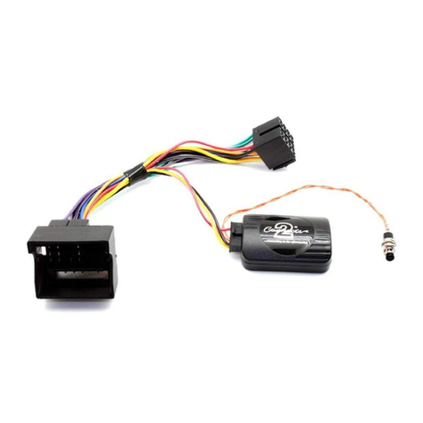
2. Connect the opposite end of the stereo connection (patch) lead to the steering wheel control input on
the back of the aftermarket stereo
NOTE: This may be a 3.5mm jack connector or a wired input depending on the brand of aftermarket stereo being tted. Please consult the
aftermarket stereo installation manual for further information on where to make the connection.
IMPORTANT: THIS STEP MUST BE COMPLETED BEFORE CONNECTING POWER TO THE INTERFACE.
FAILURE TO DO SO MAY RESULT IN A LACK OF FUNCTIONALITY AND THE NEED TO REINSTALL THE PRODUCT
!
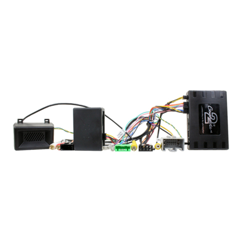
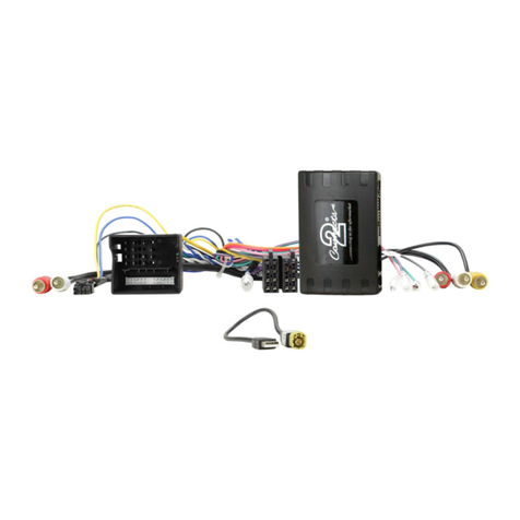
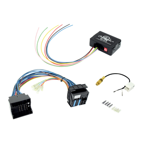
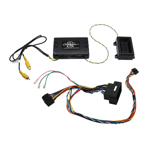
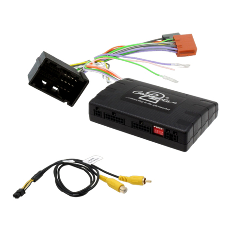
3. Connect the 14 Pin connector from the supplied wiring loom to the interface box.
1. Connect the 12 Pin connector from the stereo connection (patch) lead to the interface box
11. Test stereo and steering wheel control functionality for correct operation before reassembling the
vehicle dashboard. If steering wheel control functions are unresponsive, please uninstall the interface and
wiring and reinstall carefully in accordance with the above steps.
For further help, please contact and ll out a support ticket with the full details of your issue at:
support.connects2.com/tickets/technical
10. Connect the 12 & 32-way connectors on the supplied harness to the relevant connectors from the
vehicle.
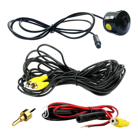
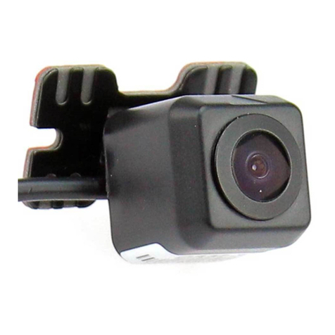
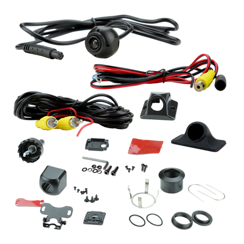
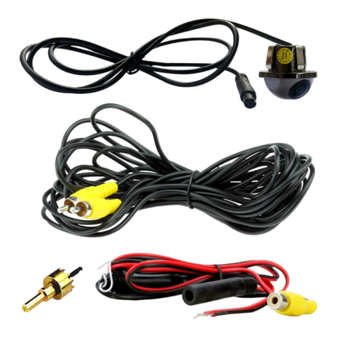
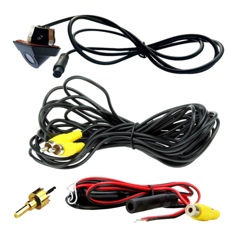
8. To connect an aftermarket reversing camera, connect the female yellow RCA from the camera extension
harness to the male yellow RCA of the camera (optional).
Note: Ensure that the ‘Camera Connected’ option in the Preferences menu is set to ‘Yes’ for the camera to function correctly.
6. Connect any additional outputs from the main wiring harness to the head unit.
For more details surrounding the flying wires, go to Pg.2 and see ‘Additional Connections’.
4. Connect the power/speaker ISO connector to the power/speaker ISO connector at the rear of
aftermarket stereo.
Note: For aftermarket stereos which do not have an ISO connector, please see ‘Wiring Key’ on Pg.2 for information on which wires to connect.
Some interfaces may also have additional ‘flying’ wires which can be connected to the vehicle to support various features i.e. parking brake
trigger, reverse gear and speed pulse. Details of these can be found under ‘Additional Connections’.
5. Connect 4 Pin camera extension harness to the interface box.
7. Connect the male yellow RCA to the reverse camera input of the aftermarket head unit
