manuals.online logo
Brands
  1. Home
  2. •
  3. Brands
  4. •
  5. Dancover
  6. •
  7. Greenhouse Kit
  8. •
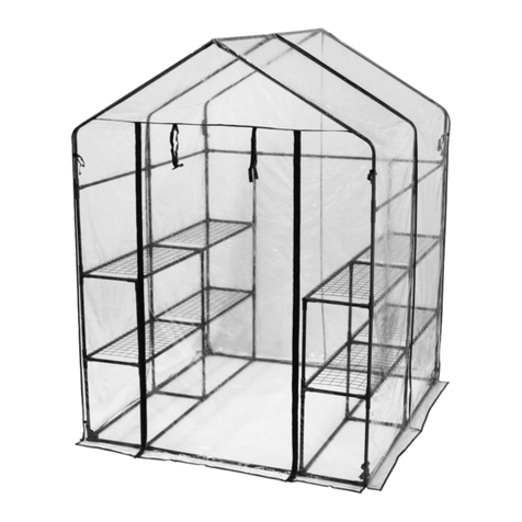
  9. Dancover GH152080 User manual

Dancover GH152080 User manual

for
Greenhouse
2,45x3,04x2,1m
Manual
28-11-2019
Assembly Instructions
PRODUCT SIZE(LxWxH):304X245X210CM
PLEASE READ CAREFULLY BEFORE ASSEMBLY
CONTENTS
KEEP WORKING AREA CLEAN AND DRY
A cluttered, damp or wet working area may cause injuries.
Safety Warning & Advice
PREPARE A FLAT AND LEVEL BASE
Make sure your greenhouse is located on a flat and level surface.
Although this greenhouse is designed to withstand greater wind loads than many other
greenhouses, do not install it in on a windy day or in an area which is subject to high winds.
A partially completed greenhouse may be seriously damaged if it is left in this state. It is
your responsibility to safely and securely anchor the greenhouse, having regard to wind
conditions in your area.
DO NOT INSTALL THE GREENHOUSE ON A WINDY DAY OR
IN AN AREA SUBJECT TO HIGH WINDS
POLYCARBONATE SHEET
Remove approximately 2 inches of film from all sheet edges before installing and remove all film
immediately after the construction is completed. Please ensure that the side with the white film
faces outwards.
CHECK PARTS BEFORE ASSEMBLY
All parts have been well labelled. Please sort, separate and identify all components before
construction and check against the parts list in this manual.
WARNING
Do not install this product when you are tired or distracted from the job at hand. We recommend
that you use gloves during assembly.
POWERED SCREWDRIVER RECOMMENDED
This quality greenhouse features self-tapping screws to provide strong joints. As the name
suggests, the screws tap their own thread. Driving in self-tapping screws requires more force
than conventional screws. A powered screwdriver is therefore recommended.
B1
B1
A1
A1
C
C
C
C
16*S01
1
PART NO QTY
4C 2
A1 2
B1
1
4*S01
C
A1 B1
1
M6X10
S01 16
16
M6
M01
M4.2X16
Z01 36
Base Assembly
Fixing the greenhouse to
the base is recommended.
It is best to do this at
the end, after the
greenhouse has been fully
assembled.
L13
L10
22
L13
2
L13
L13
A1
L10
L10
L10
A1
2 2 2
A1
A1 Z01
Z01
2
L08A
C
C
C
22
L08A
2
L08A
L08A
B1 B1 Z01
Use a powered screwdriver to fix the self-tapping screws (Z01) through the cills (L08A, L10 and L13)
and base plinth (A1 and B1). The screws should be evenly spaced to ensure a neat appearance. The
recommended spacing of the screws is 238mm. You can mark the painted surfaces with a pencil.
PART NO QTY
PART NO QTY
PART NO QTY
2
L01A
1
L10
1
L04A
1L04B
2
L05B
1
L11
2
L03B
6
Y2
2
Y1
Y4
Y5
2
1
2
L01B
6
W01
2
L01A
1
L13
1
L04A
1
L04B
1
L05A
4
L03B
2
L01B
PART NO QTY
1
Y3
2
L08A
PART NO QTY
2
L07
8
L02A
L12A 4
1
L06
6
L02B
1
L02C
1
L03B
9
1
Y7
Y9
10
Y6
2
L09
2
2
2
2
J01
J02L
J02R
J03
1
L14
PART NO QTY
1
W06
1
W04
1
W08
M6X10
S01 48+2
M6
M01 48+2
M4X10
S02 2
M4.2X16
Z01
M4X10
M02 2
182+10
PART NO QTY PART NO QTY
2
L19
1
L21
1
L20
2
L15
2
L17
4
L16
4
L18
1
Y10
2
Y11
4
Y12
1
L03C
1L04C
1
L02D
1
Y8
Y13 1
3
PC/Glass
L21
L19
L20
L19
4*Z01 Y10
2*S02
W06
L21
PART NO QTY
4
M4.2X16
Z01
1
4
Z01
Z01
2
L19
1
L21 1
L20
1
W06
Y10
M4X10
S02 2
M4
M02 2
Vent Assembly
Slide 2 bolts (S02) into the bolt channel (L21)
and fix the handle (W06) in the middle
L18
L18
L16
L16
L17
L15
16*Z01
PART NO QTY
32
M4.2X16
Z01
Y12
Y11
Y12
5
Z01
Z01
Z01
Z01
Z01
Z01
Z01
Z01
Z01
2
L15
2
L17 4
L16
4
L18
2
Y11 4
Y12
Z01
Z01
Z01
Door Assembly
L01A
L10
L04A L04B L01A
12
21
L01A
L10
L04A L04B
34
L01A
PART NO QTY
2
L01A 1
L10 4
M4.2X16
Z01
1
L04A 1L04B
6
1
L10
L01A
L10
L01A
2
3
L04A
4
L04B
L01A
1. Lay out the glazing bars (2 x L01A, L04A and L04B) and the
cill (L10). Ensure that the cill upstand is on the inside
and that L01A is the correct way round.
2. Make a pencil mark on the glazing bars (2 x L01A, L04A and
L04B) at a height of 1059mm from the bottom. This will help
later when fitting part L05B.
3. Fix the glazing bars (2 x L01A, L04A and L04B) to the cill
(L10) with the self-tapping screws (Z01) using a powered
screwdriver. The inside of the glazing bars feature guide
lines which indicate the correct screw positions (see detail
drawings below). Be careful to ensure that the screws are
in the correct position (see detail drawings below).
Screw
position Screw
position
Screw
position Screw
position
Screw
position Screw
position
1059MM
21
L05B
L05B
Z01
Z01
L11
L11
3*S01
L11
3*S01
L05B L05B
3456
L11 L11
1221
56
L01A
7
L04A L04B L01A
L04A/B
L05B
L01A
2
L05B 8
M4.2X16
Z01
1
L11
PART NO QTY
M6X10
S01 6
M6
M01 2
1. Fix 1 x L05B to L01A and L04A and 1 x L05B to L04B and L01A with the self-tapping screws (Z01)
using a powered screwdriver. Ensure that L05B is fixed at a right angle (90 degrees) to the
glazing bars (2 x L01A, L04A and L04B).
2. Slide 3 bolts (S01) into the inside L11 bolt channel and fix L11 to L04A and L04B (see Figure 4,
Figure 5 and Figure 6). Slide 3 bolts (S01) into the external L11 bolt channel (see Figure 3).
This will help later when fitting part L14.
3. Part W02 is factory fitted to glazing bars L04A and L04B.
Screw
position
1059MM
L03C
W04
L11
Y2
L03B
1111
Y2
8
L11 L04B
W04
1
L03B
2*S01
L05B
S01 L03B
L03C
S01
S01
1W04
1
Y1
Y4
Y5 1
1
PART NO QTY
2
L03B
2
Y2
M6X10
S01 6
M6
M01 6
Y5
Y4
Y13
1
L03C
Y13 1
W04 1
1
Y1
1. Slide the lower glazing panels (Y2) into position.
2. Slide 2 bolts (S01) into the inside L03B bolt channel and fix L03B to L05B.
3. Make a pencil mark on L11 at a distance of 594mm from the right. Fix the plate (W04) using
the extra S01 bolt placed in the bolt channel earlier.
4. Slide 2 bolts (S01) into L03C bolt channel. One is used to fix W04 and the other wil be
used later to fix W01.
5. Slide the higher glazing panels (Y1, Y4, Y5 and Y13) into position.
2
3
1
2
3
L01B L01B
W01 W01
W01
9
L01A L01A
PART NO QTY
2
L01B 16
M4.2X16
Z01
3
W01
M6
M01 1
L01B
1
2
3
W01
W01
4*Z01
L01B
Z01
L01B 2
Z01
L01B
2*Z01
L01B
3
2*Z01 L01B
W01
L01A/L01B
M01
Front Wall
Fix 1 x L01B to L01A and L04A and 1 x L01B to
L04B and L01A using the W01 angled plates fixed
with self-tapping screws (Z01) using a powered
screwdriver. The inside of the glazing bars
feature guide lines which indicate the correct
screw positions (see detail drawings below).
Be careful to ensure that the screws are in
the correct position (see detail drawings below).
L04A L04B
Screw
position
L04C
3
L04C
1
L13 L01A
L13
L04A L04B L01A
12
21
L01A
L13
L04A L04B
34
L01A
PART NO QTY
2
L01A
5
M4.2X16
Z01
1
L04A 1L04B
10
1
L10
L01A
L10
L01A
2
L04A&B&C
L01A
1
L04C
1. Lay out the glazing bars (2 x L01A, L04A, L04B and L04C)
and the cill (L13). Ensure that the cill upstand is on
the inside and that L01A is the correct way round.
2. Make a pencil mark on the glazing bars (2 x L01A, L04A,
L04B and L04C) at a height of 1059mm from the bottom.
This will help later when fitting part L05A.
3. Fix the glazing bars (2 x L01A, L04A, L04B and L04C) to
the cill (L13) with the self-tapping screws (Z01) using
a powered screwdriver. The inside of the glazing bars
feature guide lines which indicate the correct screw positions
(see detail drawings below). Be careful to ensure that the
screws are in the correct position (see detail drawings below).
screw
position
screw
position
screw
position screw
position
screw
position
1059MM
1 1
L05A
Z01
Z01
L05A 2-4
L05A
12341
Y2 Y2 Y2 Y2
11
L01A L04A L04C L01B L01A
L05A
L04A/B/C
L01A
PART NO QTY
4
Y2
1
L05A
10
M4.2X16
Z01
1. Fix the horizontal brace (L05A) to the glazing bars (2 x L01A, L04A, L04B and L04C) with the
self-tapping screws (Z01) using a powered screwdriver. Ensure that L05A is fixed at a right
angle (90 degrees) to the glazing bars.
2. Slide the lower glazing panels (Y2) into position.
screw
position Screw
position
1059MM
PART NO QTY
4
L03B
Y5 Y3 Y13
Y8
1
1
Y5
Y13 1
1
Y3
Y8
1L03B
11 11 11 1
12
M6X10
S01 8
M6
M01 8
L05A
S01 L03B
L03B
2*S01
1. Slide 2 bolts (S01) into the inside L03B bolt channel and fix L03B to L05A.
2. Slide the higher glazing panels (Y3, Y5, Y8 and Y13) into position.
2
3
1
2
3
W01 W01
W01
PART NO QTY
2L01B 17
M4.2X16
Z01
3
W01 L01B L01B
13
L01B
1
2
3
W01
W01
5*Z01
L01B
L01B
2
L01B
L01B 3
L01B
W01
L01A/B
Rear Wall
1. Fix 1 x L01B to L01A and L04A and 1 x L01B to L04B
and L01A using the W01 angled plates fixed with
self-tapping screws (Z01) using a powered
screwdriver. The inside of the glazing bars feature
guide lines which indicate the correct screw
positions (see detail drawings below). Be careful to
ensure that the screws are in the correct position
(see detail drawings below).
2. Part W02 is factory fitted to glazing bars L04A and L04B.
W02
4*Z01 4*Z01
2*Z01 2*Z01
Screw
position
2
L08A
PART NO QTY
L08A
L08A
3*S01
L01A
1
L01A L01A
L08A
1
1
M6X10
S01 12
M6
M01 4
14
1. Slide 3 bolts (S01) into each L01A bolt
channel (2 to be used later).
2. Bolt 2 x L08A cills to L01A using S01 bolts
Screw
Position
Front
Rear
2
L07
PART NO QTY
15
3*S01
L01B
L01A
L01BL07
1
L01A
L01B
L07
2
1
1
2
2
L07
L07
L01B
L01B
L01A
L01A
M6X10
S01 12
M6
M01 8
Slide 3 bolts (S01) into each L01B bolt channel (2 to be used later).
Bolt 2 x L07 eaves to L01A and L01B using S01 bolts
L02A
8
L02A
M4.2X16
Z01
2
L02A
2
22
111
PART NO QTY
16
16
2
L02A
1
L02A
1
Fix the glazing bars (L02A) to the cills (L08A) and the eaves (L07) with the self-tapping screws
(Z01) using a powered screwdriver. The inside of the glazing bars feature guide lines which
indicate the correct screw positions (see detail drawings below). Be careful to ensure that the
screws are in the correct position (see detail drawings below).
screw position

This manual suits for next models

4

Other Dancover Greenhouse Kit manuals

Dancover Louver Wall User manual

Dancover

Dancover Louver Wall User manual

Dancover TITAN Classic User manual

Dancover

Dancover TITAN Classic User manual

Dancover GH152015 User manual

Dancover

Dancover GH152015 User manual

Dancover GH152180 User manual

Dancover

Dancover GH152180 User manual

Dancover Polytunnel Greenhouse 4m Series User manual

Dancover

Dancover Polytunnel Greenhouse 4m Series User manual

Dancover STRONG Series User manual

Dancover

Dancover STRONG Series User manual

Dancover GH152190 User manual

Dancover

Dancover GH152190 User manual

Dancover GH152190 User manual

Dancover

Dancover GH152190 User manual

Dancover GH97200 User manual

Dancover

Dancover GH97200 User manual

Dancover GH152200 User manual

Dancover

Dancover GH152200 User manual

Dancover Polytunnel Greenhouse 3x8m User manual

Dancover

Dancover Polytunnel Greenhouse 3x8m User manual

Dancover DUO User manual

Dancover

Dancover DUO User manual

Dancover gh21200 User manual

Dancover

Dancover gh21200 User manual

Dancover TITAN Peak 240 5,0 User manual

Dancover

Dancover TITAN Peak 240 5,0 User manual

Dancover GH82121 User manual

Dancover

Dancover GH82121 User manual

Dancover TITAN Dome 320 User manual

Dancover

Dancover TITAN Dome 320 User manual

Dancover ARROW 3m Series User manual

Dancover

Dancover ARROW 3m Series User manual

Dancover GH158011 User manual

Dancover

Dancover GH158011 User manual

Dancover ASTRA GH120150 User manual

Dancover

Dancover ASTRA GH120150 User manual

Dancover Polytunnel Greenhouse 3x6m User manual

Dancover

Dancover Polytunnel Greenhouse 3x6m User manual

Dancover GH152100 User manual

Dancover

Dancover GH152100 User manual

Dancover GH82020 User manual

Dancover

Dancover GH82020 User manual

Dancover Polytunnel Greenhouse User manual

Dancover

Dancover Polytunnel Greenhouse User manual

Dancover ARROW GH120025 User manual

Dancover

Dancover ARROW GH120025 User manual

Popular Greenhouse Kit manuals by other brands

Halls Greenhouses Magnum 108 Assembly instructions

Halls Greenhouses

Halls Greenhouses Magnum 108 Assembly instructions

Zip Tie Domes 2V Assembly manual

Zip Tie Domes

Zip Tie Domes 2V Assembly manual

Mercia Garden Products 04GREENLEAN0804-V2 Assembly instructions

Mercia Garden Products

Mercia Garden Products 04GREENLEAN0804-V2 Assembly instructions

Palram Applications Grand Gardener Prestige 8x8 instructions

Palram Applications

Palram Applications Grand Gardener Prestige 8x8 instructions

Sun Hut 706925 installation instructions

Sun Hut

Sun Hut 706925 installation instructions

Otto VM9057-PSC 5000 Assembly instructions

Otto

Otto VM9057-PSC 5000 Assembly instructions

Juliana Basic 300 manual

Juliana

Juliana Basic 300 manual

COVERTECH Amber Assembly manual

COVERTECH

COVERTECH Amber Assembly manual

Grandio GRA-88BR-GR user manual

Grandio

Grandio GRA-88BR-GR user manual

Gainsborough K164 Assembly instructions/Instructions for use

Gainsborough

Gainsborough K164 Assembly instructions/Instructions for use

GrowSpan 108197H manual

GrowSpan

GrowSpan 108197H manual

GrowSpan 500 Series manual

GrowSpan

GrowSpan 500 Series manual

Bio Green PATIOFLORA 100 Assembly instructions

Bio Green

Bio Green PATIOFLORA 100 Assembly instructions

Johnny's Selected Seeds Quick Hoops 7617 instruction manual

Johnny's Selected Seeds

Johnny's Selected Seeds Quick Hoops 7617 instruction manual

GrowSpan 117149 manual

GrowSpan

GrowSpan 117149 manual

Halls Greenhouses Universal 128 SD manual

Halls Greenhouses

Halls Greenhouses Universal 128 SD manual

FarmTek Aquaponics System I Series manual

FarmTek

FarmTek Aquaponics System I Series manual

Alton EVOLUTION TWELVE CEDAR PARTITION instruction manual

Alton

Alton EVOLUTION TWELVE CEDAR PARTITION instruction manual

manuals.online logo
manuals.online logoBrands
  • About & Mission
  • Contact us
  • Privacy Policy
  • Terms and Conditions

Copyright 2025 Manuals.Online. All Rights Reserved.