manuals.online logo
Brands
  1. Home
  2. •
  3. Brands
  4. •
  5. DANLERS
  6. •
  7. Switch
  8. •
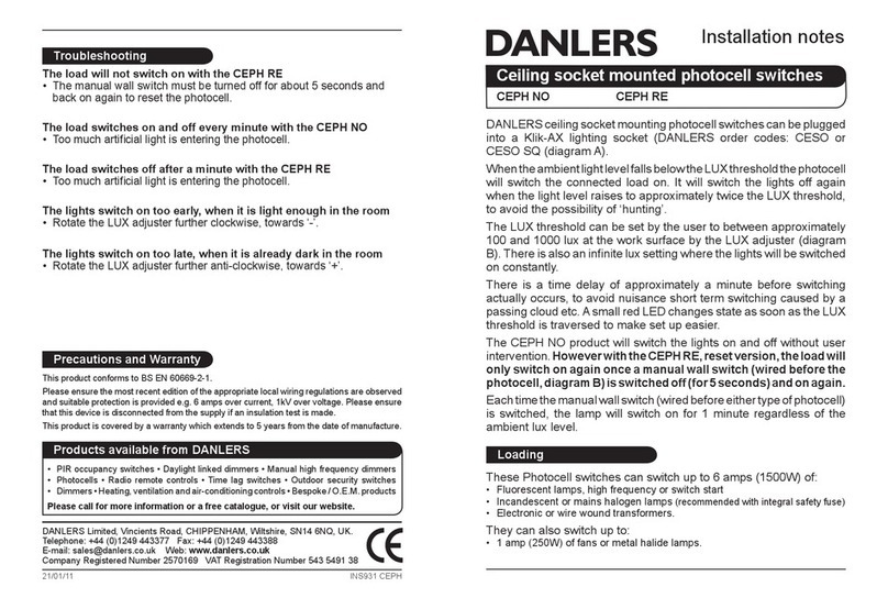
  9. DANLERS CZ HB ND Quick start guide

DANLERS CZ HB ND Quick start guide

Installation notes
DANLERS Limited, Vincients Road, CHIPPENHAM, Wiltshire, SN14 6NQ, UK.
Telephone: +44 (0)1249 443377 Fax: +44 (0)1249 443388
E-mail: [email protected] Web: www.danlers.co.uk
Company Registered Number 2570169 VAT Registration Number 543 5491 38
Products available from DANLERS
• PIR occupancy switches • Daylight linked dimmers • Manual high frequency dimmers
• Photocells • Radio remote controls • Time lag switches • Outdoor security switches
• Dimmers • Heating, ventilation and air-conditioning controls • Bespoke / O.E.M. products
Please call for more information or a free catalogue, or visit our website.
This product conforms to BS EN 60669-2-1, BS EN 55015 and BS EN 60730.
Please ensure the most recent edition of the appropriate local wiring regulations are observed
and suitable protection is provided (protected with the appropriate MCB) 1kV over voltage.
Please ensure that this device is disconnected from the supply if an insulation test is made.
This product is covered by a warranty which extends to 5 years from the date of manufacture.
Precautions and Warranty
Variants
DANLERS design and manufacture other ControlZAPP High bay mounted variants,
coded by the following order codes:
CZ HB (xx) 10VDC Suitable for 1-10VDC ballasts
CZ HB (xx) DALI Suitable for DALI ballasts
Troubleshooting
The load will not switch on:
•TheLUXsettingasspeciedbytheControlZAPPAppissettoolowandis
inhibiting the switch.
• The moving body is not emitting more IR than the background.
(Person wearing insulating clothing in a warm environment)
• Person is too far from the PIR switch, see detection diagram.
• Person is moving unusually slowly (perhaps when testing).
• The control unit battery is not engaged (ON).
Switch RED dip switch next to the telejack connector on the CZ HB (xx)
control unit towards the centre of the control (see diagram E).
The load switches on when nobody is present:
• Heater causing infra-red variations in a small cold room.
Resite the control away from heater.
• Please contact DANLERS for further technical support.
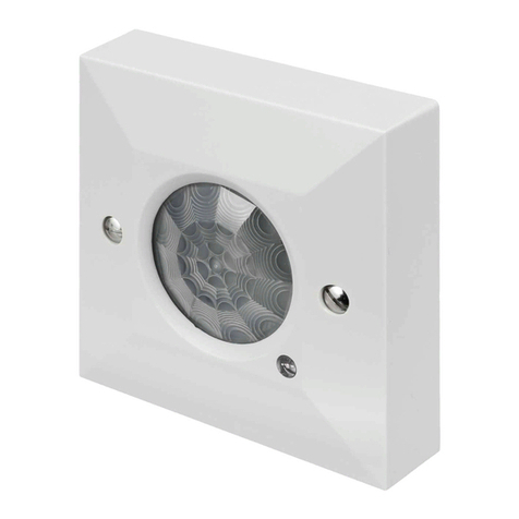
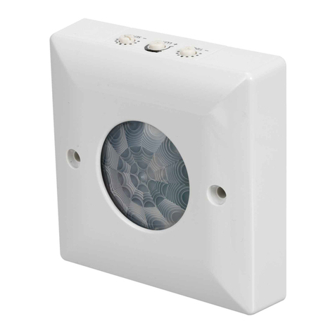
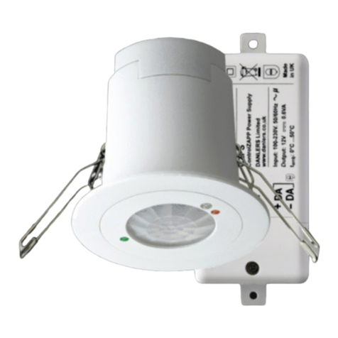
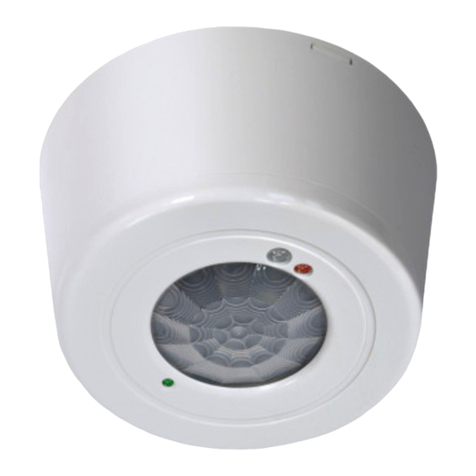
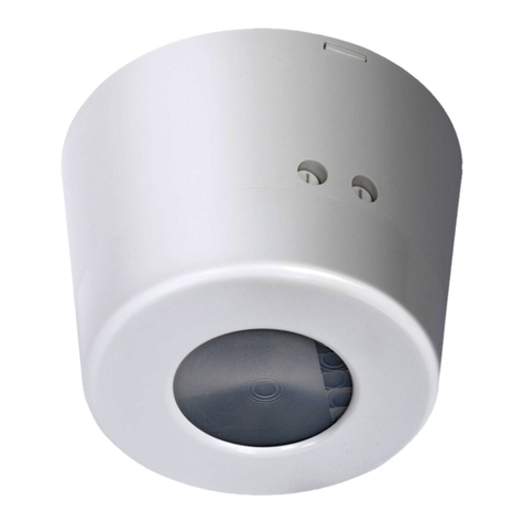
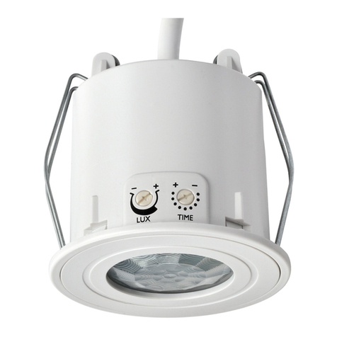
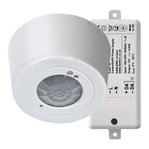
ControlZAPP high bay passive infra-red occupancy switches can be mounted directly
onto solid ceilings or onto a range of different mounting boxes (diagram A).
ControlZAPP devices incorporate a passive infra-red quad sensor to detect movement
of a warm body within their detection zone (diagram B) and a photocell to monitor the
ambient light level.
ALL adjustments are made via a freely downloadable ControlZAPPApp available
from the DANLERS website.
If the ControlZAPP device is set as PIR with LUX input, upon detecting movement, if
the ambient light is dark enough, the ControlZAPP device will turn the load ON. The
ambientthresholdcanbesettobetweenapproximately30luxto1000luxandinnite
lux (photocell inactive) via the ‘Respond to Daylight’ settings on the ControlZAPP App.
If no more movement is detected within a pre-selected time as determined by the
ControlZAPP App, then the ControlZAPP device will turn the load off. This ‘Time Off
Timeout’ or time lag can be set via the ControlZAPP App adjuster between 10sec
and 23hrs 59min 59sec.
These high bay controls are available in three types - each with a particular
detection pattern which is optimised for particular applications.
CZ HB ND: Narrow Detection version is ideal for covering storage aisles.
CZ HB SP: Spot Detection version is ideal for smaller areas,
such as the entrances to storage aisles.
CZ HB WD: Wide Detection version is ideal for large open areas,
such as factories, sports halls and entrance halls.
Loading
These controls are suitable for mains switching or DALI switching only.
They can also switch up to:
• 10 amps (3000W) of resistive loads
• 6amps(1500W)uorescentlamps,highfrequencyorswitchstart,
incandescent or mains halogen lamps (recommended with integral safety fuse)
• 3 amps (750W) of electronic or wire wound transformers.
• 2 amps (500W) of low energy lamps: CFL, LED, 2D etc.
• 1 amp (250W) of fans or most metal halide lamps.
Start-up and default settings
When the control is powered up, it will take 1 minute for the circuitry to stabilise (detection
LEDashing)andensuretheoutputisoff,theControlZAPPdevicewillthenenterits
Default Operating Mode.
Please Note: When in the Default Operating Mode the control is set up as an occupancy
switch with a 20 minute turn OFF timeout (time lag) and photocell disabled.
ControlZAPP High bay controls
CZ HB ND CZ HB SP CZ HB WD
15/09/16 INS314 CZ HB (xx)
Installation procedure
1. Please read these notes carefully before commencing work. In case of doubt please
consultaqualiedelectrician.Ensurewiresandcablesaresecurelyheldwithinthe
connection terminals.
IMPORTANT: The CZ HB (xx) Control Unit clock battery must be engaged (ON)
prior to installation by switching the RED dip switch (see diagram E) to the
DOWN position.
2. POSITIONING: The CZ HB (xx) switch should be installed to achieve correct
coverage of the area, see diagram B. If the photocell override facility (enabled via
ControlZAPP app) is required, the switch must be located above an area where
daylightcangivegreaterilluminationthanthearticiallight.Avoidlocatingthis
product where it is exposed to drafty conditions (exposed lobbies, open ceiling
voids or near fans) or near heat sources.
3. Disconnect the PIR from the circuit before performing insulation testing of the wiring
circuit.
4. Do not connect on a circuit with large inductive loads, as induced spikes may cause
false triggering or damage the PIR.
5. CZ HB (xx) must be connected to the ControlZAPP Power Supply (CZPS) via the
ControlZAPP communication cable (telejack) provided, for wiring see diagrams C
and D. NOTE: The use of non ControlZAPP connectors may damage the CZ CESR
or CZPS and will invalidate the warranty).
6. Knockout or drill the appropriate holes on the mounting plate for attaching the plate
to the ceiling or back box (if applicable). Feed telejack through the appropriate (side
or rear) entry hole. Screw the back mounting plate to the ceiling or back box via the
mounting holes. Push the telejack connector into the sensor head terminal. Push the
sensor head onto the mounting plate and align the side clips with the slots on the
sensor heads
Settings and calibration
NOTE: ALL settings are adjusted by ControlZAPP App as specied in the
ControlZAPP App User Guide (downloadable from the DANLERS website)
including: MODE settings, SCHEDULER settings and photocell settings and
intelligent photocell calibration procedure.
MODE settings include: Detect Movement (enable or disable), Sensitivity, Short Visit
Mode (with timer), Turn ON automatically (Presence detection or Absence detection),
Turn OFF timeout (from10sec to 23hrs 59min 59sec), Respond to Daylight (enabled
or disabled) the calibration process must be run for the intelligent photocell to work.
Delay before ON or Delay before OFF timers, Scene Recall (ON or OFF).
SCHEDULER settings include:
DAY TYPES(deningtimesforeachoftheModestooccur).
WEEKLY SCHEDULE(deningwhichDayTypesareassignedtodifferentdaysofthe
week).
EXCEPTIONS(deningexceptionstotheschedule).
VIEW ON CALENDAR (overview of what and when Modes happen).
Telejack connector
Control Unit
SL
L
L
N
Power Supply
Red dip switch (MUST be
switched towards centre of control)
to engage clock battery ON
IMPORTANT
ON
E: Connector diagram
Up to 5m
diameter
Up to 3m
NARROW
DETECTION (ND)
Mounting height
up to 12m
Perspective view -
ceiling mounted
Up
to
15m
SPOT
DETECTION (SP)
Mounting height
up to 20m
Perspective view -
ceiling mounted
Up to 28m
diameter
WIDE
DETECTION (WD)
Mounting height
up to 14m
Perspective view -
ceiling mounted
A: Detection diagrams
D: Mounting plate xing
L
load
N
L
N
SL
load
L
N
L
N
SL
L
N
SL
L
N
SL
100-260 VAC
50 / 60 Hz
100-260 VAC
50 / 60 Hz
B: Wiring diagram, single PIR C: Wiring diagram, multiple PIRs
L
load
N
L
N
SL
load
L
N
L
N
SL
L
N
SL
L
N
SL
100-260 VAC
50 / 60 Hz
100-260 VAC
50 / 60 Hz
Knock out mounting
holes or pre-drill
pilot holes.
For telejack entry from
above - knock out
central mounting hole
For side entry -
knock out side
mounting hole
Clip telejack into the device
then join device to mounting
plate via mounting clips

This manual suits for next models

2

Other DANLERS Switch manuals

DANLERS ControlZAPP CZ CEFL DALI Quick start guide

DANLERS

DANLERS ControlZAPP CZ CEFL DALI Quick start guide

DANLERS CESRA PIR 10VDC Quick start guide

DANLERS

DANLERS CESRA PIR 10VDC Quick start guide

DANLERS EasyZAPP EZ CEFL Quick start guide

DANLERS

DANLERS EasyZAPP EZ CEFL Quick start guide

DANLERS CZ CEFL Quick start guide

DANLERS

DANLERS CZ CEFL Quick start guide

DANLERS CESRAPIRSD Quick start guide

DANLERS

DANLERS CESRAPIRSD Quick start guide

DANLERS CESRA PIR DSIP Quick start guide

DANLERS

DANLERS CESRA PIR DSIP Quick start guide

DANLERS CEFLAPIR Quick start guide

DANLERS

DANLERS CEFLAPIR Quick start guide

DANLERS TLSW HB Quick start guide

DANLERS

DANLERS TLSW HB Quick start guide

DANLERS CESF PIR User manual

DANLERS

DANLERS CESF PIR User manual

DANLERS WACE RFS Quick start guide

DANLERS

DANLERS WACE RFS Quick start guide

DANLERS CESFPIRSV Quick start guide

DANLERS

DANLERS CESFPIRSV Quick start guide

DANLERS TWSW Quick start guide

DANLERS

DANLERS TWSW Quick start guide

DANLERS ControlZAPP CZ CESR 10VDC Quick start guide

DANLERS

DANLERS ControlZAPP CZ CESR 10VDC Quick start guide

DANLERS TLSW A20 Quick start guide

DANLERS

DANLERS TLSW A20 Quick start guide

DANLERS COPIR IP66 User manual

DANLERS

DANLERS COPIR IP66 User manual

DANLERS TLSW 10 ILM Quick start guide

DANLERS

DANLERS TLSW 10 ILM Quick start guide

DANLERS DUSW Quick start guide

DANLERS

DANLERS DUSW Quick start guide

DANLERS TLSW HB Quick start guide

DANLERS

DANLERS TLSW HB Quick start guide

DANLERS ControlZAPP CZ CEFL 10VDC Quick start guide

DANLERS

DANLERS ControlZAPP CZ CEFL 10VDC Quick start guide

DANLERS CEFLA PIR DALIP Quick start guide

DANLERS

DANLERS CEFLA PIR DALIP Quick start guide

DANLERS WACEPIR Quick start guide

DANLERS

DANLERS WACEPIR Quick start guide

DANLERS CESF PIR Quick start guide

DANLERS

DANLERS CESF PIR Quick start guide

DANLERS WAPIR Quick start guide

DANLERS

DANLERS WAPIR Quick start guide

DANLERS BMPIR10M Quick start guide

DANLERS

DANLERS BMPIR10M Quick start guide

Popular Switch manuals by other brands

Omega Engineering LVH-200 Series user guide

Omega Engineering

Omega Engineering LVH-200 Series user guide

HP A10500 Series installation guide

HP

HP A10500 Series installation guide

Dell PowerConnect 5424 Getting started guide

Dell

Dell PowerConnect 5424 Getting started guide

Belden HIRSCHMANN IT MAMMUTHUS MTS2948X-6Q-A user manual

Belden

Belden HIRSCHMANN IT MAMMUTHUS MTS2948X-6Q-A user manual

Endress+Hauser Liquiphant M FTL50 operating instructions

Endress+Hauser

Endress+Hauser Liquiphant M FTL50 operating instructions

D-Link DGS-1005G Quick install guide

D-Link

D-Link DGS-1005G Quick install guide

DATREND Systems vPad-A1 operating manual

DATREND Systems

DATREND Systems vPad-A1 operating manual

NetComm NCT240 installation guide

NetComm

NetComm NCT240 installation guide

eao 04 Series Assembly instructions

eao

eao 04 Series Assembly instructions

ESYLUX CU-DIN KNK Series user manual

ESYLUX

ESYLUX CU-DIN KNK Series user manual

Winegard VS-0604 manual

Winegard

Winegard VS-0604 manual

Linksys FENSK05 - EtherFast Network Starter user guide

Linksys

Linksys FENSK05 - EtherFast Network Starter user guide

schmersal AZ201 operating instructions

schmersal

schmersal AZ201 operating instructions

LONG-JOIN JL-403C manual

LONG-JOIN

LONG-JOIN JL-403C manual

Asante NetStacker II user manual

Asante

Asante NetStacker II user manual

BODYGUARDZ Portable 5-in-1 Emergency Hub user guide

BODYGUARDZ

BODYGUARDZ Portable 5-in-1 Emergency Hub user guide

Intermatic ET1700 Series Installation and user instructions

Intermatic

Intermatic ET1700 Series Installation and user instructions

Siemens RUGGEDCOM M969F installation guide

Siemens

Siemens RUGGEDCOM M969F installation guide

manuals.online logo
manuals.online logoBrands
  • About & Mission
  • Contact us
  • Privacy Policy
  • Terms and Conditions

Copyright 2025 Manuals.Online. All Rights Reserved.