manuals.online logo
Brands
  1. Home
  2. •
  3. Brands
  4. •
  5. Di-soric
  6. •
  7. Accessories
  8. •
  9. Di-soric US 46 Series User manual

Di-soric US 46 Series User manual

Betriebsanleitung / Operating instructions
Ultraschall-Sensoren / Ultrasonic sensors
US 46 ... B 07/2.1105de
iEine große Oberfläche des zu erfassen-
den Objektes erhöht die Schaltsicher-
heit.
iObjekte mit glatter Oberfläche können
bis zu einem Neigungswinkel von ca.
7° (US 46 K 150 ...) bzw. 10° (US 46 K
500 ...) erkannt werden. Raue und
stark strukturierte Objekte sind mit
größeren Neigungswinkeln erfassbar.
Physikalische Anwendungsgrenzen
- Ultraschall-Sensoren sind aus physikali-
schen Gründen (Schallgeschwindigkeit in
Luft 341 m/s bei 20 °C) relativ langsam.
- Aufgrund der Ultraschallfrequenz er-
rechnet sich eine Auflösung von
± 1,8 mm bei 175 kHz (US 46 K 500 ...)
bzw. ± 1,0 mm bei 350 kHz
(US 46 K 150 ...).
- Keine Funktion unter Wasser, in Vakuum
und bei größeren Überdrücken.
- Sehr heiße (> +100 °C) oder sehr kalte
Objekte (< -10 °C) können u. U. nicht
abgetastet werden (Turbulenzen der Luft
mit Brechung und Streuung des Schalls).
- Starke Luftströmungen > 20 m/s kön-
nen die Abtastsicherheit verringern.
- Eisbildung auf der Wandleroberfläche
reduziert die Empfindlichkeit des Sen-
sors (Abhilfe durch Auftragen einer
dünnen Schicht Silikonfett auf die
Wandleroberfläche).
- Sehr kleine oder sehr schlecht reflektie-
rende (schallabsorbierende) Objekte
können u. U. nicht bis zum Grenzab-
stand erfasst werden. Schallabsorbieren-
de Materialien sind z.B. Schaumgummi,
lose Baumwolle, Filz, Textilien, ausgasen-
de Flüssigkeiten, rutschender Sand usw.
- Bei zu großer Neigung des zu erfassen-
den Objektes zur Strahlachse wird nicht
mehr genügend Schall in Empfänger-
richtung reflektiert (besonders bei
größeren, ebenen Flächen). Glatte
Objekte können bis zu einer Neigung
von 10° sicher detektiert werden. Rauhe
Oberflächen unter Umständen bis 60°
oder mehr.
Montage
iUm eine einwandfreie Funktion der
Ultraschall-Sensoren US 46 ... zu ge-
währleisten, müssen die mit dem
Montagematerial gelieferten Gummi-
unter-/zwischenlagen unbedingt ver-
wendet werden.
iStarke Fremdschallquellen in der Schall-
achse von Ultraschall-Sensoren sind zu
vermeiden.
iBeim Einbau in Rohre muss der Rohr-
durchmesser größer als der Schallkeu-
lendurchmesser sein (siehe Abtastfel-
der). Das Verhalten des Ultraschall-
Sensors muss durch Versuche ermittelt
werden.
iNie die Schallachsen von Geräten der
gleichen Baureihe aufeinander richten.
Die Montage erfolgt mit Gummizwischen-
lagen über das Gehäusegewinde.
Bestimmungsgemäßer Gebrauch
Ultraschall-Sensoren US... werden als Be-
standteil eines übergeordneten Gesamt-
systems zum Erfassen von Objekten ein-
gesetzt.
-Konformität
EMV-Richtlinie DIN EN 60947-5-2
Niederspannungs- 73/23/EWG
richtlinie 93/68/EWG
Sicherheitshinweise
Ultraschall-Sensoren US... sind nicht
zulässig für Sicherheitsanwendungen,
insbesondere bei denen die Sicherheit
von Personen von der Gerätefunktion
abhängig ist.
Ultraschall-Sensoren dürfen nicht in
explosionsgefährdeten Räumen betrie-
ben werden.
Der Betreiber des übergeordneten
Gesamtsystems, z.B. einer Maschinen-
anlage, ist für die Einhaltung der für den
speziellen Einsatzfall geltenden nationa-
len und internationalen Sicherheits- und
Unfallverhütungsvorschriften verant-
wortlich.
Bei Maschinenplanung und Verwen-
dung der Ultraschall-Sensoren US... sind
die einsatzspezifischen Sicherheits- und
Unfallverhütungsvorschriften einzuhal-
ten, wie z.B.:
- EN 60204, Elektrische Ausrüstung von
Maschinen
- EN 292, Sicherheit von Maschinen,
allgemeine Gestaltungsleitsätze
- DIN 57100 Teil 410, Schutz gegen
gefährliche Körperströme
Montage und elektrischer Anschluss der
Ultraschall-Sensoren US... darf nur von
Fachpersonal nach geltenden Vorschrif-
ten in spannungsfreiem Zustand und
bei ausgeschalteter Maschine erfol-
gen.
Die Maschine muss gegen Wieder-
einschalten gesichert sein.
Funktion
Ultraschall-Sensoren US... senden mittels
eines Ultraschallwandlers Schallwellen
einer bestimmten Frequenz über das
Übertragungsmedium Luft aus. Das
Senden der Schallwellen erfolgt in zeitlich
begrenzten Takten. Derselbe Ultraschall-
wandler dient in den Sendepausen als
Schallempfänger mit ausgeprägter Richt-
charakteristik. Das Abtastfeld ist keulen-
förmig und relativ schmal. Durch eine
Laufzeitmessung werden die in den
Sendepausen vom Zielobjekt reflektierten
Schallwellen als Echos im Gerät verarbeitet
und daraus ein abstandsproportionales
Ausgangssignal gebildet.
Der Schaltausgang (Transistorausgang
pnp) des Gerätes wird dann aktiv, wenn
ein abgetastetes Objekt einen am Potenti-
ometer voreingestellten Abstandswert
unterschreitet.
Der Sensor US 46 K 150 ... verfügt über
eine einstellbare Hysterese. Durch die
einstellbare Hysterese lässt sich z.B. auch
eine Min./Max.-Niveauüberwachung
realisieren.
Beim Sensor US 46 K 500 ... lässt sich eine
Impulsverlängerung von 0,4 s bis 8 s
einstellen.
!Verwenden Sie zum Einstellen der
Potentiometer unbedingt den mitgelie-
ferten Miniaturschraubendreher. Die
Verwendung eines ungeeigneten
Werkzeugs kann zur Beschädigung des
Sensors führen.
iBei Raumtemperatur können praktisch
alle Objekte innerhalb des Arbeitsberei-
ches des Sensors erfasst werden.
Authorized use
Ultrasonic sensors US... are used as a
part of a higher-level overall system for
detection of objects.
conformity
EMV directive DIN EN 60947-5-2
Low voltage 73/23/EWG
directive 93/68/EWG
Safety instructions
Ultrasonic sensors US... are not to be
used for safety applications, in particular
applications in which safety of persons
depends on proper operation of the
instruments.
Ultrasonic sensors may not be operated
in explosion-hazard areas.
The operator of the higher-level overall
system, e.g. a machine installation, is
responsible for complying with the
national and international safety and
accident prevention regulations which
apply to the specific use.
When carrying out machine planning
and using the Ultrasonic sensors US...,
the safety and accident prevention
regulations specific to use must be
complied with, e.g.:
- EN 60204, Electrical equipment of
machines
- EN 292, Safety of machines, general
principles of design
- DIN 57100 Teil 410, Protection against
dangerous electric shock
Assembly and electrical connection of
Ultrasonic sensors US... may only be
carried out by skilled personnel accor-
ding to applicable regulations in de-
energized condition and when the
machine is switched off.
The machine must be secured to
ensure that it cannot be switched
back on.
Function
Ultrasonic sensors US… emit sound waves
at a specific frequency through the trans-
mission medium of air by means of an
ultrasonic transducer. The sound waves
are emitted in time-limited cycles. The
same ultrasonic transducer is used as a
sound receiver with a distinctive directio-
nal characteristic during the transmit
pauses. The detection area is lobar and
relatively narrow. The sound waves re-
flected in the transmit pauses from the
target are processed as echoes in the unit
on the basis of a transit-time measure-
ment, and an output signal proportional
to the distance is generated from this.
The switching output (transistor output
pnp) of the unit is then activated when a
detected object comes closer than a
distance preset on the potentiometer.
The sensor US 46 K 150 ... has an adjus-
table hysteresis. Using the adjustable
hysteresis it is possible, e.g. to also realise
a min./max. level monitor.
Beim Sensor US 46 K 500 ... lässt sich eine
Impulsverlängerung von 0,4 s bis 8 s
einstellen.
!It is imperative you use the miniature
screwdriver supplied to adjust the
potentiometer. The use of an unsuitab-
le tool can result in damage to the
sensor.
iAt room temperature, virtually all
objects within the sensor’s working
range can be detected.
iA large surface of the object to be
detected increases the switching reliabi-
lity.
iObjects with smooth surfaces can be
detected up to an inclination angle of
approx. 7° (US 46 K 150 ...) or 10° (US
46 K 500 ...). Rough and heavily textu-
red objects can be detected at larger
inclination angles.
Physical application limits
- For physical reasons (speed of sound in
air 341 m/s at 20 °C), ultrasonic sensors
are relatively slow.
- The calculated resolution is ± 1.8 mm at
180 kHz 175 kHz (US 46 K 500 ...) resp.
± 1,0 mm at 350 kHz (US 46 K 150 ...)
on the basis of the ultrasonic frequency.
- The sensors do not function under
water, in a vacuum or at high excess
pressures.
- Very hot objects (> +100 °C) or very
cold objects (< -10 °C) may, under
certain circumstances, not be detected
(air turbulence with refraction and
scattering of the sound).
- Strong air flow > 20 m/s may reduce the
detection reliability.
- Ice formation on the transducer surface
reduces the sensitivity of the sensor (this
can be remedied by applying a thin coat
of silicone grease to the transducer
surface).
- Very small objects or very poorly reflec-
ting objects (sound-absorbing objects)
may, under certain circumstances, not
be detected as far as the limit zone.
Sound-absorbing materials include foam
rubber, loose cotton, felt, textiles,
outgassing fluids and slippery sand etc.
- If the object to be detected is too greatly
inclined with respect to the beam axis,
this means that adequate sound will not
be reflected in the direction of the
receiver (particularly in the case of large,
flat surfaces). Smooth objects may be
detected reliably up to an angle of
inclination of 10°. Rough surfaces may
be detected under certain circumstances
up to an angle of inclination of 60° or
more.
Assembly
iIt is essential that the rubber shims/
intermediate adapters supplied with
the mounting hardware be used in
order to ensure that the ultrasonic
sensors US 46 ... function correctly.
iAvoid strong external sound sources on
the sound axis of ultrasonic sensors.
iIf fitting in pipes, the pipe diameter
must be larger than the sound cone
diameter (see detection areas). Deter-
mine the behaviour of the ultrasonic
sensor by means of trials.
iNever aim the sound axes of devices of
the same series towards each other.
The unit can be mounted with rubber
shims using the housing thread.
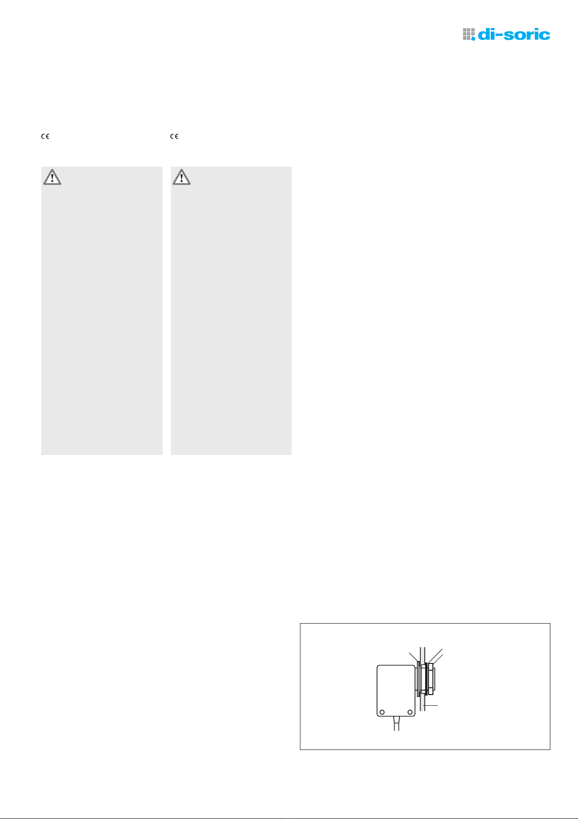
Montage mit Gummiteilen Mounting with rubber parts
Halter mit Bohrung ∅21 /
retaining plate with bore ∅21
Gummibuchse / rubber bush Unterlegscheibe / washer
Mutter / nut
Elektrischer Anschluss
!Der elektrische Anschluss muss EMV-
gerecht ausgeführt werden.
!Für die Spannungsversorgung muss ein
EMV-gerechtes Netzteil verwendet
werden.
!Der Minuspol der Stromversorgung und
der Maschinenkörper müssen geerdet
werden.
!Anschlusskabel und Stromversorgungs-
leitungen nicht in unmittelbarer Nähe
von Leitungen höherer Spannungen
oder mit Leitungen, die induktive oder
kapazitive Lasten schalten, verlegen.
!Die max. Länge der Anschlussleitungen
darf 100 m nicht überschreiten. Der
Leitungsquerschnitt muss entsprechend
ausgelegt sein (Spitzenstrom!).
iDie Stromversorgung muss so dimensio-
niert sein, dass pro Sensor kurzzeitig
(120 µs) ein Spitzenstrom von ca. 0,1 A
(US 46 K 150 ...) bzw. 0,25 A
(US 46 K 500 ...) geliefert werden kann.
iDie Stromversorgungsleitungen zum
Sensor sollten möglichst kurz sein. Bei
langen Stromversorgungsleitungen (ab
20 m) müssen am Sensor Stützkonden-
satoren (z.B. 470 µF / 35 V) parallel zur
Betriebsspannung angeschlossen
werden.
Der elektrische Anschluss erfolgt typab-
hängig über 3-polige Anschlusskabel mit
M8-Steckverbinder oder über fest ange-
schlossene Anschlusskabel.
Wartung und Reparatur
!Keine lösungsmittelhaltigen Reiniger
verwenden.
!Ultraschall-Sensoren nicht mit heißem
Dampf reinigen.
Ultraschall-Sensoren US... sind weitestge-
hend wartungsfrei.
Ablagerungen auf der Schallwandlerober-
fläche regelmäßig mit einem weichen
Tuch entfernen.
Reparatur nur durch di-soric.
Gewährleistung
Es gelten die gesetzlichen Gewährleistungs-
bestimmungen.
Electrical connection
!The electrical connection must be made
in such a manner as to ensure electro-
magnetic compatibility (EMC).
!Please us an EMC-compliant power
pack for the power supply.
!The negative terminal of the power
supply and the machine body must be
connected to ground.
!Do not lay connection lead and power
supply cables in the direct vicinity of
cables conducting high voltages or
cables which switch inductive or capa-
citive loads.
!The connection leads may not exceed a
max. length of 100 m. The cable cross-
section must be designed accordingly
(peak current!).
iThe power supply must be rated such
that a peak current of approximately
0.1 A (US 46 K 150 ...) or 0.25 A
(US 46 K 500 ...) can be supplied per
sensor briefly (120 µs).
iThe power supply leads to the sensor
should be as short as possible. In the
case of long power supply leads (up-
wards of 20 m), connect back-up
capacitors on the sensor (e.g. 470 µF /
35 V) in parallel with the operating
voltage.
Depending on type, the unit must be
connected electrically via a 3-core connec-
tion cable with M8 plug connector or via
permanently connected connection cable.
Maintenance and repair
!Please do not use cleaning agents
containing solvents.
!Do not clean ultrasonic sensors with
hot steam.
Ultrasonic sensors US... are largely mainte-
nance-free.
Regularly remove deposits on the surface
of the sound transducer using a soft cloth.
Repair by di-soric only.
Warranty
The legal warranty regulations apply.
Anschlussschema Connection diagram
BN
BK
BU
1
4
3
S
pnp
Einstellen des Schaltabstandes
!Verwenden Sie zum Einstellen des
Potentiometers unbedingt den mitge-
lieferten Miniaturschraubendreher. Die
Verwendung eines ungeeigneten
Werkzeugs kann zur Beschädigung des
Sensors führen.
Der Schaltabstand des Sensors kann über
Potentiometer 1 innerhalb des Arbeitsbe-
reiches eingestellt werden.
Der Schaltzustand des Ausgangs wird
durch eine rote LED angezeigt.
- Objekt im gewünschten Abstand im
Abtastfeld plazieren.
iDer Minimalabstand muss größer als
der Blindbereich sein (siehe Abtastfel-
der).
- Potentiometer gegen den Uhrzeigersinn
auf Linksanschlag stellen.
- Potentiometer langsam im Uhrzeiger-
sinn drehen, bis der Ausgang schaltet.
Setting the sensing distance
!It is imperative you use the miniature
screwdriver supplied to adjust the
potentiometer. The use of an unsuitab-
le tool can result in damage to the
sensor.
The sensing distance of the sensors can be
set within the operating range using
potentiometer 1.
The switching state of the output is
displayed on a red LED.
- Place object at the required distance in
the detection area.
iThe minimum distance must be greater
than the blind zone (see detection
areas).
- Turn potentiometer counter-clockwise to
the left stop.
- Slowly turn potentiometer clockwise
until the output switches.
Poti 1:
Abstand/distance, LED rot / red
Poti 2:
US 46 K 150 ...: Hysterese/hysteresis
10 ... 40 %
US 46 K 500 ...: Impulsverlängerung/pulse stretching
0,4 ... 8 s
min.
max.
min.
max.
Maßzeichnungen / Dimensional drawings
US 46 K 150 PSLK US 46 K 500 PSLK
mm (typ.)
Abtastfelder
Die abgebildeten Abtastfelder sind Richtwerte. Die Breite der Schallkeule und die Reich-
weite sind abhängig von der Größe und Beschaffenheit des Objektes und dessen geo-
metrischer Lage in Bezug zum Sensor. Ebenso hat die Lufttemperatur und -feuchtigkeit
einen Einfluss auf die Größe des Abtastfeldes. Bei tiefer Temperatur und niedriger
Feuchtigkeit wird das Feld größer.
iIm Blindbereich können keine Objekte erfasst werden.
Detection areas
The detection areas shown are approximate. The width of the sound lobe and the
range are dependent on the size and characteristics of the object and its geometric
position in relation to the sensor. The air temperature and the humidity will also have an
effect on the size of the detection area. The area is larger at lower temperatures and
lower humidity.
iIt is not possible to detect any objects in the blind zone.
US 46 K 150 ... US 46 K 500 ...
Technische Daten Technical data US 46 K 150 ... US 46 K 500 ...
bei 20 °C, 24 V DC at 20 °C, 24 V DC
Arbeitsbereich Scanning range ca. 60 ... 150 mm ca. 120 ... 500 mm
Sendefrequenz Operating frequency 350 kHz 175 kHz
Betriebsspannung Service voltage 12 ... 28 V DC 12 ... 28 V DC
Eigenstromaufnahme Internal power consumption ca. 45 mA ca. 55 mA
Spitzenstrom Peak current ca. 100 mA ca. 250 mA
Schaltausgang Binary output Transistor pnp, 100 mA, NO Transistor pnp, 100 mA, NO
Schaltfequenz Switching frequency ca. 15 Hz ca. 2 Hz
Ansprechzeit Response time < 5 ms < 10 ms
Abfallzeit (Impulsverlängerung) Release time (pulse stretching) < 40 ms 0,4 ... 8 s
einstellbar / adjustable
Schalthysterese axial Switching hysteresis, axial 10 ... 40 % ca.10 %
einstellbar / adjustable
Reproduzierbarkeit Reproducibility < 1 % / Sn max. < 1 % / Sn max.
Temperaturdrift Schaltausgang Temperature drift switching output typ. - 0,1 %/K typ. - 0,1 %/K
Temperaturdrift Luftstrecke Temperature drift air path - 0,17 %/K - 0,17 %/K
Umgebungstemperatur Ambient temperature -20 ... + 50 °C -20 ... + 50 °C
Schutzart Protection class IP 67 IP 67
mm (typ.)
Abstand/distance
LED
Hysterese/hysteresis
US 46 K 150 PSK-TSSL
Abstand/distance
LED
Hysterese/hysteresis
M8x1
Abstand/distance
LED
Impulsverlängerung/
pulse stretching
Abstand/distance
LED
Impulsverlängerung/
pulse stretching
M8x1
US 46 K 500 PSK-TSSL
200
400
0
100
300
500
200
Blindbereich
blind zone
150
0
50
100
50
Blindbereich
blind zone
di-soric
Industrie-electronic GmbH & Co.
Steinbeisstraße 6
D 73660 Urbach
Telefon ++49 (0) 71 81 / 98 79 0
Telefax ++49 (0) 71 81 / 98 79 21
e-mail [email protected]
Internet www.di-soric.de
Alle technischen Angaben beziehen sich auf den
Stand 11/05, Änderungen bleiben vorbehalten.
Da Irrtümer und Druckfehler nicht auszuschließen
sind, gilt für alle Angaben „ohne Gewähr“.
All technical specifications refer to the state of
the art 11/05, they are subject to modifications.
As typographical and other errors cannot be excluded,
all data are given „without engagement“.

Other Di-soric Accessories manuals

Di-soric LHT 9-45 M 10 P3IU-B4 User manual

Di-soric

Di-soric LHT 9-45 M 10 P3IU-B4 User manual

Di-soric OTV Series User manual

Di-soric

Di-soric OTV Series User manual

Di-soric OGUL Series User manual

Di-soric

Di-soric OGUL Series User manual

Di-soric OTV 22 K 160 P2K User manual

Di-soric

Di-soric OTV 22 K 160 P2K User manual

Di-soric KSSTI 400 G3K-TSSL User manual

Di-soric

Di-soric KSSTI 400 G3K-TSSL User manual

Di-soric UGUTI 6/70 G6-RB5 User manual

Di-soric

Di-soric UGUTI 6/70 G6-RB5 User manual

Di-soric FS 12-100-1 M G8-B8-E User manual

Di-soric

Di-soric FS 12-100-1 M G8-B8-E User manual

Di-soric FSB 10 M G1-B8 User manual

Di-soric

Di-soric FSB 10 M G1-B8 User manual

Di-soric USCTI 18 M 700 FPSK-BSL User manual

Di-soric

Di-soric USCTI 18 M 700 FPSK-BSL User manual

Di-soric USGT 60/8 U-B4 User manual

Di-soric

Di-soric USGT 60/8 U-B4 User manual

Di-soric USCRTI 18 M 200 FPSK-BSL User manual

Di-soric

Di-soric USCRTI 18 M 200 FPSK-BSL User manual

Di-soric FS 12-50 M G3-B8 User manual

Di-soric

Di-soric FS 12-50 M G3-B8 User manual

Di-soric PS-30 User manual

Di-soric

Di-soric PS-30 User manual

Di-soric FS 12-100-1 M G8-B8 User manual

Di-soric

Di-soric FS 12-100-1 M G8-B8 User manual

Di-soric OTV 22 K 115 P1K User manual

Di-soric

Di-soric OTV 22 K 115 P1K User manual

Di-soric OGL 051 P3K-TSSL Instruction manual

Di-soric

Di-soric OGL 051 P3K-TSSL Instruction manual

Di-soric OKTTI 55 M 30 FG3LK-IBS User manual

Di-soric

Di-soric OKTTI 55 M 30 FG3LK-IBS User manual

Di-soric LAT52-500IU-B5 User manual

Di-soric

Di-soric LAT52-500IU-B5 User manual

Di-soric FS 12-100-1 M G8-B8-PB User manual

Di-soric

Di-soric FS 12-100-1 M G8-B8-PB User manual

Di-soric OTV 22 K 14 P1K User manual

Di-soric

Di-soric OTV 22 K 14 P1K User manual

Di-soric LAT 51 M 500 UG3-B5 User manual

Di-soric

Di-soric LAT 51 M 500 UG3-B5 User manual

Di-soric LVHT52-500G3-B4 User manual

Di-soric

Di-soric LVHT52-500G3-B4 User manual

Di-soric UGUTI 6/70 G6-B5 User manual

Di-soric

Di-soric UGUTI 6/70 G6-B5 User manual

Di-soric LHT 9-45 M 10 P3-B4 User manual

Di-soric

Di-soric LHT 9-45 M 10 P3-B4 User manual

Popular Accessories manuals by other brands

Takuma e-Foil user guide

Takuma

Takuma e-Foil user guide

Resol CS-I manual

Resol

Resol CS-I manual

PCB Piezotronics M101A05 Installation and operating manual

PCB Piezotronics

PCB Piezotronics M101A05 Installation and operating manual

ARC'TERYX VOLTAIR 21827 user manual

ARC'TERYX

ARC'TERYX VOLTAIR 21827 user manual

Carrier 09LF Series manual

Carrier

Carrier 09LF Series manual

CTI GG-CO2 Installation and operation manual

CTI

CTI GG-CO2 Installation and operation manual

Optex OAM-DUAL TE quick guide

Optex

Optex OAM-DUAL TE quick guide

Pepperl+Fuchs UC2000-L2-E4-V15 manual

Pepperl+Fuchs

Pepperl+Fuchs UC2000-L2-E4-V15 manual

Dometic 8953001.400 Series installation instructions

Dometic

Dometic 8953001.400 Series installation instructions

Panasonic HL-C2 Series user manual

Panasonic

Panasonic HL-C2 Series user manual

LEGRAND adorne WNAR153 installation instructions

LEGRAND

LEGRAND adorne WNAR153 installation instructions

Autonics BD Series product manual

Autonics

Autonics BD Series product manual

NHR ZigBee S05-ST user manual

NHR

NHR ZigBee S05-ST user manual

GE 19298 user manual

GE

GE 19298 user manual

PCB Piezotronics 108A02 Installation and operating manual

PCB Piezotronics

PCB Piezotronics 108A02 Installation and operating manual

veoneer 77V125CRN user manual

veoneer

veoneer 77V125CRN user manual

Alecto ADB-11 Installation

Alecto

Alecto ADB-11 Installation

Agan Aroma Moodo manual

Agan Aroma

Agan Aroma Moodo manual

manuals.online logo
manuals.online logoBrands
  • About & Mission
  • Contact us
  • Privacy Policy
  • Terms and Conditions

Copyright 2025 Manuals.Online. All Rights Reserved.