SSRLS-3 / SSRLU-3
OUT SWING MODEL
Installation Instructions
INS SSRLS_SSRLU-3 v10.2.vsd Created: 5-14-2018 Revised: 5-14-2018 Page 2
44"
(suggested)
Select a height
which is
comfortable
for users
Select a height
which is
comfortable
for users
44"
(suggested)
Select a height
which is
comfortable
for users
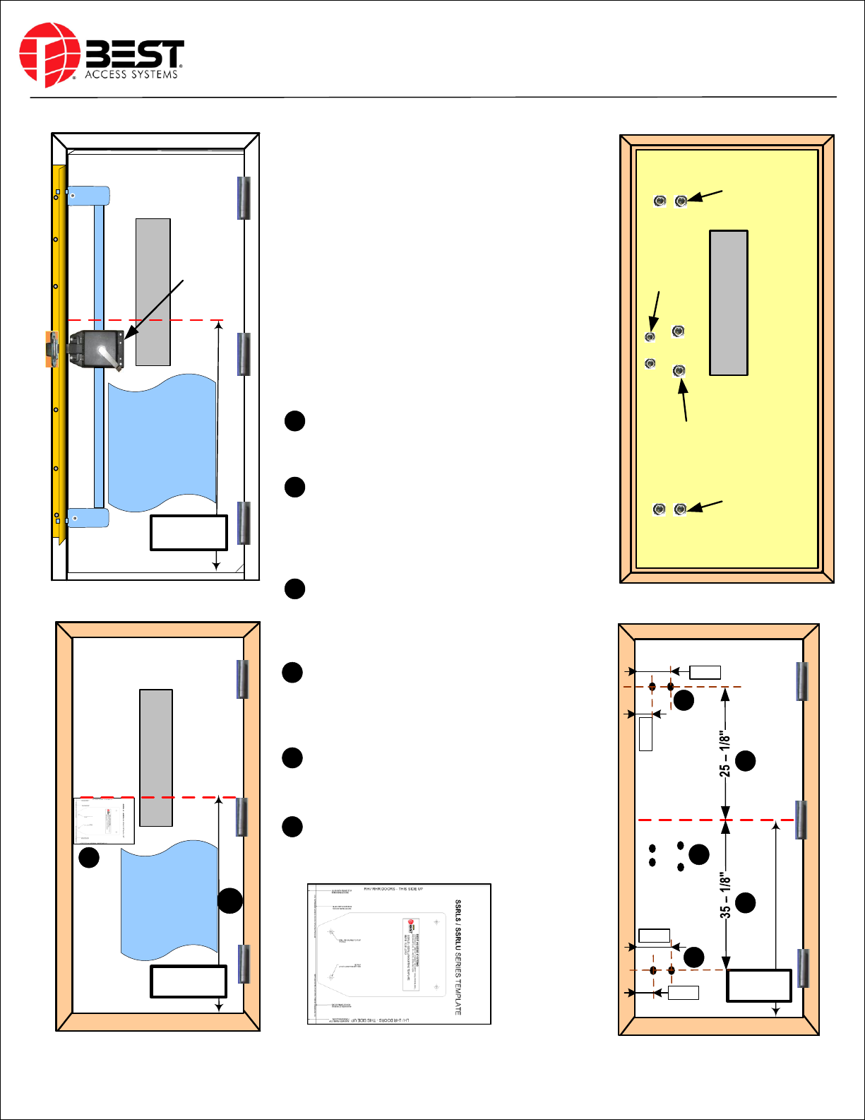
OUT-SWING MODEL
Upper Module
Lower
Module
Channel
Main Lock
Body
Bolt
Extended
Aluminium Angle
44"
(suggested)
Select a height
which is
comfortable
for users
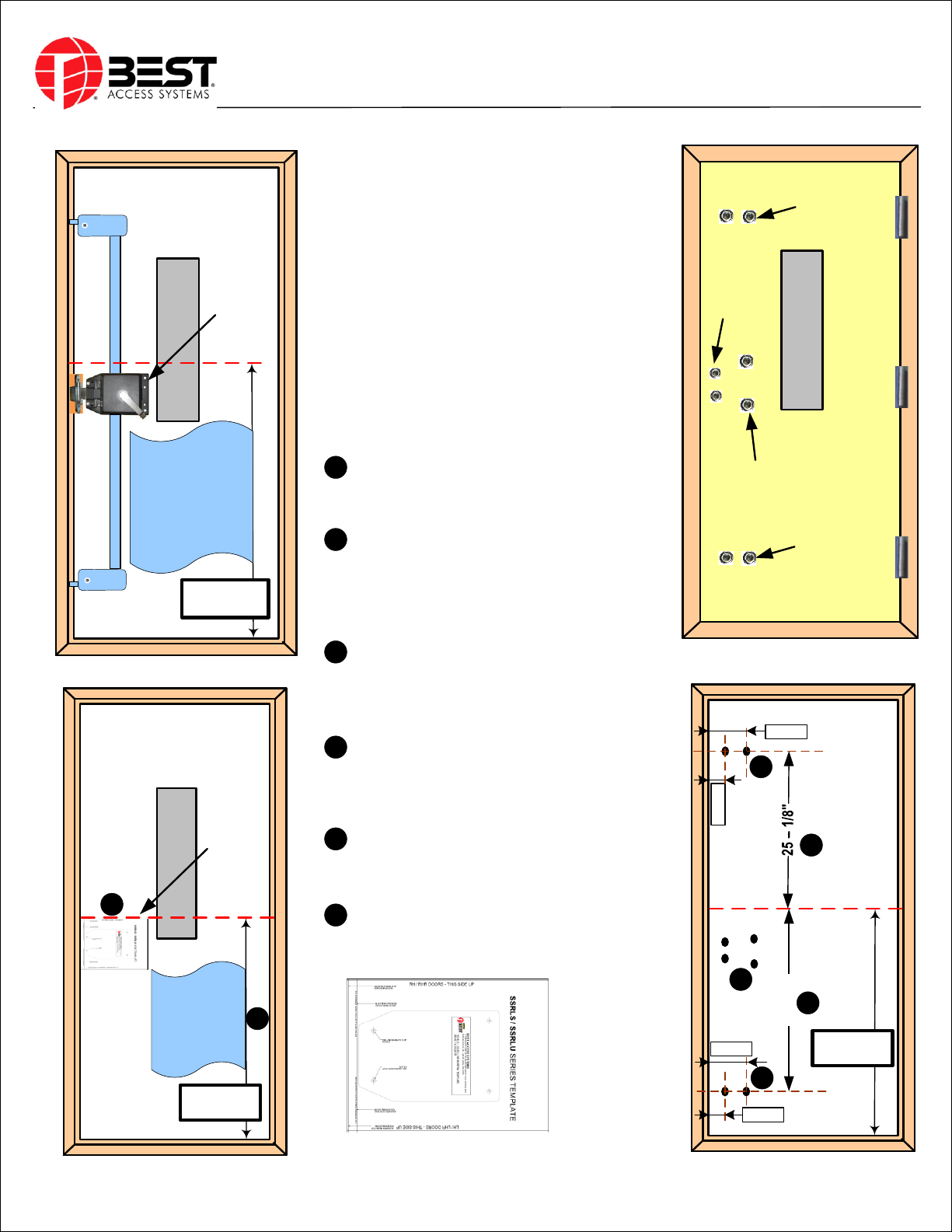
OUT-SWING MODEL
Upper Module
Lower
Module
Channel
Main Lock
Body
Bolt
Extended
Aluminium Angle
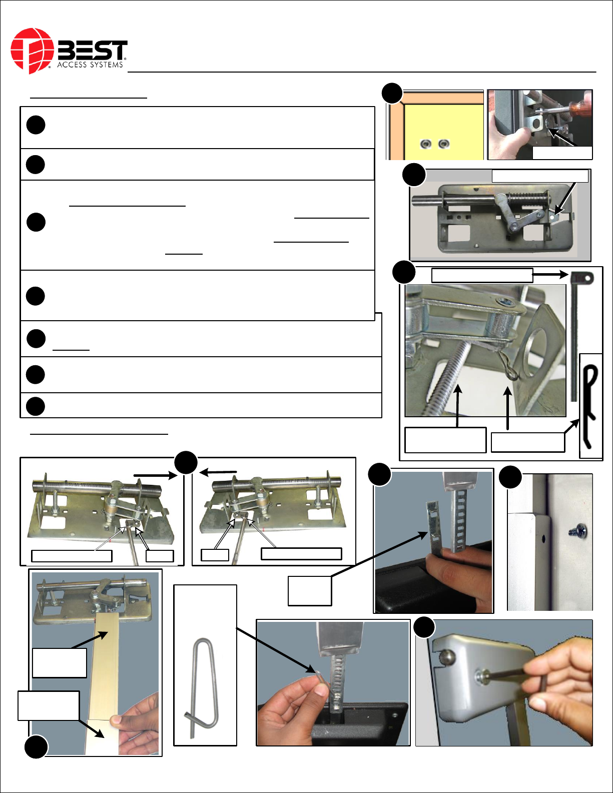
The locksets are handed. When unlocked, the lever should
always point upward at a 45° angle.
3- Point Horizontal Lock Installation
DOOR MARKING & DRILLING:
IMPORTANT: Make sure the door swings free and smooth before
you begin the installation. Remove all old locks, exit devices, any
slide bolts or other hardware & brackets. Make sure any exposed
holes left from previous hardware are completely covered after
installation.
Make any adjustments to make the door swing FREELY before
you start marking and installing.
1) Mark a horizontal reference line on the corridor side of the
door, at a height of 44" from the bottom of the door (not
floor). Extend the line to the hinge side of the door.
2) Line up the template with the horizontal reference line and
the door edge then tape it to the door. Please refer the
cardboard template to mark and drill the holes. Drill (4) 3/8"
through holes (TIP: Start with 1/8"). Make sure you drill
level.
3) Select a location for the height of the top module
(suggested at a height of 25-1/8" from the horizontal
reference line). Mark a horizontal line approx. 12" from the
lock edge of the door. Make sure the line is level.
4) Select a location for the height of the bottom module
(suggested at a height of 35-1/8" from the horizontal
reference line). Mark a horizontal line approx. 12" from the
lock edge of the door. Make sure the line is level.
5) Draw two vertical lines, one at a distance of 1-½” and
another at a distance of 4-½” from door edge on the top and
bottom horizontal module lines.
6) Punch the center point at vertical and horizontal lines
intersect as shown. Drill pilot holes first. Drill (2) top holes
and (2) bottom holes of 3/8" dia. through the door.
A
CORRIDOR SIDE OF THE DOOR
Stamped Washer
Stamped Washer &
Carriage Bolt Assly.
B
ROOM SIDE OF THE DOOR
44"
(suggested)
Cardboard
Template
OUT-SWING MODEL
Reference Line
A
44"
(suggested)
OUT-SWING MODEL
Reference Line
C
D
EC
D
E
E
1-½”
Stamped Washer
1-½”
4-½”
4-½”
E
SSRLS / SSRLU
Cardboard Template
CORRIDOR SIDE OF THE DOOR ROOM SIDE OF THE DOOR
B
Cardboard
Template
B
Select a height
which is
comfortable
for users
Carriage
Bolt &
Washer
Assly.