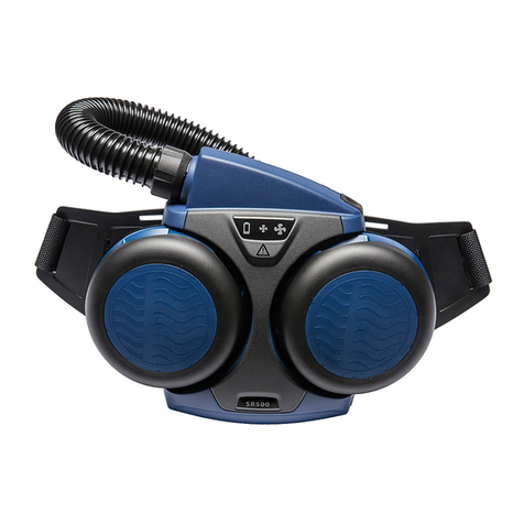
saver PP Series with second medium-pressure connector
Positive-pressure escape equipment Instructions for Use
Dow Corning®and Molykote®are registered trademarks of Dow Corning Corporation. 3359829 (A3-D-P) Page 2 of 2
3359829
© Dräger Safety UK Limited
Edition 07 – December 2018 (Edition 01 – May 2011)
Subject to alteration
Draeger Safety UK Limited
Ullswater Close Tel +44 1670 352 891
Blyth, NE24 4RG Fax +44 1670 356 266
United Kingdom www.draeger.com
WARNING
The air supply pressure to the second medium-pressure connector
must not exceed 10 bar. Do not connect high-pressure air. Using
an air supply that does not comply with the air quality, pressure
and flow requirements could result in death or serious injury for the
user.
If the second medium-pressure connector is used in a potentially
contaminated environment, ensure that all couplings are free of
contaminants before connecting.
Alternative medium-pressure breathing-air source:
Pressure and flow: 6 to 10 bar at an air flow rate of at least 550 litres/
minute.
1. Remove the second medium-pressure connector (Fig 3, Item 1) from the
carrying bag and ensure that the breathing-air outlet connector is
compatible with the connector on the saver PP.
2. Remove the protection caps, ensure that the hoses are not bent or
kinked, and push the connectors together until a click is heard.
○The air supply to the wearer from the alternative medium-pressure
breathing-air source begins immediately. Depending on the alternative
source supply pressure, the remaining air in the saver PP air cylinder
may be used.
WARNING
Once the wearer has connected to an alternative medium-pressure
breathing-air source, further use of the saver PP for escape is not
possible. Do not disconnect the alternative medium-pressure
breathing-air source until the air in the muster area becomes safe to
breathe or another breathing device is available.
3. When possible, disconnect the alternative medium-pressure breathing-air
source and remove the saver PP as detailed in Section 3.3.1.
3.4 After use
After any use, the product must be checked and then returned to the ready-
for-use condition. The after use maintenance tasks (see Section 4.1.2)
must be carried out by trained service personnel or Dräger to prepare the
product for use.
4 Preparing and maintaining the saver PP
The tasks in this section must be carried out to prepare and maintain the
saver PP in a ready-for-use condition.
4.1 Maintenance periods
4.1.1 Daily checks
It is essential that escape apparatus is ready for use at all times, and
Dräger therefore recommend a daily check. If the customer’s on-site risk
assessment concludes that less regular checks are acceptable, this can be
extended to a maximum of one month. It is the customer’s responsibility to
ensure that the equipment is ready for use at all times.
●Check that the pointer of the cylinder pressure gauge is inside the
green area. Charge the cylinder if it is in the red area (see Section
4.2.5).
●Check the anti-tamper tag(s) on the lid of the bag (Fig 4). If a tag is
broken, inform trained service personnel or Dräger immediately.
4.1.2 Maintenance table
Service and test the breathing apparatus, including out-of-use apparatus,
in accordance with the maintenance table. Record all service details and
testing. Refer also to the Instructions for Use for the lung demand valve,
face mask and other associated equipment.
Additional inspection and testing may be required in the country of use to
ensure compliance with national regulations.
Notes
Dräger recommendations
1. Clean the equipment if it is dirty. If it the equipment has been exposed
to contaminants, disinfect any components that come into direct and
prolonged contact with the skin.
2. These maintenance tasks may only be carried out by Dräger or trained
service personnel. Details of the tasks are contained in the technical
manual which is issued to service personnel that have attended a
relevant Dräger maintenance course.
3. As a guide, lubricant should be felt on the fingers but not seen. If
relubrication is required, lightly apply Dow Corning®Molykote®111
(other lubricants are not tested and may damage the equipment).
Component
/System
Task After
use
Every
year
Every
10
years
Complete
equipment
Visual inspection (see Note 1
and Section 4.2.1)
Leak test (see Section 4.2.6)
Functional tests (see Note 2)
Lung
demand
valve O-ring
Check and lubricate if necessary
(see Note 3)
Pressure
reducer
Basic overhaul. Contact Dräger
for the Repair Exchange Service
(REX)
Cylinder
valve
Basic overhaul. Contact Dräger
for the Repair Exchange Service
(REX)
Cylinder Charge to correct pressure (see
Section 4.2.5)
Cylinder pressure test and
recertification; check the test
date on the cylinder
Carry out in line with
national regulations
!
4.2 Maintenance tasks
4.2.1 Visual inspection
Carry out a visual inspection, checking the full breathing apparatus
including all component parts and accessories. Check that the equipment
is clean and undamaged, paying particular attention to pneumatic
components, hoses and connectors. Typical signs of damage that may
affect the operation of the breathing apparatus include impact, abrasion,
cutting, corrosion and discoloration. Report dirty or damaged equipment to
trained service personnel or Dräger, and do not use until faults are rectified
and the product is cleaned.
4.2.2 Fitting the cylinder
1. Ensure that the pointer of the cylinder pressure gauge is inside the
green area (fully charged to 200 bar).
2. Check that the threads of the valve port and the pressure reducer hand
wheel are undamaged, and the O-ring (Fig 8, Item 1) is in position and
undamaged.
3. Align the pressure reducer as shown in Fig 9 then screw it into the
cylinder valve hand tight. Ensure that the pressure reducer is fully
screwed into the cylinder valve (screw threads must not be visible).
4. Carry out the leak test (see Section 4.2.6).
5. Press the reset button (Fig 2, Item 1) to ensure that the lung demand
valve is switched off.
6. Pull the elasticated head harness of the face mask over the front of the
mask (Fig 10).
NOTICE
Note that the mask visor faces upward in a soft-case carrying bag and
faces downward in a hard-case carrying bag.
Route rubber hoses in such a way that the bend radius is not too
acute and the hose is not stretched, compressed or twisted.
7. Fit the cylinder and mask as follows:
○Soft-case carrying bag:
i. Fully insert the cylinder into the carrying bag.
ii. Fit the pressure gauge shroud into the cut-out section in the
side of the bag.
iii. Connect the hook-and-loop strap around the cylinder.
iv. Fit the face mask into the carrying bag, ensuring that the
harness lugs (Fig 11, Item 1) of the mask are flat and wrapped
around the cylinder as shown.
○Hard-case carrying bag:
i. Place the cylinder on the fully open case (Fig 12) and fit the
neck strap as shown.
ii. Close the carrying bag body, ensuring that the pressure gauge
shroud remains in its holder.
iii. Fit the securing screws (Fig 13) (5 mm hexagon key and a
10 mm socket required). Dräger recommend a torque of 2 Nm
(1.5 lbf ft). The nylon in the locknut must exhibit an
interference with screw threads – if interference is not felt,
replace with a new M6 self-locking nut.
iv. Refit the lid into the slot on the bag.
v. Fit the face mask into the carrying bag (Fig 14).
8. Seal the lid along the hook-and-loop strip leaving sufficient opening to
insert a hand and, taking care not to detach the locking clip from the
cylinder valve, connect the sprung-gate clip (Fig 1, Item 2) to the D-
ring (Fig 1, Item 1).
9. Fit the anti-tamper tag(s) and close the lid (Fig 4).
4.2.3 Removing the cylinder
WARNING
High-pressure air release may cause injury to the user or other
personnel near the breathing apparatus. Ensure that the locking
clip is fitted in the cylinder valve and fully vent the system before
attempting to disconnect the air cylinder.
When the cylinder valve outlet is open to atmosphere (not
connected to the pressure reducer or a charging adaptor), do not
remove the locking clip unless the cylinder is completely
discharged. Removing the locking clip would immediately exhaust
high-pressure cylinder air. To fully discharge the cylinder, see
Section 4.2.4.
1. If the carrying bag is closed, break the anti-tamper tag(s) and carefully
open the lid, ensuring that the locking clip (Fig 1, Item 3) remains fitted
in the cylinder valve.
2. Disconnect the sprung-gate clip (Fig 1, Item 2) from the D-ring (Fig 1,
Item 1) and then fully open the lid.
3. Remove the face mask from the bag.
4. Press the front button (Fig 2, Item 2) to fully vent the system.
5. Remove the cylinder as follows:
○Soft-case carrying bag: release the hook-and-loop strap and
carefully remove the cylinder.
○Hard-case carrying bag: remove the screws from the carrying bag
body (Fig 13) (5 mm hexagon key and a 10 mm socket required),
fully open the carrying bag body and then carefully remove the
cylinder. Remove the lid from the slot on the bag.
6. Unscrew the pressure reducer from the cylinder valve.
4.2.4 Fully discharging the air cylinder
1. Ensure that the pressure reducer is connected to the cylinder valve.
2. Remove the locking clip from the cylinder valve (Fig 15).
3. Press the front button (Fig 2, Item 2) of the lung demand valve and
allow the cylinder to fully vent. Do not direct the air toward the face,
eyes or skin.
4.2.5 Air cylinder charging
WARNING
Air quality for compressed-air cylinders shall meet the
requirements for breathing air according to EN12021.
●The charging connector is a G5/8 connector as per EN 144-2.
●Refer also to the instructions supplied with the cylinder and the
charging unit for recharging the cylinder.
●Only charge compressed-air cylinders which:
○Conform to national standards.
○Feature the original manufacturer’s test date and test mark.
○Have not exceeded the test date indicated on the cylinder by the
last testing station.
○Are not damaged.
●Dräger recommend a charge rate of 27 bar/minute (rapid charging will
increase the temperature resulting in an incomplete charge).
!
!
●To prevent overcharging of the cylinder, Dräger recommend using a
pressure-limiting device on the charging compressor.
1. Remove the cylinder (see Section 4.2.3).
2. Connect the charging adaptor to the cylinder valve (Fig 16).
3. If the cylinder is still pressurized, approximately match the charging
line pressure to the cylinder pressure.
4. Remove the locking clip from the cylinder valve (Fig 15).
5. Recharge to the rated working pressure of the cylinder (200 bar).
○Compression of cylinder air can cause a small temperature
increase during refilling, resulting in an incomplete charge. If
necessary, top-up the cylinder when it cools.
6. When the cylinder is fully charged, refit the locking clip. Press the
button down against the spring and insert the locking clip into the slot
(Fig 17), ensuring that the button remains in the locked (down)
position.
7. Vent pressure from the charging hose and then remove the charging
adaptor from the valve.
8. Refit the cylinder (see Section 4.2.2).
4.2.6 Leak test
WARNING
If breathing apparatus fails to meet any of the standards or
parameters described in the leak test, or if an immediate leak is
evident, there is a system fault. Report the fault to trained service
personnel or contact Dräger. Do not use the breathing apparatus
until the fault condition is rectified.
1. Ensure that the pointer of the cylinder pressure gauge is inside the
green area.
2. Press the reset button (Fig 2, Item 1) to ensure that the lung demand
valve is switched off.
3. Remove the locking clip from the cylinder valve to pressurize the
system and then refit the locking clip. Press the button down against
the spring and insert the locking clip into the slot (Fig 17), ensuring that
the button remains in the locked (down) position.
○There should be no audible leak. If there is any leak, investigate
and repair the leak before use. If necessary, use a soapy solution
to locate the leak.
4. Press the front button (Fig 2, Item 2). A small amount of air will vent
from the system.
5. Press the reset button (Fig 2, Item 1) to switch off the air flow through
the lung demand valve.
4.3 Cleaning and disinfecting
CAUTION
Do not exceed 60 °C for drying, and remove components from the
drying facility immediately when dry. Drying time in a heated dryer
must not exceed 30 minutes.
Do not immerse pneumatic or electronic components in cleaning
solutions or water.
If water is trapped and then freezes inside the pneumatic system
of the breathing apparatus (such as the lung demand valve),
operation will be impaired. Prevent any liquid from entering, and
thoroughly dry the breathing apparatus after cleaning to prevent
this from occurring.
For information about suitable cleaning and disinfecting agents
and their specifications refer to document 9100081 on
www.draeger.com/IFU.
Refer also to the Instructions for Use for the lung demand valve, face mask
and other associated equipment.
●Use only clean lint-free cloths
1. Clean the breathing apparatus manually using a cloth moistened with
cleaning solution to remove excess dirt.
2. Apply disinfecting solution to all internal and external surfaces.
3. Rinse all components thoroughly with clean water to remove all
cleaning and disinfecting agents.
4. Dry all components using a dry cloth, in a heated dryer or in air.
5. Contact service personnel or Dräger if disassembly of pneumatic or
electronic components is required.
5 Troubleshooting
There is no user troubleshooting on the saver PP. Contact trained service
personnel or Dräger to report any issues with the product.
6 Storage
Store the equipment between -15 °C and +25 °C. Ensure that the
environment is dry, free from dust and dirt, and does not subject the
equipment to wear or damage due to abrasion. Do not store the equipment
in direct sunlight. Note also the following:
●Extend the neck strap and, if fitted, the waist belt. On the hard-case
carrying bag, the neck strap can be fed into the bag at the front and
rear slots to tidy the strap.
●Fix the apparatus securely to any raised mounting point to prevent it
from falling.
●Contact Dräger for suitable storage cabinets and wall mounting kits.
7 Disposal
When required, dispose of the saver PP in accordance with national or local
regulations for waste disposal.
Order list
Description Quantity Order code
Anti-tamper tags 5 3350388
Waist belt 1 3350396
Dow Corning®Molykote®111 100 grams 3331247
Self-locking nut (M6 with nylon insert) 50 1333062


