manuals.online logo
Brands
  1. Home
  2. •
  3. Brands
  4. •
  5. Draper
  6. •
  7. Projection Screen
  8. •
  9. Draper Onyx User manual

Draper Onyx User manual

Other manuals for Onyx

2

Other Draper Projection Screen manuals

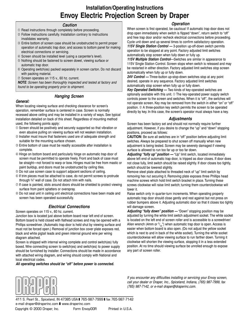
Draper Lace & Grommet Installation instructions

Draper

Draper Lace & Grommet Installation instructions

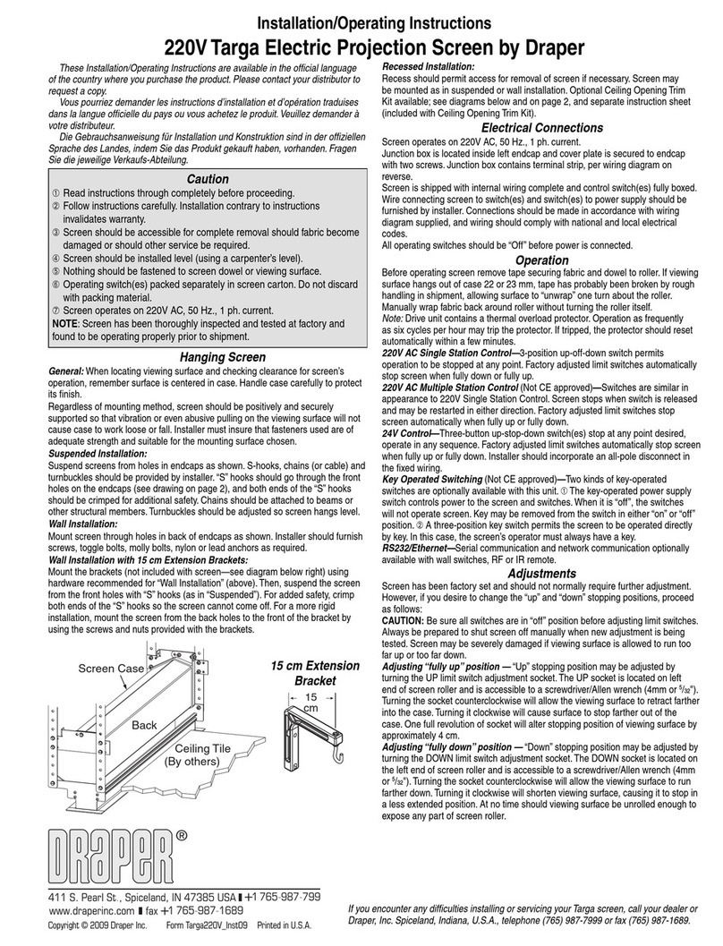
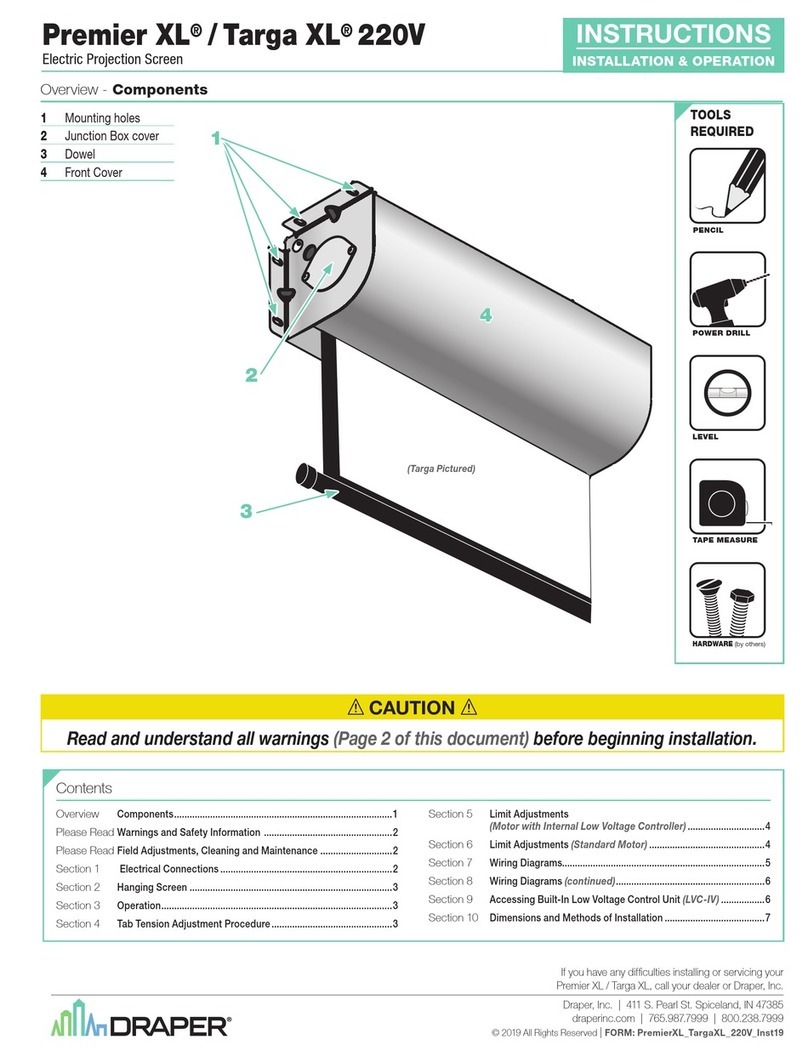
Draper Targa 220V Manual

Draper

Draper Targa 220V Manual

Draper FocalPoint User manual

Draper

Draper FocalPoint User manual

Draper Signature Series E User manual

Draper

Draper Signature Series E User manual

Draper M Series Manual

Draper

Draper M Series Manual

Draper Odin User manual

Draper

Draper Odin User manual

Draper Portable Projection Screen User manual

Draper

Draper Portable Projection Screen User manual

Draper Signature/Series V Manual

Draper

Draper Signature/Series V Manual

Draper Access FIT Series Installation instructions

Draper

Draper Access FIT Series Installation instructions

Draper Clarion User manual

Draper

Draper Clarion User manual

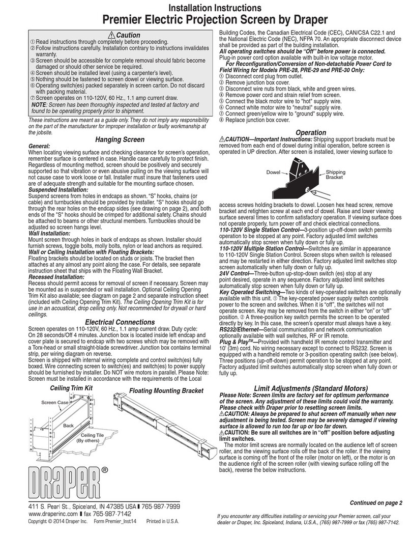
Draper Premier 220V Installation instructions

Draper

Draper Premier 220V Installation instructions

Draper Luma 2 Guide

Draper

Draper Luma 2 Guide

Draper Traveller User manual

Draper

Draper Traveller User manual

Draper Premier PRE-28 User manual

Draper

Draper Premier PRE-28 User manual

Draper Acumen M XT1000E User manual

Draper

Draper Acumen M XT1000E User manual

Draper 220V Access Electric Projection Screen User manual

Draper

Draper 220V Access Electric Projection Screen User manual

Draper Loke User manual

Draper

Draper Loke User manual

Draper Ropewalker Programming manual

Draper

Draper Ropewalker Programming manual

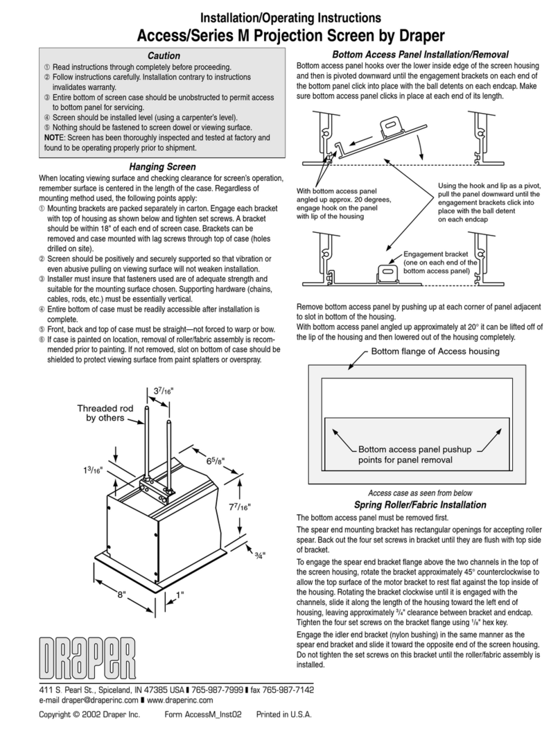
Draper Access/Series M Manual

Draper

Draper Access/Series M Manual

Draper Curved Onyx User manual

Draper

Draper Curved Onyx User manual

Draper Access XL E User manual

Draper

Draper Access XL E User manual

Draper Paragon Series Manual

Draper

Draper Paragon Series Manual

Draper 220V Signature/Series E Manual

Draper

Draper 220V Signature/Series E Manual

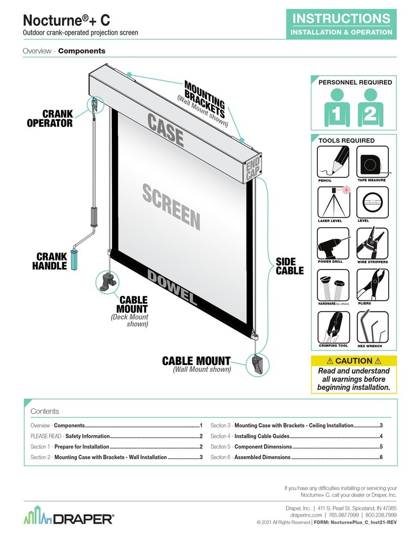
Draper nocturne+ c Installation instructions

Draper

Draper nocturne+ c Installation instructions

Popular Projection Screen manuals by other brands

Elite Screens Elite Tripod Series user guide

Elite Screens

Elite Screens Elite Tripod Series user guide

Laarhoven Companion II General assembly instructions

Laarhoven

Laarhoven Companion II General assembly instructions

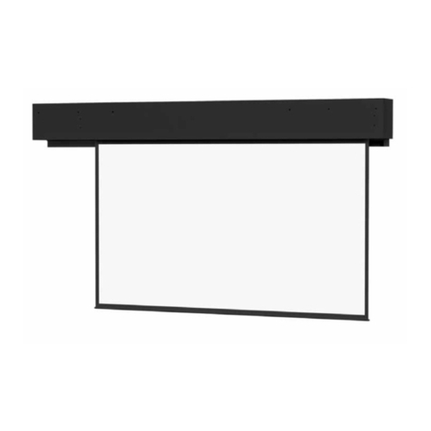
Da-Lite ExecutiveElectrol Instruction book

Da-Lite

Da-Lite ExecutiveElectrol Instruction book

FONESTAR PPTR-43100-FA quick start guide

FONESTAR

FONESTAR PPTR-43100-FA quick start guide

Slide Clear Varro XL installation instructions

Slide Clear

Slide Clear Varro XL installation instructions

OS РХ-090Н user manual

OS

OS РХ-090Н user manual

Niko 10-845 Product information

Niko

Niko 10-845 Product information

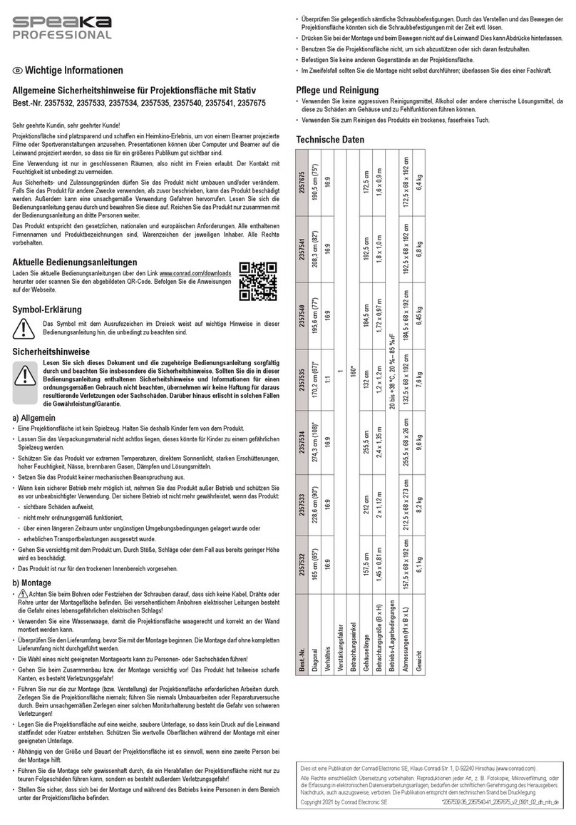
Speaka Professional 2357532 Important information

Speaka Professional

Speaka Professional 2357532 Important information

Sima XL-72 instruction manual

Sima

Sima XL-72 instruction manual

Jasic EVO 2.0 ET-200P Fitting instructions

Jasic

Jasic EVO 2.0 ET-200P Fitting instructions

Renogy RMS-LFPS-US manual

Renogy

Renogy RMS-LFPS-US manual

Elite Screens Starling 2 Series user guide

Elite Screens

Elite Screens Starling 2 Series user guide

InFocus SC-WALL GRY-92H Instruction guide

InFocus

InFocus SC-WALL GRY-92H Instruction guide

Samsung S*H65* user manual

Samsung

Samsung S*H65* user manual

Celexon UST operating instructions

Celexon

Celexon UST operating instructions

JONSBO D31 user guide

JONSBO

JONSBO D31 user guide

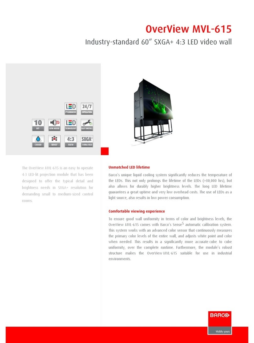
Barco OverView MVL­-615 Brochure & specs

Barco

Barco OverView MVL­-615 Brochure & specs

FONESTAR PPEL-43100-FA quick start guide

FONESTAR

FONESTAR PPEL-43100-FA quick start guide

manuals.online logo
manuals.online logoBrands
  • About & Mission
  • Contact us
  • Privacy Policy
  • Terms and Conditions

Copyright 2025 Manuals.Online. All Rights Reserved.

Assembly/Mounting Instructions
Onyx Permanently Tensioned Projection Screen by Draper
Caution
1Read instructions through completely before proceeding.
2Follow instructions carefully. Installation contrary to instructions
invalidates warranty.
3Screen should be accessible for complete removal should fabric
become damaged or should other service be required.
4Screen should be installed level (using a carpenter’s level).
5Nothing should be fastened to screen frame or viewing surface.
6Make sure you have received all parts (see parts list below and
exploded diagram on page 2).
7Tools Required:
1
/
8
" Allen wrench (included); #2 Phillips screwdriver.
Optional tools: Flat blade screwdriver or small putty knife.
8Installer is responsible for providing appropriate hardware for mounting.
9When lifting assembled screen, do not lift at only one corner; lift at
both corners. Lifting by one corner could result in damage to the
screen frame, especially on large screens.
The ideal temperature range for assembling folding screens to prevent
damaging the surface is 68°-78° F (20°-26° C). Assembling below
recommended temperatures may damage surface and void warranty.
NOTE: Screen has been thoroughly inspected and tested at factory and
found to be operating properly prior to shipment.
Copyright © 2013 Draper Inc. Form Onyx_Inst13 Printed in U.S.A.
®
If you encounter any difficulties installing or servicing your Onyx screen, call your
dealer or Draper, Inc., Spiceland, Indiana, (765) 987-7999 or fax (765) 987-7142.
Onyx—Hardware and Parts List
Frame Preparation
1Clean area and place frame assembly pieces face down. Insert frame
extrusion connectors into aluminum frame extrusions as indicated in
Figures 1 through 4. For easier assembly insert the inner connectors first.
Figure 1
2Make sure frame extrusion connectors are fully seated (see Fig. 5).
Figure 3
Frame Extrusions - 4 Frame Extrusion
Connectors - 8
Wall-Brackets - 2 Viewing Surface - 1
Plastic Tubing - 4
Surface Retention
Extrusions - 4
Front
Back
1
/
8
" Allen Wrench - 1
Figure 4
Figure 7
Figure 5
(Continued on Page 2)
Patented by Draper, Inc., U.S. Patent Nos. 6,785,047; 7,113,332; and 7,369,310.
Caution: When lifting assembled screen, do not lift at only one corner; lift
at both corners. Lifting by one corner could result in damage to the screen
frame, especially on large screens.
Figure 2
3Secure connectors by tightening setscrews (see Fig. 6).
Figure 6
4Repeat steps 1-3 for the remaining corners (see Fig. 7).
The Onyx has a precision cut mitered corner.
Please Note: If corner gaps exist (painted frame only) readjusting the frame
and/or applying a small bead of black silicone to fill the gap is the best solu-
tion. Apply a very small bead of black silicone to area where frame gap exists.
Work silicone into gap (using your finger or a cloth). Remove ALL silicone on
face of frame; only silicone inside gap should remain.
Please Note: If extrusion connectors do not slide into frame extrusions, make
sure that setscrews are backed out enough to allow proper clearance.
Onyx by Draper Page 2 of 2
Figure 10
Mounting Screen to Wall
1Determine height at which screen is to be mounted.
Please Note: Top edge of screen frame will be located 1" above mounting
bracket hole centerline when mounted to wall.
2Mark hole centerline so that both wall brackets can be mounted parallel
and at equal height.
3Install wall brackets so that the outermost edges are safely within overall
length of the aluminum frame extrusion to allow for minor horizontal screen
adjustments. Installer is responsible for providing attachment hardware.
4Position screen slightly above Z-brackets on wall (see Fig. 11).
Surface to Frame Assembly
1Return frame onto clean surface, face down, and drape completed surface
assembly over completed frame profile with rounded edge of surface
retention extrusion visible.
2Insert any side of surface to notch #1 on corresponding side of frame
extrusion (see Fig. 10).
3Insert opposite side of surface to notch #1 of frame extrusion.
4Repeat steps 2-3 with remaining edges of surface.
5Ensure surface retention extrusions are centered lengthwise in tension
slots on all 4 edges of surface.
6If additional tension is desired or required over time, adjust surface one
edge at a time to tension notch #2.
Please Note: It is not necessary to adjust more than one edge at a time to
increase surface tension.
Figure 11
5Lower screen until it engages over wall brackets. Center screen horizontally
on brackets as necessary.
Please Note: Make sure screen is installed level.
Figure 8
Surface Preparation
1Move frame assembly out of the way, unroll viewing surface and place on
smooth/clean surface. Orient viewing surface so that folded side of hem is
visible.
2Insert plastic tubing inside pocket formed by hem on all 4 edges of viewing
surface (see Fig. 8).
3Carefully slide surface retention extrusion (rounded edge visible) along
hem and onto surface on all 4 edges of fabric (see Fig. 9). Caution: Do
not allow fabric to snag on end of extrusion. If the screen
fabric is not parallel with the surface retention extrusion, then
it may slit and tear during installation.
Please Note: To make this step easier, pinch the end of the pocket closed
before sliding it into the surface retention extrusion.
Figure 9
4Surface retention extrusion should extend beyond edge of viewing surface
equally at both ends.
5Verify that all surface retention extrusions are installed with rounded edge
visible and are centered on surface material.
Plastic Tubing
Surface Retention
Extrusion
Back of
Viewing Surface
Back of
Viewing Surface
Onyx (Exploded Rear View)Onyx Frame
—Side Detail*
*Viewing surface is approximately ¼" from wall.
www
.draperinc.com (765) 987-799
9
Wall brackets
supplied with
screen. Installer is
responsible for
ensuring appropriate
screws/bolts are used.
Wall
Surface
Retention
Extrusion
Fabric Attachment Extrusions
Viewing
Surface
1½"
4"
Corner Reinforcement Kit
A Corner Reinforcement kit is required for flown screens. Corner gussets
may only be installed after screen is otherwise completely assembled
(including surface).
1Install frame per Onyx instructions.
2Align corner gusset plate to frame.
3Install the supplied #10-24 x .250" fastener (A) into tapped hole in corner
bracket.
4 Align corner gusset plate parallel with the outer edges of the frame.
5 Drill one hole through frame (using holes in gusset plate as a guide) with
1
/
8
" or #30 drill bit.
6 Install one of the #8 x .750" self-threading fasteners (B) into the hole, and
tighten completely to set the plate in position.
7 Drill the remaining three holes using the gusset plate as a guide.
8 Install the remaining three #8 x .750" self-threading fasteners (B) and
tighten completely to set the plate in position.
Repeat the above steps on the remaining three corners of the screen.
Figure 12
A
B
B
B
B