DSC LE4020 User manual

LE4020/LE4020CF v5.0
LTE Cellular Alarm Communicator
INSTALLATION MANUAL
Warning: This manual contains information on limitations regarding product use and function and information on the limitations as to liability of
the manufacturer. The entire manual should be carefully read.

2
Contents
Section 1: Introduction 4
1.1 Features 4
1.1.1 Technical Specifications 4
1.2 Identification of Parts Model LE4020 7
1.3 Identification of Parts Model LE4020CF 8
Section 2: Installing the LE4020/LE4020CF 9
2.1 C24 Communications Enrollment 9
Section 3: Connecting the LE4020/LE4020CF 12
Section 4: Status LEDs 13
4.1 Operating Modes 13
4.1.1 Normal Mode 13
4.1.2 Service Mode 14
Section 5: Operating Principles 15
5.1 Simulated Landline Mode 15
5.2 Panel Transmission Monitoring (PTM) 15
5.3 Cellular Communications Sequence 15
5.4 Inputs 16
5.5 Outputs 16
5.5.1 Activating the Outputs 16
5.6 Reporting Codes 17
5.7 Swinger Shutdown 18
5.8 Hardware Default 18
5.9 Communicator Reset/Update 18
5.10 Low Power Radio Shutdown 19
5.11 SMS Command and Control 19
5.11.1 Arming/Disarming the Security Panel 19
5.11.2 Remote Control of PGM 20
5.12 Phone Number Call Direction 21
5.13 C24 Communications Remote Programming 21
Section 6: Troubleshooting Guide 22
6.1 Wiring Diagrams 25
LE4020/LE4020CF Installation Manual

3
Safety Informaion
IMPORTANT
The equipment is fixed, wall-mounted and shall be installed in the position specified in these instructions (see
Figure 1: Parts). The equipment enclosure must be fully assembled and closed, with all the necessary
screws/tabs and secured to a wall before operation. Internal wiring must be routed in a manner that prevents:
- Excessive strain on wire and on terminal connections
- Loosening of terminal; connections
- Damage of conductor insulation
Never install this equipment during a lightning storm!
Instruct the end-user to:
- Not attempt to service this product. Opening or removing covers may expose the user to dangerous voltages
or other risks. Any servicing shall be referred to trained service persons only.
- Use authorized accessories only with this equipment.
Do not dispose of the battery in fire or water. Disposing of the battery in a fire will cause rupture and explo-
sion.
Do not dispose of the waste battery as unsorted municipal waste. Consult your local regulations and /or laws
regarding recycling with regard to this lead-acid battery. Doing so will help protect the environment. Some of
the materials that are found within the battery could become toxic if not disposed of properly and may affect
the environment.
This equipment, LE4020/LE4020CF, is fixed and shall be installed by Service Persons only (Service Person is
defined as a person having the appropriate technical training and experience necessary to be aware of hazards
to which that person may be exposed in performing a task, and of measures available to minimize the risks to
that person or other persons). It shall be installed and used within an environment that provides the pollution
degree max 2, over voltages category II, in non-hazardous, indoor locations only. This manual shall be used
with the Installation Manual of the relevant alarm control panel. All instructions specified within that manual
must be observed.
The performance of the LE4020/LE4020CF depends greatly on cellular network coverage. Therefore, it should
not be mounted without first performing placement tests to determine the best location for reception (minimum
of one green LED ON). Optional antenna kits – LTE-15ANT, LTE-25ANT, LTE-50ANT (15ft/4.6m, 25ft/7.6m
or 50ft/15.2m) – are available.

4
Section 1: Introduction
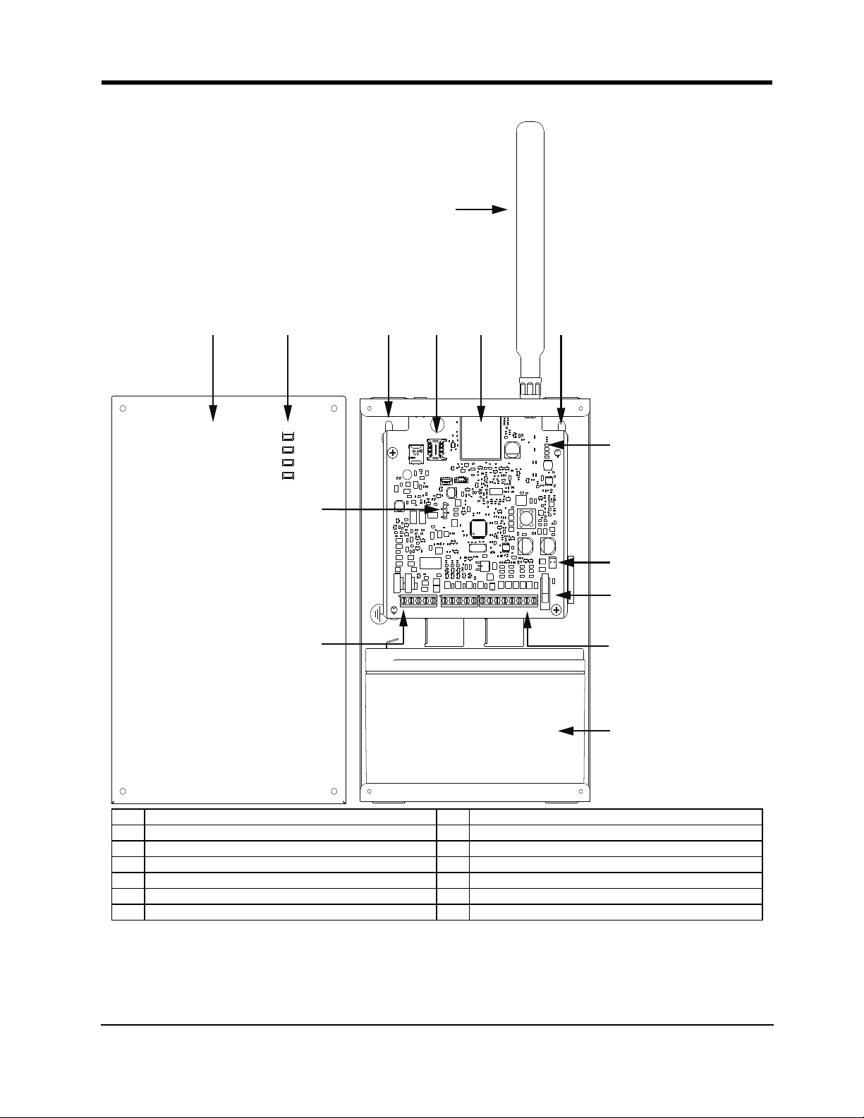
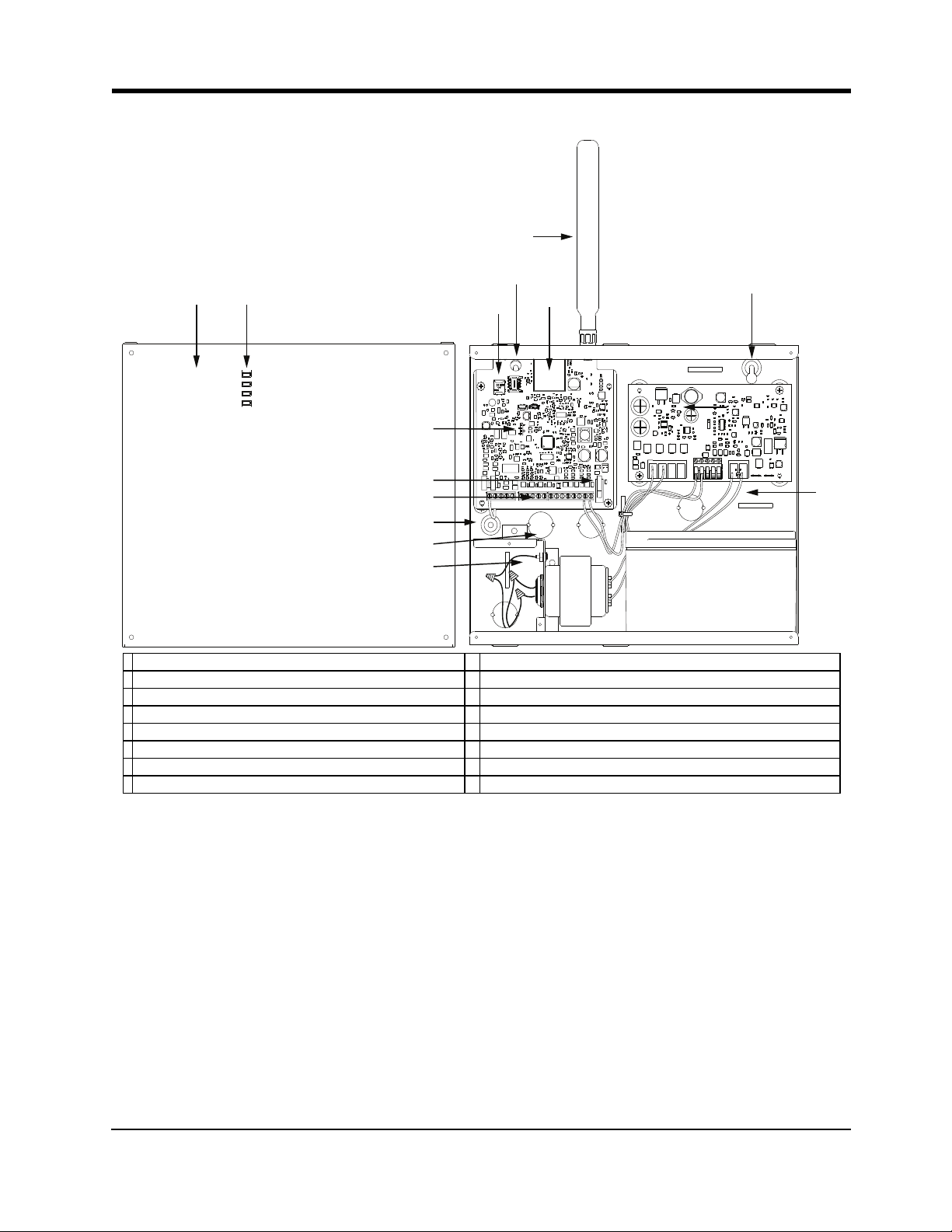
This manual covers two communicator models, the LE4020 and the LE4020CF. They are referred to through-
out this manual as LE4020/LE4020CF unless otherwise indicated.
This LE4020/LE4020CF manages transmissions to a central station and can simulate the landline in the event
of trouble (e.g., landline down) or even substitute the landline completely in areas where the 3G/LTE or 2G
cellular service is provided and a landline is not available.
By connecting a to a control panel's standard PSTN interface, telephone-based Contact ID or SIA signals are
decoded and seamlessly routed through the LTE or 3G network to any of the compatible receiver options.
The LE4020/LE4020CF are wireless communicators for UL/ULC commercial fire and/or burglary applications.
Both models send alarm system information to a Sur-Gard System I-IP, II, III, IV or 5 receiver. The
LE4020/LE4020CF uses the LTE or 3G wireless network. The LE4020/LE4020CF can be used with UL/ULC
Listed compatible control units, as indicated in the manufacturer's installation instructions.
Note: These communicators are designed to work with the Contact ID communication format as described in
the SIA DC-05 standard and the SIA DC-03 standard for 300 baud. Before completing the field installation of
the alarm monitoring system please ensure communication with the supervising central station is successful by
sending several events and getting confirmation that they have been received.
1.1 Features
lDual-band UMTS/HSPA; Penta-Band LTE (LE4020/LE4020CF)
lAdvanced Carrier Selection
lBi-color Wireless Signal Strength Indicator
lLTE or 3G Internet communication with Sur-Gard SG-System I-IP / II / III / IV / 5
lCompatible with listed alarm control panels that have an integrated DACT and support a 4-digit or 10-
digit Contact ID communication format as described in SIA DC-05 Standard and the SIA DC-03 stand-
ard for 300 baud. Example of suitable compatible alarm panels:
DSC Models PC1864, PC1832, PC1616, PC4020. For LE4020/LE4020CF, the following alarm panels
are also compatible: HS2128, HS2064, HS2032, HS2016, HS3128, HS3032
lPanel Transmission Monitoring for up to four phone numbers
lSimulates landline
lSwitches automatically to the LTE or 3G cellular network in the event of landline trouble (e.g., line
down)
lFour Programmable (NO/NC/SEOL) Inputs
l12V 7Ah battery (optional, not included for model LE4020. Required for model LE4020CF)
lCase Tamper Input
lLandline overvoltage protection
lFour Programmable Outputs
lDLS support for status, firmware updates and remote debug enable
lRemote Firmware Upgrade
lRemote Diagnostics
lPanel Format Detection
lSMS Command and Control
Note: Feature not evaluated by UL/ULC
lPhone number call direction
lEasy enrollment with C24 Communications via web or mobile interface
1.1.1 Technical Specifications
The input voltage to the LE4020C can be drawn from the UL/ULC Listed control panel or provided by an
external UL/ULC Listed power supply rated for the application (external power-limited source).
LE4020/LE4020CF Installation Manual

5
1.1.1 Technical Specifications
Note: The power supply must be Class 2, Power Limited. For residential applications a suitable power adaptor
is model DSC ADP1310(W)-NA.
Table 1-1 Ratings
Power Supply Ratings LE4020 LE4020CF
Input Voltage:
10 Vdc to 28 Vdc (use separately listed con-
trol panel or power supply) or use DSC
ADP1310/1320(W)-NA power adapter with
battery 12V/7Ah
120 Vac/60Hz
Current Consumption
Average Transmitter PWB Current: 140 mA* (with PSTNconnected)
155 mA* (without PSTNconnected)
PWBTransmission Current: 225 mA*
Rated Current:
500 mA using listed control panel or power
supply
700 mA using power adapter
0.3 A
* Plus any current drawn from the LE4020/LE4020CF AUX+ terminal (200 mA). Each of the four PGM outputs can be loaded up to 50 mA
(max)
Working Voltage Range
With Battery: Use the DSCADP1310/1320(W)-NA power
adapter Use internal PS4085 power supply module
Without Battery: 10 Vdc to 28 Vdc (external power supply N/A
Battery Type: sealed, rechargeable type, rated 12 V / 7 Ah (for 24 hr standby time plus 5 min alarm)
Battery charging voltage: 13.75 Vdc
Battery charge current limit: 360 mA 700 mA
NOTE: Battery must be replaced every 3 to 5 years.
NOTE: When using the battery, use DSC ADP1310(W)-NA power adapter.
Operating frequency - 3G (UMTS/HSPA): 850 MHz / 1900 MHz
For LE4020 operating frequencies, see Table 1.2.
Antenna gain: 2.0 dBi
Environmental Specifications
Operating temperature: 0°C-49°C (32°F-120°F)
Humidity: 93%RH Maximum (non-condensing)
Mechanical Specifications
White cabinet dimensions: 257.2 mm x 161.9 mm x 76.6 mm / 10.125” x 6.375” x 3.0”
Weight (without battery): 1.28 kg / 2.8 lb
Red cabinet dimensions: 295.3 mm x 258.4 mm x 77.0 mm / 11.625” x 10.175” x 3.03”
Weight (without battery): 2.52 kg / 5.5 lb
Simulated Telco Loop specifications (TIP/RING)
On-Hook Voltage: 12 Vdc
Off-Hook Voltage (Maximum): 35 Vdc
Loop Current: 25 mA
Loop Resistance: 600 Ohms
Other manuals for LE4020
1
This manual suits for next models
1
Table of contents
Other DSC Cell Phone manuals

DSC
DSC GS2060 User manual

DSC
DSC neo Power Series User manual

DSC
DSC 3G4010 User manual

DSC
DSC TL2803GR User manual

DSC
DSC 3G2080 User manual

DSC
DSC GS2060-SM User manual

DSC
DSC 3G4010CF User manual

DSC
DSC PowerSeries Neo TL280LER User manual

DSC
DSC 3G2060 User manual

DSC
DSC Skyroute CL3050 ver 1.2 Operating instructions