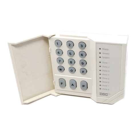
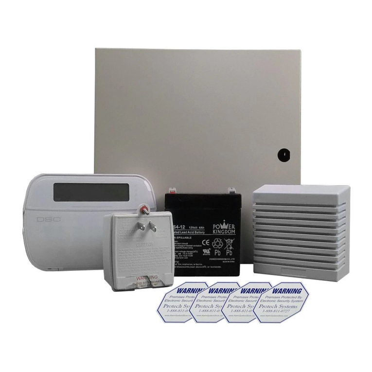
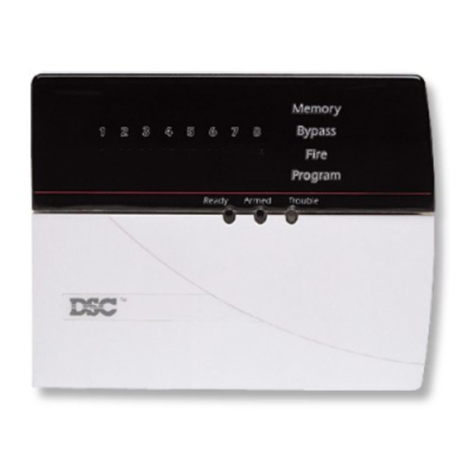
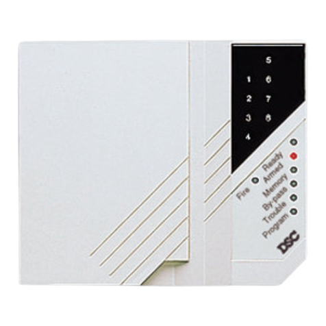
DSC PDigital Security PC1565 User manual

Installation
Manual
WARNING
This manual contains information on limitations regarding product use and function and information on the
limitations as to liability of the manufacturer. The entire manual should be carefully read.
Software Version 2.1DJRU
DLS-1 v6.6P and higher

WARNING Please Read Carefully
1RWHWR,QVWDOOHUV
This warning contains vital information. As the only individual in contact with system users, it is your
responsibility to bring each item in this warning to the attention of the users of this system.
6\VWHP)DLOXUHV
This system has been carefully designed to be as effective as possible. There are circumstances, however,
involving fire, burglary, or other types of emergencies where it may not provide protection. Any alarm sys-
tem of any type may be compromised deliberately or may fail to operate as expected for a variety of reasons.
Some but not all of these reasons may be:
Inadequate Installation
A security system must be installed properly in order to provide adequate protection. Every installation
should be evaluated by a security professional to ensure that all access points and areas are covered. Locks
and latches on windows and doors must be secure and operate as intended. Windows, doors, walls, ceilings
and other building materials must be of sufficient strength and construction to provide the level of protection
expected. A reevaluation must be done during and after any construction activity. An evaluation by the fire
and/or police department is highly recommended if this service is available.
Criminal Knowledge
This system contains security features which were known to be effective at the time of manufacture. It is
possible for persons with criminal intent to develop techniques which reduce the effectiveness of these fea-
tures. It is important that a security system be reviewed periodically to ensure that its features remain effec-
tive and that it be updated or replaced if it is found that it does not provide the protection expected.
Access by Intruders
Intruders may enter through an unprotected access point, circumvent a sensing device, evade detection by
moving through an area of insufficient coverage, disconnect a warning device, or interfere with or prevent
the proper operation of the system.
Power Failure
Control units, intrusion detectors, smoke detectors and many other security devices require an adequate
power supply for proper operation. If a device operates from batteries, it is possible for the batteries to fail.
Even if the batteries have not failed, they must be charged, in good condition and installed correctly. If a
device operates only by AC power, any interruption, however brief, will render that device inoperative while
it does not have power. Power interruptions of any length are often accompanied by voltage fluctuations
which may damage electronic equipment such as a security system. After a power interruption has occurred,
immediately conduct a complete system test to ensure that the system operates as intended.
Failure of Replaceable Batteries
This system’s wireless transmitters have been designed to provide several years of battery life under normal
conditions. The expected battery life is a function of the device environment, usage and type. Ambient con-
ditions such as high humidity, high or low temperatures, or large temperature fluctuations may reduce the
expected battery life. While each transmitting device has a low battery monitor which identifies when the
batteries need to be replaced, this monitor may fail to operate as expected. Regular testing and maintenance
will keep the system in good operating condition.
Compromise of Radio Frequency (Wireless) Devices
Signals may not reach the receiver under all circumstances which could include metal objects placed on or
near the radio path or deliberate jamming or other inadvertent radio signal interference.
System Users
A user may not be able to operate a panic or emergency switch possibly due to permanent or temporary
physical disability, inability to reach the device in time, or unfamiliarity with the correct operation. It is
important that all system users be trained in the correct operation of the alarm system and that they know
how to respond when the system indicates an alarm.
Smoke Detectors
Smoke detectors that are a part of this system may not properly alert occupants of a fire for a number of rea-
sons, some of which follow. The smoke detectors may have been improperly installed or positioned. Smoke
may not be able to reach the smoke detectors, such as when the fire is in a chimney, walls or roofs, or on the
other side of closed doors. Smoke detectors may not detect smoke from fires on another level of the resi-
dence or building.
Every fire is different in the amount of smoke produced and the rate of burning. Smoke detectors cannot
sense all types of fires equally well. Smoke detectors may not provide timely warning of fires caused by
carelessness or safety hazards such as smoking in bed, violent explosions, escaping gas, improper storage of
flammable materials, overloaded electrical circuits, children playing with matches or arson.
Even if the smoke detector operates as intended, there may be circumstances when there is insufficient warn-
ing to allow all occupants to escape in time to avoid injury or death.
Motion Detectors
Motion detectors can only detect motion within the designated areas as shown in their respective installation
instructions. They cannot discriminate between intruders and intended occupants. Motion detectors do not
provide volumetric area protection. They have multiple beams of detection and motion can only be detected
in unobstructed areas covered by these beams. They cannot detect motion which occurs behind walls, ceil-
ings, floor, closed doors, glass partitions, glass doors or windows. Any type of tampering whether intentional
or unintentional such as masking, painting, or spraying of any material on the lenses, mirrors, windows or
any other part of the detection system will impair its proper operation.
Passive infrared motion detectors operate by sensing changes in temperature. However their effectiveness
can be reduced when the ambient temperature rises near or above body temperature or if there are intentional
or unintentional sources of heat in or near the detection area. Some of these heat sources could be heaters,
radiators, stoves, barbeques, fireplaces, sunlight, steam vents, lighting and so on.
Warning Devices
Warning devices such as sirens, bells, horns, or strobes may not warn people or waken someone sleeping if
there is an intervening wall or door. If warning devices are located on a different level of the residence or
premise, then it is less likely that the occupants will be alerted or awakened. Audible warning devices may
be interfered with by other noise sources such as stereos, radios, televisions, air conditioners or other appli-
ances, or passing traffic. Audible warning devices, however loud, may not be heard by a hearing-impaired
person.
Telephone Lines
If telephone lines are used to transmit alarms, they may be out of service or busy for certain periods of time.
Also an intruder may cut the telephone line or defeat its operation by more sophisticated means which may
be difficult to detect.
Insufficient Time
There may be circumstances when the system will operate as intended, yet the occupants will not be pro-
tected from the emergency due to their inability to respond to the warnings in a timely manner. If the system
is monitored, the response may not occur in time to protect the occupants or their belongings.
Component Failure
Although every effort has been made to make this system as reliable as possible, the system may fail to func-
tion as intended due to the failure of a component.
Inadequate Testing
Most problems that would prevent an alarm system from operating as intended can be found by regular test-
ing and maintenance. The complete system should be tested weekly and immediately after a break-in, an
attempted break-in, a fire, a storm, an earthquake, an accident, or any kind of construction activity inside or
outside the premises. The testing should include all sensing devices, keypads, consoles, alarm indicating
devices and any other operational devices that are part of the system.
Security and Insurance
Regardless of its capabilities, an alarm system is not a substitute for property or life insurance. An alarm sys-
tem also is not a substitute for property owners, renters, or other occupants to act prudently to prevent or
minimize the harmful effects of an emergency situation.
Limited Warranty
Digital Security Controls Ltd. warrants the original purchaser that for a period of twelve months from the
date of purchase, the product shall be free of defects in materials and workmanship under normal use. Dur-
ing the warranty period, Digital Security Controls Ltd. shall, at its option, repair or replace any defective
product upon return of the product to its factory, at no charge for labour and materials. Any replacement and/
or repaired parts are warranted for the remainder of the original warranty or ninety (90) days, whichever is
longer. The original purchaser must promptly notify Digital Security Controls Ltd. in writing that there is
defect in material or workmanship, such written notice to be received in all events prior to expiration of the
warranty period. There is absolutely no warranty on software and all software products are sold as a user
license under the terms of the software license agreement included with the product. The Customer assumes
all responsibility for the proper selection, installation, operation and maintenance of any products purchased
from DSC. Custom products are only warranted to the extent that they do not function upon delivery. In
such cases, DSC can replace or credit at its option.
,QWHUQDWLRQDO:DUUDQW\
The warranty for international customers is the same as for any customer within Canada and the United
States, with the exception that Digital Security Controls Ltd. shall not be responsible for any customs fees,
taxes, or VAT that may be due.
:DUUDQW\3URFHGXUH
To obtain service under this warranty, please return the item(s) in question to the point of purchase. All
authorized distributors and dealers have a warranty program. Anyone returning goods to Digital Security
Controls Ltd. must first obtain an authorization number. Digital Security Controls Ltd. will not accept any
shipment whatsoever for which prior authorization has not been obtained.
&RQGLWLRQVWR9RLG:DUUDQW\
This warranty applies only to defects in parts and workmanship relating to normal use. It does not cover:
• damage incurred in shipping or handling;
• damage caused by disaster such as fire, flood, wind, earthquake or lightning;
• damage due to causes beyond the control of Digital Security Controls Ltd. such as excessive voltage,
mechanical shock or water damage;
• damage caused by unauthorized attachment, alterations, modifications or foreign objects;
• damage caused by peripherals (unless such peripherals were supplied by Digital Security Controls
Ltd.);
• defects caused by failure to provide a suitable installation environment for the products;
• damage caused by use of the products for purposes other than those for which it was designed;
• damage from improper maintenance;
• damage arising out of any other abuse, mishandling or improper application of the products.
,WHPV1RW&RYHUHGE\:DUUDQW\
In addition to the items which void the Warranty, the following items shall not be covered by Warranty: (i)
freight cost to the repair centre; (ii) products which are not identified with DSC's product label and lot num-
ber or serial number; (iii) products disassembled or repaired in such a manner as to adversely affect perfor-
mance or prevent adequate inspection or testing to verify any warranty claim. Access cards or tags returned
for replacement under warranty will be credited or replaced at DSC's option. Products not covered by this
warranty, or otherwise out of warranty due to age, misuse, or damage shall be evaluated, and a repair esti-
mate shall be provided. No repair work will be performed until a valid purchase order is received from the
Customer and a Return Merchandise Authorisation number (RMA) is issued by DSC's Customer Service.
Digital Security Controls Ltd.’s liability for failure to repair the product under this warranty after a reason-
able number of attempts will be limited to a replacement of the product, as the exclusive remedy for breach
of warranty. Under no circumstances shall Digital Security Controls Ltd. be liable for any special, incidental,
or consequential damages based upon breach of warranty, breach of contract, negligence, strict liability, or
any other legal theory. Such damages include, but are not limited to, loss of profits, loss of the product or any
associated equipment, cost of capital, cost of substitute or replacement equipment, facilities or services,
down time, purchaser’s time, the claims of third parties, including customers, and injury to property. The
laws of some jurisdictions limit or do not allow the disclaimer of consequential damages. If the laws of such
a jurisdiction apply to any claim by or against DSC, the limitations and disclaimers contained here shall be
to the greatest extent permitted by law. Some states do not allow the exclusion or limitation of incidental or
consequential damages, so that the above may not apply to you.
'LVFODLPHURI:DUUDQWLHV
This warranty contains the entire warranty and shall be in lieu of any and all other warranties, whether
expressed or implied (including all implied warranties of merchantability or fitness for a particular purpose)
and of all other obligations or liabilities on the part of Digital Security Controls Ltd. Digital Security Con-
trols Ltd. neither assumes responsibility for, nor authorizes any other person purporting to act on its behalf to
modify or to change this warranty, nor to assume for it any other warranty or liability concerning this prod-
uct. This disclaimer of warranties and limited warranty are governed by the laws of the province of Ontario,
Canada.
WARNING: Digital Security Controls Ltd. recommends that the entire system be completely tested on a
regular basis. However, despite frequent testing, and due to, but not limited to, criminal tampering or electri-
cal disruption, it is possible for this product to fail to perform as expected.
2XWRI:DUUDQW\5HSDLUV
Digital Security Controls Ltd. will at its option repair or replace out-of-warranty products which are returned
to its factory according to the following conditions. Anyone returning goods to Digital Security Controls
Ltd. must first obtain an authorization number. Digital Security Controls Ltd. will not accept any shipment
whatsoever for which prior authorization has not been obtained.
Products which Digital Security Controls Ltd. determines to be repairable will be repaired and returned. A
set fee which Digital Security Controls Ltd. has predetermined and which may be revised from time to time,
will be charged for each unit repaired.
Products which Digital Security Controls Ltd. determines not to be repairable will be replaced by the nearest
equivalent product available at that time. The current market price of the replacement product will be
charged for each replacement unit.
L
7DEOHRI&RQWHQWV
Section 1: System Introduction 1
6SHFLILFDWLRQV
$GGLWLRQDO'HYLFHV
2XWRIWKH%R[
Section 2: Getting Started 3
,QVWDOODWLRQ6WHSV
7HU LQDO'HVFULSWLRQV
.H\EXV2SHUDWLRQDQG:LULQJ
&XUUHQW5DWLQJV²0RGXOHVDQG$FFHVVRULHV
.H\SDG$VVLJQ HQW
6XSHUYLVLRQ
5H RYLQJ0RGXOHV
=RQH:LULQJ
)LUH=RQH:LULQJ
+U$X[LOLDU\,QSXW:LULQJ3*0
.H\SDG=RQHV
Section 3: Keypad Commands 7
$U LQJDQG'LVDU LQJ
$XWR%\SDVV²6WD\$U LQJ
$XWR DWLF$U LQJ
>@&R DQGV
)XQFWLRQ.H\V
)HDWXUHV$YDLODEOHIRUWKH/&'=
Section 4: How to Program 11
,QVWDOOHU·V3URJUD LQJ
3URJUD LQJ'HFL DO'DWD
3URJUD LQJ+(;'DWD
3URJUD LQJ7RJJOH2SWLRQ6HFWLRQV
9LHZLQJ3URJUD LQJ
Section 5: Program Descriptions 13
3URJUD LQJ6HFXULW\&RGHV
=RQH3URJUD LQJ
=RQH$WWULEXWHV
$VVLJQLQJ.H\SDG=RQHV
&R XQLFDWRU²'LDOLQJ
&R XQLFDWRU²$FFRXQW1X EHUV
&R XQLFDWRU²7HOHSKRQH1X EHUV
&R XQLFDWRU²5HSRUWLQJ&RGHV
&R XQLFDWRU²5HSRUWLQJ)RU DWV
'RZQORDGLQJ
3*02XWSXW2SWLRQV
7HOHSKRQH/LQH0RQLWRU7/0
%HOO
7HVW7UDQV LVVLRQ
7UDQV LVVLRQ'HOD\
)LUH$X[LOLDU\DQG3DQLF.H\V
$U LQJ'LVDU LQJ2SWLRQV
(QWU\([LW'HOD\2SWLRQV
6ZLQJHU6KXWGRZQ
(YHQW%XIIHU
.H\SDG/RFNRXW2SWLRQV
.H\SDG%ODQNLQJ
.H\SDG%DFNOLJKWLQJ
/RRS5HVSRQVH
.H\SDG7D SHUV
$GGLWLRQDO6\VWH 0RGXOHV
(QJLQHHUV5HVHW
&ORFN$GMXVW
7L HEDVH
5HVHWWLQJ)DFWRU\'HIDXOWV
,QVWDOOHU·V/RFNRXW
:DON7HVW,QVWDOOHU
Section 6: Programming Worksheets 26
Appendix A: Reporting Codes 39
Appendix B: Programming LCD5500 Keypads 41
Appendix C: Programming LCD5501Z Keypads 48

ii
PC1565 Wiring Diagram

6HFWLRQ6\VWH ,QWURGXFWLRQ
1.1 Specifications
Downloading Software Support
• PC1565 v2.1DJRU uses DLS-1 v6.6P and higher.
Flexible Zone Configuration
• Six fully programmable zones; system expandable to
eight zones using keypad zone inputs and wireless
zones
• 38 access codes: one master code, one maintenance
code, two duress codes, two supervision codes and 32
general access codes
• 28 zone types; 8 programmable zone attributes
• Normally closed, single EOL and double EOL zone wiring
• Eight wireless zones available using the PC5132 Wireless
Receiver
Audible Alarm Output
• 700mA Supervised Bell Output (current limited at 3
amps), 12Vdc
• Steady or Pulsed Output
EEPROM Memory
• Does not lose programming or system status on com-
plete AC and Battery failure
Programmable Outputs
• One programmable voltage output and one programma-
ble voltage output/input; 20 programmable options
• PGM1 = 300mA; PGM2 = 50mA
Powerful 1.5 Amp Regulated Power Supply
• 550 mA Auxiliary Supply, 12 VDC
• Positive Temperature Coefficient (PTC) components
replace fuses
• Supervision for loss of AC power, low battery
Power Requirements
• Transformer = 16 VAC, 40VA (Secondary)
• Battery = 12V 4Ah minimum rechargeable sealed lead
acid battery (battery not supplied by DSC).
Remote Keypad Specifications
• Three keypads available:
- PC1555RKZ eight zone LED keypad with zone input
- PC5508Z eight zone LED keypad with zone input
- LCD5500Z alphanumeric keypad with zone input
- LCD5501Z fixed message LCD keypad with zone input
- LCD5501ZT32-433 keypad / receiver
• All keypads have five programmable function keys
• Connect up to eight keypads
• 4-wire (Quad) connection to Keybus
• Built in piezoelectric buzzer
Digital Communicator Specifications
• Supports major communication formats including SIA
and Contact ID
• Event-initiated personal paging
• Three programmable telephone numbers
• Two account numbers
• Supports LINKS2X50 Long Range Radio Transmitter
• DTMF and pulse dialing
• DPDT line seizure
• Anti-jam feature
• Split reporting of selected transmissions to each tele-
phone number
System Supervision Features
The PC1565 continuously monitors a number of possible trou-
ble conditions including:
• AC power failure • AUX Power Supply Trouble
• Fault by zone • Loss of internal clock
• Tamper by zone • Bell output trouble
• Fire trouble • Telephone line trouble
• Failure to communicate • Low battery condition (panel)
• Low battery by device (wireless)
• Module fault (supervisory or tamper)
False Alarm Prevention Features
• Audible Exit Delay • Quick Exit
• Audible Exit Fault • Cross Zone Burglary Alarm
• Communication Delay • Rotating Keypress Buffer
• Urgency on Entry Delay
Additional Features
• Auto Arm at specified time
• Keypad-activated alarm output and communicator test
• All modules connect to the system via a four wire Keybus
up to 1000’/305m from main panel
• An event buffer which records the past 128 events with
both the time and date at which they occurred; buffer can
be printed using PC5400 serial interface module, or
viewed with the LCD5500Z keypad.
• Supports the addition of the PC5132 wireless receiver for
integration of wireless devices
• Uploading and downloading capability
• Local downloading capability through the use of the
PC-LINK adaptor
• Added Keybus fault protection: clock and data outputs
have been programmed to withstand shorts to +12v to
prevent control panel damage

1.2 Additional Devices
In addition to the information below, see the back cover for a
DSC module compatibility table.
PC5132 Wireless Receiver
The PC5132 Wireless Receiver can be used to connect up to
8 wireless devices to the system. All devices are narrow band,
433MHz, fully supervised devices.
The devices available are as follows:
:/6/:/63/:LUHOHVV0RWLRQ'HWHFWRU
:/6:LUHOHVV6PRNH'HWHFWRU
:/6:/6:LUHOHVV.H\
:/6/0LQL'RRU:LQGRZ RQWDFW
For more information on these wireless devices, please refer
to the individual Installation Instructions.
PC5400 Printer Module
The PC5400 Printer Module allows the panel to print out all
events that occur on the system to any serial printer. The print-
out will contain the time, date and the event that occurred.
Cabinets
Several different cabinets are available for the PC1565 mod-
ules. They are as follows:
6SHFLDO38 DELQHW
Main control cabinet for the PC1565 main panel. Dimensions
318mm x 318mm x 102mm / 12.5” x 12.5” x 4” approximately.
1.3 Out of the Box
Please verify that the following components are included in
your system:
• one PUC-1 cabinet
• one PC1565 main control circuit board
• one PC1555RKZ keypad with zone input
• one Installation Manual with programming worksheets
• one Instruction Manual for the end user
• one hardware pack consisting of:
- one mylar cabinet label
- four plastic circuit board standoffs
- sixteen 5600Ω(5.6K) resistors
- one 2200Ω(2.2K) resistor
- one 1000Ω(1K) resistor
- ground connection assembly
- one cabinet door plug
(QYLURQPHQWDO,QVWUXFWLRQV
$WWKHHQGRIOLIHRIWKLVHTXLSPHQWDQGRUGXULQJUHSDLUV'2127',6326(DQ (OHFWULFDODQGRU(OHFWURQLFHTXLS
PHQWSDUWV$6816257('081,&,3$/:$67($OORIWKHVH0867%(FROOHFWHG6(3$5$7(/<DVSHUWKHORFDO
5XOHVDQGRU5HJXODWLRQV
$WWKHHQGRIOLIHRIWKLVHTXLSPHQW5(7851,7WRWKH',675,%8725,QWKLVPDQQHU RXZLOODFWLYHO FRQWULEXWH
WRD&/($1(5DQG6$)(5(19,5210(17
7KHGLVSRVDORIWKHHTXLSPHQWRUSDUWVRILWZLWKLQWKHXQVRUWHG081,&,3$/:$67(PD FRQWULEXWHWRLQWURGXFH
KD]DUGRXVVXEVWDQFHVZLWKLQWKH(19,5210(17DQGLWPD DIIHFWWKH+80$1+($/7+
7KH6<0%2/WKDWLVPDUNHG21WKH(48,30(17DQGRU21WKH3$&.$*,1*PHDQVWKDW7+,6(48,30(17
DQGRUSDUWVRILWVKDOO127%(',6326('DWWKHHQGRIOLIHRIWKHSURGXFWSDUWLQWKH081,&,3$/:$67(,W
PHDQVWKDWHOHFWULFDODQGHOHFWURQLFHTXLSPHQWZDVWHVKRXOGEHGLVSRVHGDVD727$//<6(3$5$7(&2//(&7,21

6HFWLRQ*HWWLQJ6WDUWHG
The following sections provide a thorough description of how
to wire and configure devices and zones.
2.1 Installation Steps
Read this section completely before you begin. Once you
have an overall understanding of the installation process,
carefully work through each step.
Step 1: Create a Layout
Draw a rough sketch of the building to get an idea of where all
alarm detection devices, keypads and other modules are to
be located.
Step 2: Mounting the Panel
Mount the panel in a dry area close to an unswitched AC
power source and the incoming telephone line. Before attach-
ing the cabinet to the wall, be sure to press the four circuit-
board mounting studs into the cabinet from the back. After
you have attached the cabinet to the wall, stick the provided
DSC logo sticker on the front of the cabinet.
127( <RX PXVW FRPSOHWH DOO ZLULQJ EHIRUH FRQQHFWLQJ WKH
EDWWHU\RUDSSO\LQJ$&WRWKHSDQHO
Step 3: Wiring the Keybus (Section 2.3)
Wire the Keybus to each of the modules following the guide-
lines provided in section 2.3 of this manual.
Step 4: Zone Wiring (Section 2.8)
You must power down the control panel to complete all zone
wiring. Please refer to section 2.8 “Zone Wiring” on page 5
when connecting zones using normally closed loops, single
EOL resistors, double EOL resistors, Fire zones and Key-
switch Arming zones.
Step 5: Complete Wiring (Section 2.2)
Complete all other wiring including bells or sirens, telephone
line connections, and ground connections following the guide-
lines provided in section 2.2.
Step 6: Power up the Control
Once all zone and Keybus wiring is complete, power up the
control panel. First, connect the red battery lead to the posi-
tive terminal and the black lead to negative. Then, connect the
AC.
127( &RQQHFW WKH EDWWHU\ EHIRUH FRQQHFWLQJ WKH $& 7KH
SDQHOZLOOQRWSRZHUXSRQWKHEDWWHU\FRQQHFWLRQDORQH
Step 7: Keypad Assignment (Section 2.5)
In order for keypads to be properly supervised, each must be
assigned to a different address. Please follow the guidelines
provided in Section 2.5 when assigning keypads.
Step 8: Supervision (Section 2.6)
The supervision of each module by the panel is automatically
enabled upon power up. Please verify that all modules appear
on the system according to the instructions in section 2.6.
Step 9: Programming the System (Sections 4 & 5)
Section 4 explains how to program the panel. Section 5 con-
tains a complete description of the various programmable fea-
tures, which options are available and how they function. Fill
out the Programming Worksheets completely before attempt-
ing to program the system.
Step 10: Testing the System
Test the panel thoroughly to ensure that all features and func-
tions are operating as programmed.
2.2 Terminal Descriptions
Battery Connection
A 12V 4Ah rechargeable battery is used as a backup source
of power in the event of an AC power failure. The battery also
provides additional current when the panel’s demands exceed
the power output of the transformer, such as when the panel is
in alarm.
127('RQRWFRQQHFWWKHEDWWHU\XQWLODOORWKHUZLULQJLVFRP
SOHWH&RQQHFWWKHEDWWHU\EHIRUHFRQQHFWLQJWKH$&
Connect the RED battery lead to the positive battery terminal;
connect the BLACK lead to negative.
The +LJK&XUUHQW6WDQGDUG%DWWHU\&KDUJH option (section
[701], option [7]) allows you to choose between a high current
battery charge and the standard battery charge rate.
Enable the $XWRPDWLF %DWWHU\ &KHFN option to have the
panel perform a 10 second battery test upon disarming and at
1200h (noon).
127(7KHSDQHOZLOOQRWSHUIRUPWKH$XWRPDWLF%DWWHU\&KHFN
LIWKHUHLVQR$&SUHVHQWRQWKHV\VWHP
High Current /Standard Battery Charge . . .Section [701]: [7]
Automatic Battery Check . . . . . . . . . . . . . . .Section [018]: [3]
AC Terminals – AC
The panel requires a 16.5VAC, 40VA transformer. Connect the
transformer to an unswitched AC source and connect the
transformer to these terminals.
The panel can be programmed to accept a power line fre-
quency of either 50Hz AC or 60Hz AC in programming section
[701], option [1].
127('RQRWFRQQHFWWKHWUDQVIRUPHUXQWLODOORWKHUZLULQJLV
FRPSOHWH
Auxiliary Power Terminals – AUX+ and AUX-
These terminals provide up to 550 mA of additional current at
12 VDC for devices requiring power. Connect the positive side
of any device requiring power to the AUX+ terminal, the nega-
tive side to AUX- (ground). The AUX output is protected. This
means that if too much current is drawn from these terminals
(such as a wiring short), the panel will temporarily shut off the
output until the problem is corrected.
Bell Output Terminals – BELL+ and BELL-
These terminals provide up to 700 mA of continuous current at
12 VDC for powering bells, sirens, strobes or other warning-
type equipment. Connect the positive side of any alarm warn-
ing device to BELL+, the negative side to BELL–. Please note
that the Bell output is protected: if too much current is drawn
from these terminals (such as a wiring short), the Bell PTC will
open. Three amps can be drawn for short periods only.
The Bell output is supervised. If no alarm warning devices are
in use, connect a 1000Ωresistor across BELL+ and BELL– to
prevent the panel from displaying a trouble condition. For
more information, please refer to section 3.4 “[*] Commands”
on page 7.

Keybus Terminals – AUX+, AUX-, YEL, GRN
The Keybus is used by the panel to communicate with mod-
ules and vice versa. Each module has four Keybus terminals
that must be connected to the four Keybus terminals on the
panel. For more information, see section 2.3 “Keybus Opera-
tion and Wiring”.
Programmable Output Terminals – PGM1 and PGM2
Each PGM output is designed so that when activated by the
panel, the terminal will switch to ground.
PGM1 can sink up to 300mA of
current. Connect the positive
side of the LED or buzzer to
AUX+, the negative side to
PGM1. If more than 300 mA of
current are required, a relay
must be used. Please study
PGM wiring in the accompany-
ing diagram.
PGM2 operates similarly to
PGM1. However, PGM2 can
only sink up to 50mA of cur-
rent. For a list of the program-
mable output options, see
section 5.11 “PGM Output
Options” on page 19.
Zone Input Terminals – Z1 to Z6
Each detection device must be connected to a zone on the
control panel. We suggest that one detection device be con-
nected to each zone; wiring multiple detection devices to a
single zone, however, is possible. For zone wiring specifics,
please see section 2.8 “Zone Wiring” on page 5.
Telephone Connection Terminals – TIP, RING, T-1, R-1
If a telephone line is required for central station communica-
tion or downloading, connect an RJ-31X telephone jack in the
following manner:
127( )RUSURSHURSHUDWLRQQRRWKHUWHOHSKRQHH XLSPHQW
VKRXOGEH FRQQHFWHGEHWZHHQWKHFRQWUROSDQHODQGWKH WHOH
SKRQHFRPSDQ\IDFLOLWLHV'RQRWFRQQHFWWKHDODUPSDQHOFRP
PXQLFDWRU WR WHOHSKRQH OLQHV LQWHQGHG IRU XVH ZLWK D ID[
PDFKLQH7KHVHOLQHVPD\LQFRUSRUDWHDYRLFHILOWHUZKLFKGLV
FRQQHFWV WKH OLQH LI DQ\WKLQJ RWKHU WKDQ ID[ VLJQDOV DUH
GHWHFWHGUHVXOWLQJLQLQFRPSOHWHWUDQVPLVVLRQV
2.3 Keybus Operation and Wiring
The Keybus is used by the panel to communicate with all
connected modules and vice versa. The red (AUX+) and
black (AUX-) terminals are used to provide power, while the
yellow (YEL) and green (GRN) terminals are clock and data
respectively.
127(7KHIRXU.H\EXVWHUPLQDOV RI WKH SDQHO PXVW EH FRQ
QHFWHGWRWKHIRXU.H\EXVWHUPLQDOVRUZLUHVRIDOOPRGXOHV
The following restrictions apply to Keybus wiring:
• Keybus should be run in minimum 22 gauge quad
(0.5mm); two pair twist is preferred.
• The modules should be home-run to the panel but can be
connected in series or T-tapped.
• Any module can be connected anywhere along the Key-
bus. You do not need to run a separate Keybus wire for
keypads, etc.
• No module can be more than 1,000'/305m (in wire length)
from the panel.
• Shielded wire should not be used.
([DPSOHRI.H\EXV:LULQJ
NOTE:
Module (A) is correctly
wired within 1,000'/305m
of wire from the panel.
Module (B) is correctly
wired within 1,000'/305m
of wire from the panel.
Module (C) is NOT wired
correctly as it is further
than 1,000'/305m from the panel, in wire distance.
2.4 Current Ratings – Modules and
Accessories
In order for the PC1565 system to operate properly, the power
output capabilities of the main control and the expansion
devices must not be exceeded. Use the data presented below
to ensure that no part of the system is overloaded and cannot
function properly.
PC1565 (12 VDC)
AUX+: ........550mA: Subtract the listed rating for each key-
pad, expansion module and accessory con-
nected to AUX+ or Keybus.
BELL: .........700mA continuous rating; 3.0A short term. Avail-
able only with standby battery connected.
PC1565 Device Ratings (at 12 VDC)
• LCD5500Z Keypad: 85mA
• LCD5501Z Keypad: 90mA
• LCD5501Z32-433T Keypad: 260mA
• PC1555RKZ Keypad: 85mA
• PC5508Z Keypad: 75-85mA
• PC5400 Serial Module: 65mA
• PC5132 Wireless Receiver: 125mA
Other Devices
Please read the manufacturer’s literature carefully to deter-
mine the maximum current requirements for each device—
during activation or alarm—and include the proper values for
loading calculations. Connected devices must not exceed
system capabilities during any possible operational mode.
2.5 Keypad Assignment
There are eight available addresses for keypads. LED key-
pads by default are always assigned to address 1. LCD5500Z
keypads are always assigned to address 8. You will need to
assign each keypad to its own address (1 to 8). Keypad
assignment is required, as it tells the panel which addresses
are occupied. The panel can then generate a fault when a
keypad supervisory is not present.
127( 2QH /&' NH\SDG PXVW EH DVVLJQHG WR DGGUHVV LQ
RUGHUWRXSORDGNH\SDGSURJUDPPLQJXVLQJ'/6VRIWZDUH
How to Assign Keypads
Do the following at each keypad installed on the system:
1. Enter [*][8][installer’s code] to go to installer programming
2. Enter [000] for Keypad Programming

Getting Started: 2.6 Supervision
3. Enter [0] for Address Assignment
4. Enter a two digit number (11-18) to specify which supervi-
sory address the keypad will occupy.
5. Press [#] twice to exit installer programming.
After assigning all keypads, perform a supervisory reset by
entering section [902] in installer’s programming. The panel
will now supervise all assigned keypads and enrolled modules
on the system.
How to Program Function Keys
By default, the 5 function keys on each keypad are pro-
grammed as Stay Arm (03), Away Arm (04), Chime (06), Sen-
sor Reset (14) and Quick Exit (16). You can change the
function of each key on every keypad:
1. Go to the keypad where you want to change the function
key programming and enter Installer Programming.
2. Press [000] for Keypad Programming.
3. Enter [1] to [5] to select a function key to program.
4. Enter the 2 digit number, [00] to [17] to select the feature
you want the function key to have. For a complete list of
Function Key options see section 3.5 “Function Keys” on
page 10.
5. Continue from step 3 until all function keys are pro-
grammed.
6. To exit Installer Programming, press [#] twice.
2.6 Supervision
By default, all modules are supervised upon installation.
Supervision is enabled at all times so that the panel can indi-
cate a trouble if a module is removed from the system.
To check on which modules are currently connected and
supervised, enter programming section [903] from installer’s
programming. The LCD keypad will allow you to scroll through
the display of connected modules. A connected module
which does not show as being present will appear as a trouble
condition and the Trouble light on the keypad will turn ON.
This condition may be due to one or more of the following rea-
sons:
• the module is not connected to the Keybus
• there is a Keybus wiring problem
• the module is more than 1,000'/305m from the panel
• the module does not have enough power
For more information regarding module supervision troubles,
please refer to “[*][2] Trouble Display” on page 8.
2.7 Removing Modules
The panel must be instructed to no longer supervise a module
being removed from the system. To remove the module, dis-
connect it from the Keybus and reset the supervision field by
entering [902] in the installer’s programming. The panel will be
reset to recognize and supervise all existing modules on the
system.
2.8 Zone Wiring
For a complete description of the operation of all zone types,
please refer to section 5.2 “Zone Programming” on page 13.
There are several different ways in which zones may be wired,
depending on which programming options have been
selected. The panel can be programmed to supervise nor-
mally closed, End of Line, or Double End of Line loops. Please
refer to the following diagrams to study each type of individu-
ally supervised zone wiring.
127($Q\]RQHSURJUDPPHGIRU)LUHRU+RXU6XSHUYLVRU\
PXVWEHZLUHGZLWKDVLQJOH(QGRI/LQH(2/UHVLVWRUUHJDUG
OHVV RI WKH W\SH RI ]RQH ZLULQJ VXSHUYLVLRQ VHOHFWHG IRU WKH
SDQHOVHFWLRQ>@>@>@6HHVHFWLRQ“Zone Program-
ming”RQSDJH
127(,I\RXFKDQJHWKH]RQHVXSHUYLVLRQRSWLRQVIURP'(2/
WR(2/RUIURP1&WR'(2/VHFWLRQ>@RSWLRQV>@RU>@
\RX VKRXOG SRZHU GRZQ WKH V\VWHP FRPSOHWHO\ DQG WKHQ
SRZHULWEDFNXS,I\RXGR QRWWKH ]RQHVPD\QRWZRUNFRU
UHFWO\
Normally Closed (NC) Loops
To enable normally closed loops, programming section [013],
option [1] must be ON.
127(7KLVRSWLRQVKRXOGRQO\EHVHOHFWHGLI1RUPDOO\&ORVHG
1&GHWHFWLRQGHYLFHVRUFRQWDFWVDUHEHLQJXVHG
Single End Of Line (EOL) Resistors (5600Ω)
To enable panel detection of single end of line resistors, pro-
gramming section [013], options [1] and [2] must be OFF.
127( 7KLV RSWLRQ VKRXOG EH VHOHFWHG LI HLWKHU 1RUPDOO\
&ORVHG1&RU1RUPDOO\2SHQ12GHWHFWLRQGHYLFHVRUFRQ
WDFWVDUHEHLQJXVHG
Double End of Line (DEOL) Resistors
Double End of Line resistors allow the panel to determine if the
zone is in alarm, tampered or faulted.
To enable panel detection of double end of line resistors, pro-
gramming section [013], option [1] must be OFF and option
[2] must be ON.
127( ,I WKH 'RXEOH (2/ VXSHUYLVLRQ RSWLRQ LV HQDEOHG DOO
KDUGZLUH ]RQHV RQ WKH PDLQ SDQHO PXVW EH ZLUHG IRU 'RXEOH
(2/UHVLVWRUVH[FHSWIRU)LUHDQG+RXU6XSHUYLVRU\]RQHV
127('RQRWZLUH'(2/UHVLVWRUVRQNH\SDG]RQHV
127('RQRWXVH'(2/UHVLVWRUVIRU)LUH]RQHVRU+RXU
6XSHUYLVRU\]RQHV'RQRWZLUH)LUH]RQHVWRNH\SDG]RQHWHU
PLQDOVLIWKH'(2/VXSHUYLVLRQRSWLRQLVVHOHFWHG
ANY Z
TERMINAL
ANY COM
TERMINAL
ANY Z
TERMINAL
ANY COM
TERMINAL
2 NORMALLY
CLOSED CONTACTS
WITH NO END-OF-LINE
RESISTOR
NORMALLY CLOSED
CONTACT;
NO END-OF-LINE
RESISTOR

127( 7KLV RSWLRQ FDQ RQO\ EH VHOHFWHG LI 1RUPDOO\ &ORVHG
1&GHWHFWLRQGHYLFHVRUFRQWDFWVDUHEHLQJXVHG
127(2QO\RQH1&FRQWDFWFDQEHFRQQHFWHGWRHDFK]RQH
:LULQJPXOWLSOHGHWHFWLRQGHYLFHVRUFRQWDFWVRQDVLQJOHORRS
LVQRWDOORZHG
The following chart shows zone status under certain condi-
tions:
/RRS5HVLVWDQFH /RRS6WDWXV
0Ω(shorted wire, loop shorted) Fault
5600Ω(contact closed) Secure
Infinite (broken wire, loop open) Tamper
11200Ω(contact open) Violated
End of Line Resistors. . . . . . . . . . . . . . . . . . Section [013]: [1]
Double End of Line Resistors . . . . . . . . . . .Section [013]: [2]
2.9 Fire Zone Wiring
4-Wire Smoke Detectors
All fire zones must be wired according to the following diagram:
2.10 24-Hr Auxiliary Input Wiring (PGM2)
If PGM2 has been programmed for 24-hour operation, the
zone must be wired according to the following diagram:
2.11 Keypad Zones
Each “z”keypad on the system has a zone input to which a
device - such as a door contact - can be connected. This
eliminates the need to run wires back to the control panel for
every device.
To install the keypad, open the keypad plastic by removing the
screw at the bottom of the unit. Locate the five terminals on
the keypad circuit board. Connect the four Keybus wires from
the control panel: the red wire to R, the black to B, the yellow
to Y and the green to G.
To connect the zone, run one wire to the Z terminal and the
other to B. For powered devices, use red and black to supply
power to the device. Run the red wire to the R (positive) termi-
nal and the black wire to the B (negative) terminal.
When using end of line supervision, connect the zone accord-
ing to one of the configurations outlined in section 2.8 “Zone
Wiring” on page 5. End of line resistors must be placed on the
device end of the loop, not at the keypad.
127(.H\SDG]RQHVGRQRWVXSSRUW'(2/UHVLVWRUV
Assigning Keypad Zones
When using keypad zone inputs, each input used must be
assigned a zone number in Installer’s Programming.
First, ensure that you have enrolled all installed keypads into
the desired addresses. (See section 2.5 “Keypad Assign-
ment” on page 4.)
Next, enter programming section [020] to assign the zones.
There are eight programming locations in this section, one for
each keypad address. Enter a 2-digit zone number for each of
the keypad zones. This number must be entered in the loca-
tion corresponding to the keypad to which each zone is con-
nected.
([DPSOH: The zone on an LCD5500Z keypad in address 8 is
to be assigned zone 3. In section [020], scroll to option [8]
and enter (03).
127(.H\SDG]RQHVZLOOUHSODFH]RQHWHUPLQDOV==RQ
WKHFRQWUROSDQHO
127(2QFHWKH NH\SDG ]RQHV DUHDVVLJQHG \RX PXVW DOVR
SURJUDP ]RQH GHILQLWLRQV DQG ]RQH DWWULEXWHV 6HH DOVR VHF
WLRQ“Assigning Keypad Zones”RQSDJH
ANY Z
TERMINAL
ANY COM
TERMINAL
DOUBLE EOL CIRCUIT
1 NORMALLY CLOSED
CONTACT WITH 5600
END-OF-LINE RESISTORS

6HFWLRQ.H\SDG&R DQGV
Use any system keypad to enter commands and/or program
the PC1565 security system. The LED keypad uses function
and zone indicator lights to represent alarm functions and sta-
tus. If you have a PC1555RKZ keypad, the System light acts
as a Trouble, Memory, Program and Bypass indicator. Unlike
other LED keypads, these conditions will only be represented
by the System light.
The LCD keypad provides a written description on the liquid
crystal display and uses function indicator lights to communi-
cate alarm status to the user.
The PC1565 Instruction Manual provides basic directions for
arming and disarming the system, bypassing zones and per-
forming user functions from the keypads. The following sec-
tions provide additional details on these functions.
3.1 Arming and Disarming
For a description of basic arming and disarming, please see
the PC1565 Instruction Manual. For other methods of arming,
please refer to section 3.4 “[*] Commands” and section 3.5
“Function Keys” on page 10.
127( 7KH (YHQW %XIIHU ZLOO ORJ ³$UPHG LQ 6WD\ 0RGH´ RU
³$UPHGLQ$ZD\0RGH´ZKHQHYHUWKHV\VWHPLVDUPHG
In an attempt to prevent false alarms, the Audible Exit Fault
will notify the user of an improper exit when they arm their sys-
tem. If a non force-arming Delay 1 or Delay 2 type zone is left
open at the end of the exit delay, the entry delay will begin
immediately and the bell or siren will sound a steady alarm for
the entry delay period. At the end of the entry delay period, if
the system has not been disarmed it will go into alarm. This
feature can be turned OFF in programming section [013],
option [6]. (See section 5.17 “Arming/Disarming Options” on
page 22 for more information.)
3.2 Auto Bypass – Stay Arming
Stay arming allows the user to arm the system without leaving
the premises. All zones programmed as stay/away will be
bypassed when the user stay arms the system, so that the
user does not have to bypass interior zones manually. (See
section 5.2 “Zone Programming” on page 13.)
When the system is armed using a valid access code, if any
zones on the system have been programmed as stay/away
zones, the Bypass light will turn ON. The panel will then moni-
tor all zones programmed as Delay 1 and Delay 2 zones, such
as designated entry/exit doors. If a delay zone is not violated
by the end of the exit delay, the panel will bypass all stay/away
zones. The Bypass light will remain on to inform the user that
the interior zones have been automatically bypassed by the
panel. If a delay zone is violated during the exit delay, the sys-
tem will arm in Away mode and all stay/away zones will be
active after the exit delay expires.
The user can arm the stay/away zones at any time by entering
the [*][1] keypad command (see “[*][1] Bypassing and Acti-
vating Stay/Away Zones”).
Stay arming can also be initiated by pressing and holding the
Stay function key for two seconds on the PC5508Z and
LCD5500Z keypads, if programmed by the installer. For more
information regarding Stay arming, please see section 3.5
“Function Keys” on page 10.
3.3 Automatic Arming
The system can be programmed to Auto-Arm at a specific
time every day if it is in the disarmed condition. In order for the
Auto-Arm function to work properly, you must program the cor-
rect Time of Day. For programming the clock and auto-arm
times, see “[*][6] User Functions” on page 9.
When the system’s internal clock matches the Auto-Arm Time,
the panel will check the system status. If the system is armed,
the panel will do nothing until the next day at the auto-arm
time, when it will check the system again. If the system is dis-
armed at the auto-arm time, the panel will sound the buzzer of
all keypads for one minute. If the %HOO6TXDZN XULQJ$XWR
$UP option is enabled (section [014], option [2]), the bell will
squawk once every 10 seconds while the system is auto-arm-
ing. If a valid access code is entered, auto-arming will be can-
celled.
127( ,IDXWRDUPLVFDQFHOOHGWKHQXPEHURIWKHXVHUZKR
FDQFHOOHGWKHDXWRDUPZLOOEHORJJHGLQWKHHYHQWEXIIHU
If no code is entered, the panel will auto-arm. If a zone is vio-
lated, the panel will transmit a Partial Closing Reporting Code
–if programmed –to indicate to the central station that the
system is not secure. If the zone is restored, the panel will add
the zone back into the system.
127($XWRDUPLQJFDQRQO\EHFDQFHOOHGE\HQWHULQJDYDOLG
DFFHVVFRGHDWDQ\NH\SDG
3.4 [*] Commands
The [*] key commands provide an easy way for the user to
access basic system programming –such as programming
access codes or bypassing zones. The user can also use the
[*] key commands to check on the system’s status, including
viewing trouble conditions and displaying the event buffer on
the LCD keypad.
The [*] key commands can be performed from both LCD and
LED keypads. The LED keypad uses the zone indicator lights
to display command information. The LCD display provides
written information, guiding the user through each command.
The commands in this section are explained as viewed from
an LED keypad. When using an LCD keypad, use the arrow
keys (< >) to scroll through information provided. Otherwise,
the functions remain the same for both keypad types.
[*][1] Bypassing and Activating Stay/Away Zones
Use the [*][1] keypad command to bypass individual zones. A
bypassed zone will not cause an alarm.
127(=RQHVFDQRQO\ EH E\SDVVHG ZKHQ WKH V\VWHPLVQRW
DUPHG
If the &RGH5HTXLUHGIRU%\SDVV option is enabled (section
[015], option [5]), only access codes with the bypass attribute
enabled will be able to bypass zones (see section 5.1 “Pro-
gramming Security Codes” on page 13).
If the %\SDVV6WDWXV LVSOD\HG:KLOH$UPHG option is cho-
sen, the Bypass (or System) light will be ON while the system
is armed to indicate any bypassed zones (see section 5.17
“Arming/Disarming Options” on page 22).
127( :KHQ \RX GLVDUP WKH V\VWHP DOO PDQXDOO\E\SDVVHG
]RQHVZLOOEHXQE\SDVVHG

Activate Stay/Away Zones
If the system is armed in stay mode, the [*][1] command can
be used to activate the stay/away zones.
[*][2] Trouble Display
The panel constantly monitors itself for several different trou-
ble conditions. If a trouble condition is present, the Trouble (or
System) light will be on and the keypad will beep twice every
10 seconds. When the system is disarmed, users can silence
the trouble beep for faults and tampers by entering an access
code. For other troubles, users can silence the trouble beep
by pressing any key at any system keypad.
If %HOO 6TXDZN RQ 7URXEOH is enabled (section [014],
option[5]), the bell will squawk every 10 seconds when a trou-
ble condition is present.
If the 7URXEOHVDUH/DWFKLQJ option is enabled, when a trou-
ble restores before a user has viewed it (via [*][2]), the Trouble
(or System) LED will stay on (latch). Once a user has viewed
the trouble, the LED will turn off (unless other troubles are
present on the system).
Troubles are Latching . . . . . . . . . . . . . . . . . Section [018]: [1]
7RYLHZWURXEOHFRQGLWLRQVIURPDQ/(' H\SDG
1. Press [*][2].
2. The keypad will flash the Trouble (or System) light. The
zone indicator lights corresponding to the present trouble
conditions will be ON.
When using an LCD keypad, the trouble conditions will be
listed on the display. Use the arrow (< >) keys to scroll through
the list of present trouble conditions.
127( 7URXEOHV FDQ EH YLHZHG ZKLOH DUPHG XVLQJ WKH /&'
NH\SDGSURYLGHGWKHNH\SDGLVYHUVLRQRUODWHU2OGHUNH\
SDGVZLOOLQFRUUHFWO\GLVSOD\³)LUH7URXEOH´,IXVLQJ ROGHU/&'
NH\SDGV SURJUDPPLQJ VHFWLRQ >@ RSWLRQ >@ DV 2)) ZLOO
HQVXUHWURXEOHVDUHGLVSOD\HGFRUUHFWO\
The various troubles are described below:
[*][3] Alarm Memory
The Memory (or System) light will be on if any alarm occurred
during the last armed period or –in the case of 24 hour zones
–if an alarm occurred while the panel was disarmed.
To view alarm memory, press [*][3]. The keypad will flash the
Memory (or System) light and the zone indicator lights corre-
sponding to the alarm or tamper conditions which occurred
during or since the last armed period. To clear the Memory (or
System) light, arm and disarm the system.
[*][4] Door Chime On/Off
The door chime feature is used to sound a tone from the key-
pad whenever a zone programmed as a chime zone is acti-
/LJKW 7URXEOH
16HUYLFH5HTXLUHG Press [1] to determine the specific trouble. Lights 1 - 5 will light up to indicate the trouble:
•Light [1] Low Battery: Main panel backup battery charge is low (below 11.5 volts under load).Trouble is restored
when the battery charges over 12.5 volts.
•Light [2] Bell Circuit Trouble: The bell circuit is open (see section 5.13 “Bell” on page 21).
•Light [3] General System Trouble: The printer connected to the PC5400 Printer module has a fault and is off-line.
•Light [4] General System Tamper: Tamper has been detected in a module.
•Light [5] General System Supervisory: The panel has lost communication with a module connected to the Keybus
(see section 2.6 “Supervision” on page 5). The event buffer will log the event.
127($OOWDPSHUFRQGLWLRQVPXVWEHSK\VLFDOO\UHVWRUHGEHIRUHWKHWURXEOHFRQGLWLRQZLOOFOHDU
•Lights [6-8] –Not used
127(
2$&)DLOXUH AC power is no longer being supplied to the control panel. The Trouble (or System) light will flash if an AC
Failure is present, if the Trouble Light Flashes if AC Fails option is programmed (section [016], option [2]). This trouble
will not be displayed if the AC Trouble Displayed option is disabled (section [016], option [1]). See section 5.8 “Com-
municator – Reporting Codes” on page 16 for information on AC trouble reporting.
37HOHSKRQH/LQH0RQLWRULQJ7URXEOH7/0There is a problem with the telephone line (See section 5.12 “Tele-
phone Line Monitor (TLM)” on page 21.)
4)DLOXUHWR&RPPXQLFDWH)7& The communicator failed to communicate with any of the programmed telephone
numbers (see section 5.5 “Communicator – Dialing” on page 15).
5=RQH)DXOWLQFOXGLQJ)LUH=RQH A zone on the system is experiencing trouble, meaning that a zone could not
provide an alarm to the panel if required to do so (e.g. a fire zone is open, or there is a short on a DEOL zone, or a super-
visory fault on a wireless zone). When a zone fault trouble condition occurs, the keypad(s) on the system will start to
beep. Press [5] while in Trouble mode to view the affected zones.
127($)LUH]RQHWURXEOHZLOOEHJHQHUDWHGDQGGLVSOD\HGLQWKHDUPHGVWDWH
6=RQH 7DPSHU A zone configured for Double End Of Line resistor supervision has a tamper condition, or the tamper
switch is open on a wireless device. When a tamper condition occurs, the keypad(s) will start to beep. Press [6] while in the
Trouble mode to view the affected zones. If a zone is tampered or faulted, it must be fully restored to clear the trouble.
127(%\HQDEOLQJ7DPSHUV)DXOWV'R1RW6KRZDV2SHQLQVHFWLRQ>@RSWLRQ>@)DXOWVDQG7DPSHUVZLOOQRWVKRZ
DVRSHQRQWKHNH\SDGDQGZLOOEHKLGGHQIURPWKHHQGXVHU,IWKHRSWLRQLVGLVDEOHG)DXOWVDQG7DPSHUVZLOOEHGLV
SOD\HGRQWKHNH\SDG
127(2QFHD]RQHLVWDPSHUHGRUIDXOWHGLWPXVWEHFRPSOHWHO\UHVWRUHGEHIRUHWKHWURXEOHFRQGLWLRQZLOOFOHDU
7HYLFH/RZ%DWWHU\ A wireless device has a low battery condition. Press [7] one, two, or three times to view which
devices are experiencing battery failure. An LED keypad will indicate battery failure using zone lights 1 to 8. The follow-
ing will occur:
Keypad beeps: Keypad displays:
Press [7] 1 Zones with low batteries (LED keypad - zone lights 1 to 8)
Press [7] again 2 For future use
Press [7] again 3 Wireless keys with low batteries (LED keypad - zone lights 1 to 8)
To view the battery conditions of wireless keys 9 through 16, you must use an LCD keypad.
8/RVVRI6\VWHP7LPH When the panel is powered up, the internal clock needs to be set to the correct time. This
trouble is cleared when an attempt is made to reset the clock.

Keypad Commands: 3.4 [*] Commands
vated (see section 5.3 “Zone Attributes” on page 14). If the
door chime feature is enabled, the keypad will emit five short
beeps whenever a chime zone is activated. Designated entry/
exit doors are often defined as chime zones. The feature can
be turned on or off while the system is armed or disarmed.
[*][5] Programming Access Codes
There are 37 access codes available to the user. They are:
Access code (40)......................One master code
Access codes (01)-(32).............32 general access codes
Access codes (33)-(34).............Two duress codes
Access codes (41)-(42).............Two supervisor codes
All access codes have the ability to arm or disarm the system
and can activate the PGM Outputs using the [*][7] com-
mands. Access codes can be either four or six digits (see
section 5.1 “Programming Security Codes” on page 13).
For a description of how to program access codes from LCD
or LED keypads, see the PC1565 Instruction Manual.
0DVWHU&RGH±$FFHVV&RGH
By default, the Master Code is enabled to perform any keypad
function. This code can be used to program all access codes.
If the 0DVWHU&RGH1RW&KDQJHDEOH option is enabled (sec-
tion [015], option [6]), the Master Code can only be changed
by the Installer.
*HQHUDO$FFHVV&RGHV±$FFHVV&RGHVWR
General access codes can arm and disarm the system. When
the &RGH 5HTXLUHG IRU %\SDVVLQJ option is enabled, users
will need to enter a valid access code when bypassing zones.
Individual access codes can have the Zone Bypassing
attribute disabled under Access Code Attribute programming.
For more information regarding access code options, please
see section 5.1 “Programming Security Codes” on page 13.
'XUHVV&RGH±$FFHVV&RGHDQG
Duress codes will send a duress reporting code to the central
station when entered.
127( ,IDGXUHVVFRGHLVSURJUDPPHGZKHQLWLVXVHGWKH
SDQHOZLOODOZD\VVHQGDUHSRUWLQJFRGHWRWKHFHQWUDOVWDWLRQ
HYHQLIWKHDWWULEXWHVRIWKHGXUHVVFRGHDUHWXUQHGRII
6XSHUYLVRU&RGHV±$FFHVV&RGHDQG
These codes can be used to program general access and
duress codes. The two supervisor codes have master code
attributes by default. These settings can be changed.
$FFHVV&RGH$WWULEXWHV
There are two access code attributes which can be pro-
grammed for each code. To program each attribute, enter
[*][5][Master Code][9] to enter the attribute programming
mode. Then enter the code number [01-32,33,34,41,42]. Enter
the attribute number:
Attribute [1]...... User enabled for arming, disarming, alarm
reset, [*][7][1-2] options, auto arm cancella-
tion
Attribute [2]...... Not used
Attribute [3]...... Zone bypassing enabled
Attribute [4]...... Not used
127(0DVWHUFRGHDWWULEXWHVFDQQRWEHFKDQJHG
[*][6] User Functions
This command can be used to program several different func-
tions:
7RSURJUDP8VHU)XQFWLRQV
1. Press [*][6][Master Code]. The Program (or System) light
will flash.
2. Press the number [1] to [6] for the item to be programmed.
•[1] –Time and Date
The time and date must be accurate for the auto-arm or
test transmission functions to work properly and for the
event buffer to time and date stamp all events.
- Enter the time (hour and minute) using 24hr format [HH
MM] from 00:00 to 23:59.
- Enter the date by month, day and year [MM DD YY].
•[2] –Auto-Arm Enable/Disable
To enable or disable auto-arming, press [2]. The keypad
will sound three short beeps when auto-arm is enabled
and one long beep when disabled. For more information,
see section 3.3 “Automatic Arming” on page 7.
•[3] –Auto-Arm Time
The system can be programmed to arm automatically at a
pre-set time. When programming the auto-arm time, enter
the time (hour and minute) using 24hr format [HH MM].
For more information, see section 3.3 “Automatic Arming”
on page 7.
•[4] –System Test
When [4] is pressed the panel will test the bell output,
keypad lights and the communicator for two seconds.
The panel will also send a System Test Reporting code, if
programmed (see section 5.8 “Communicator – Report-
ing Codes” on page 16).
•[5] –Enable DLS (Downloading)
When [5] is pressed, the panel will enable the download-
ing option for one or six hours depending on the option
selected in programming section [702]: [7]. During this
time, the panel will answer incoming downloading calls
(see section 5.10 “Downloading” on page 19).
•[6] –User Initiated Call-Up
When [6] is pressed, the panel will initiate a call to the
downloading computer.
Additional Features Available from the LCD Keypad
Additional features, including access to the event buffer, are
available using the LCD keypad. Use the arrow keys (< >) to
scroll through the [*][6] menu and press the [*] key to select
the following commands:
9LHZLQJWKH(YHQW%XIIHUIURPDQ/&'.H\SDG
Select “View Event Buffer”from the [*][6] menu. The keypad
will display the event, event number, time and date along with
the zone number and access code, if applicable. Press [*] to
toggle between this information and the event itself. Use the
arrow keys (<>) to scroll through the events in the buffer.
When you have finished viewing the event buffer, press [#] to
exit.
%ULJKWQHVV&RQWURO
You can select from 10 different backlighting levels. Use the
arrow keys (< >) to scroll to the desired backlighting level.
Press [#] to exit.
&RQWUDVW&RQWURO
You can select from 10 different display contrast levels. Use
the arrow keys (< >) to scroll to the desired contrast level.
Press [#] to exit.
.H\SDG6RXQGHU&RQWURO
You can select from 21 different keypad tones. Use the arrow
keys (< >) to scroll to the desired keypad sound level and
press [#] to exit. This feature can be accessed on LED key-
pads by pressing and holding the [*] key.
[*][7] Command Output Functions
The user can activate programmable output functions using
the [*][7][1-2] commands. The outputs may be activated when
the system is either armed or disarmed.
>@>@>@±&RPPDQG2XWSXW2SWLRQ
Press [*] [7] [1] [Access Code, if required] to activate outputs
programmed as PGM output option [19]. This output can be
used for operating devices such a garage door opener, light-
ing or door strikes.

>@>@>@±&RPPDQG2XWSXW2SWLRQ
Press [*][7][2][Access Code, if required] to activate all outputs
programmed as one of PGM output options [03] or [20].
6SHFLDO 1RWH Traditionally, [*][7][2] has been reserved for
resetting smoke detectors. Smoke detectors should now be
programmed as output [03] “Sensor Reset”. If using output
option [03], do not program [20] Command Output Option #2.
Please see section 5.11 “PGM Output Options” on page 19 for
more information.
[*][8] Installer’s Programming
Enter [*][8] followed by the Installer’s Code to access
Installer’s Programming. See sections 4 and 5 for more infor-
mation.
[*][9] Arming Without Entry Delay
When the system is armed with the [*][9] command, the panel
will cancel the entry delay. Delay 1 and Delay 2 type zones will
be instant and Stay/Away zones will be bypassed as soon as
the exit delay has ended (see section 5.2 “Zone Program-
ming” on page 13). The user must enter a valid access code
after pressing [*][9].
[*][0] Quick Arm
If the Quick Arm option is enabled, enter [*][0] to arm the
panel without an access code (See section 5.17 “Arming/Dis-
arming Options” on page 22).
127(4XLFN$UPFDQQRWEHXVHGWRFDQFHODXWRDUP
[*][0] Quick Exit
The Quick Exit function, if enabled, will allow someone to
leave an armed premises through a Delay type zone without
having to disarm and re-arm the system (See section 5.17
“Arming/Disarming Options” on page 22).
When [*][0] is entered, the panel will provide a two minute win-
dow for the user to exit the premises. During this time, the
panel will ignore only one activation of a Delay zone. When the
Delay zone is secured, the panel will end the two minute quick
exit delay.
If a second Delay zone is tripped, or if the zone is not restored
after two minutes, the panel will begin the entry delay.
127(,IWKH([LW'HOD\LVLQSURJUHVVSHUIRUPLQJD4XLFN([LW
ZLOOQRWH[WHQGWKH([LW'HOD\
3.5 Function Keys
There are five function keys on each keypad labelled Stay, Away,
Chime, Reset and Exit. Each key is programmed by default to
perform one of the functions described below. Press and hold
the appropriate key for two seconds to activate a function.
127(2QWKH3&5.=NH\SDGXVHQXPEHUNH\VIRU
WKHIXQFWLRQNH\V
“Stay” – (03) Stay Arm
The system will arm in the Stay mode (see section 3.2 “Auto
Bypass – Stay Arming” on page 7). Enable the Quick Arm fea-
ture (programming section [015], option [4]) to have this key
function without the need to enter an access code. If Quick
Arm is not enabled, the user will have to enter an access code
before the system will stay arm.
“Away” – (04) Away Arm
The system will arm in the Away mode (see section 3.2 “Auto
Bypass – Stay Arming” on page 7). Enable the Quick Arm fea-
ture (programming section [015], option [4]) to have this key
function without the need to enter an access code. If Quick
Arm is not enabled, the user will have to enter an access code
before the system will away arm.
“Chime” – (06) Door Chime On / Off
The Door Chime feature will turn ON or OFF (see “[*][4] Door
Chime On/Off” on page 8).
“Reset” – (14) Sensor Reset or [*][7][2]
The panel will activate all PGM outputs programmed as option
[03] Sensor Reset or [20] Command Output Option #2. (See
“[*][7] Command Output Functions” on page 9).
“Exit” – (16) Activate Quick Exit
The panel will activate the Quick Exit feature (See section 3.4
“[*] Commands” on page 7).
Additional Function Key Options
The programming of any function key on any keypad may be
changed to one of the options listed below. (See section 2.5
“Keypad Assignment” on page 4 for instructions on changing
function key programming.) Each option is listed according to
the programming code, followed by the corresponding [*] key
command. For more information regarding each function,
please refer to the appropriate part of section 3.4 “[*] Com-
mands” on page 7.
>@ 1XOO .H\ The key is not used and will perform no
function when pressed.
>@>@)RUIXWXUHXVH
>@ 6WD\$UP As described above.
>@ $ZD\$UP As described above.
>@ >@>@1R(QWU\ HOD\$UP A valid access code must
also be entered.
>@ >@>@ RRU&KLPH2Q2II As described above.
>@ >@>@>@>@6\VWHP7HVW A valid master code must
also be entered.
>@ >@>@%\SDVV0RGH A valid access code may need
to be entered.
>@ >@>@7URXEOH LVSOD\
>@ >@>@$ODUP0HPRU\
>@ >@>@ 3URJUDPPLQJ $FFHVV &RGHV A valid master
code must also be entered.
>@ >@>@8VHU)XQFWLRQV A valid master code must also
be entered.
>@ >@>@>@&RPPDQG2XWSXW2SWLRQ A valid access
code may need to be entered.
>@ >@>@>@ 5HVHW &RPPDQG 2XWSXW 2SWLRQ As
described above.
>@ )RUIXWXUHXVH
>@ >@>@4XLFN([LW As described above.
>@ >@>@5HDFWLYDWH6WD\$ZD\=RQHV
>@>@)RUIXWXUHXVH
3.6 Features Available for the LCD5500Z
These features are only available for LCD5500Z keypads with
zone inputs:
Automatic Scrolling of Alarms in Memory
The LCD5500Z keypad allows automatic scrolling through
alarms in memory while the keypad is idle. This feature, if
enabled, will override the clock display. This option can be
programmed in LCD programming section [66], option [4].
24 Hour Time Display Option
Each LCD5500Z can be programmed to display time using a
24-hour clock, instead of a 12-hour, am/pm clock. Program
this option in LCD programming section [66], option [3].
Keypad Zones
See section 2.11 “Keypad Zones” on page 6.
Viewing Troubles While Armed
See section “[*][2] Trouble Display” on page 8 for information
on how to view troubles.
Backlighting Boost
The LCD5500Z, PC1555RKZ and PC5508Z zone input key-
pads will provide extra number pad lighting when any key is
pressed. The backlighting boost will last for an additional 30
seconds after the last keypress.

6HFWLRQ+RZWR3URJUD
The following section of the manual describes the Installer’s
Programming function and how to program the various sec-
tions.
127(5HDGWKHIROORZLQJVHFWLRQRIWKHPDQXDOYHU\FDUHIXOO\
EHIRUH\RXEHJLQSURJUDPPLQJ:HDOVRUHFRPPHQGILOOLQJRXW
WKH3URJUDPPLQJ:RUNVKHHWVVHFWLRQEHIRUH\RXSURJUDPWKH
SDQHO
For your reference, the corresponding programming sections
for the functions listed are highlighted in text boxes such as
this one.
4.1 Installer’s Programming
Installer’s Programming is used to program all communicator
and panel options. The Installer’s Code is [1565] by default
but should be changed to prevent unauthorized access to
programming.
Installer’s Code. . . . . . . . . . . . . . . . . . . . . . . . . Section [006]
From an LED Keypad:
1. Enter [*][8][Installer’s Code].
The Program light (or System light on the PC1555RKZ) will
flash to indicate that you are in programming mode.
The Armed light will turn on to indicate that the panel is
waiting for the three-digit programming section number.
2. Enter the three-digit section number corresponding to the
section you wish to program.
The Armed light will turn off.
The Ready light will turn on to indicate that the panel is
waiting for the information required to complete program-
ming the selected section.
3. Enter the information required to complete section pro-
gramming (i.e.: numbers, HEX data, or ON/OFF options).
127(,IWKHWKUHHGLJLWVHFWLRQQXPEHUHQWHUHGLVLQYDOLGRULI
WKH PRGXOH ZKLFK SHUWDLQV WR WKH VHFWLRQ LV QRW SUHVHQW WKH
NH\SDGZLOOVRXQGDWZRVHFRQGHUURUWRQH
From an LCD Keypad:
1. From any keypad, enter [*][8][Installer’s Code]. The Key-
pad will display ‘Enter Section’followed by three dashes.
2. Enter the three-digit number corresponding to the pro-
gramming section number you wish to program. The key-
pad will now display the information required to complete
programming the selected section.
3. Enter the information required to complete section pro-
gramming (i.e.: numbers, HEX data, or ON/OFF options).
If you enter information into a section and make a mistake,
press the [#] key to exit the section. Select that section again
and re-enter the information correctly.
127( 7KHUH PXVW EH RQH GLJLW LQ HDFK ER[ LQ WKH SURJUDP
PLQJVHFWLRQLQRUGHUIRUWKHFKDQJHWREHYDOLG
4.2 Programming Decimal Data
A set number of programming boxes are allotted for each sec-
tion requiring decimal data (e.g.: codes, telephone numbers).
If a digit is entered for each program box, the panel will auto-
matically exit from the selected programming section. The
Ready light will turn OFF and the Armed light will turn ON.
On the PC1555RKZ and PC5508Z keypads, you can also
press the [#] key to exit a programming section without enter-
ing data for every box. This is handy if you only need to
change digits in the first few programming boxes. All other
digits in the programming section will remain unchanged.
4.3 Programming HEX Data
On occasion, hexadecimal (HEX) digits may be required. To
program a HEX digit press the [*] key. The panel will enter
HEX programming and Ready light will begin to flash.
The following are the numbers which should be pressed to
enter the appropriate HEX digit:
1 = A 2 = B 3 = C 4 = D 5 = E 6 = F
Once the correct HEX digit has been entered, the Ready light
will continue to flash. If another HEX digit is required, press the
corresponding number. If a decimal digit is required, press the
[*] key again. The Ready light will turn on and the panel will
return to regular decimal programming.
([DPSOH
To enter ‘C1’for a closing by user 1, you would enter:
>@>@>@>@
•[*] to enter Hexadecimal mode (Ready light flashes)
•[3] to enter C
•[*] to return to decimal mode (Ready light is solid)
•[1] to enter digit 1
127(,I5HDG\OLJKWLVIODVKLQJDQ\QXPEHU\RXHQWHUZLOOEH
SURJUDPPHGDVWKH+(;H XLYDOHQW
If you are using a pulse communications format, a decimal
zero [0] does not transmit. Programming a zero [0] tells the
panel not to send any pulses for that digit. Decimal zero [0] is
a filler digit. To transmit a zero [0], it must be programmed as
a Hexadecimal ‘A’.
([DPSOH
For the three digit account number ‘403’, you would enter:
>@>@>@>@>@>@
•[4] to enter the digit 4
•[*] to enter Hexadecimal mode (Ready light flashes)
•[1] to enter A
•[*] to return to decimal mode (Ready light is solid)
•[3] to enter the digit 3
•[0] to enter the digit 0 as a filler digit.

4.4 Programming Toggle Option Sections
Some programming sections contain several toggle options.
The panel will use zone lights 1 through 8 to indicate if the dif-
ferent options are enabled or disabled. Press the number cor-
responding to the option to turn it ON or OFF. Once all the
toggle options have been selected correctly, press the [#] key
to exit the section and save the changes. The Ready light will
turn OFF and the Armed light will turn ON.
Refer the programming worksheets to determine what each
option represents and whether the light should be ON or OFF
for your application.
4.5 Viewing Programming
LED Keypads
Any programming section can be viewed from an LED key-
pad. When a programming section is entered, the keypad will
immediately display the first digit of information programmed
in that section.
The keypad displays the information using a binary format,
according to the following chart: See Hex data
entry instructions
Press any of the Emergency Keys (Fire, Auxiliary or Panic) to
advance to the next digit. When all the digits in a section have
been viewed, the panel will exit the section; the Ready Light
will turn OFF and the Armed light will turn ON, waiting for the
next three-digit programming section number to be entered.
Press the [#] key to exit the section
LCD Keypad
When a programming section is entered, the keypad will
immediately display all the information programmed in that
section. Use the arrow keys (< >) to scroll through the data
being displayed. Scroll past the end of the data displayed or
press the [#] key to exit the section.

6HFWLRQ3URJUD 'HVFULSWLRQV
The following section explains the operation of all programma-
ble features and options and provides a summary of all corre-
sponding programming locations.
5.1 Programming Security Codes
There are three codes which can be programmed by the
installer in the Installer’s Programming function: the Master
code, the Installer’s code, and a Maintenance code. All other
access codes can be programmed through the [*][5] com-
mand (see section 3.4 “[*] Commands” on page 7).
The master code can also be programmed by the user as
access code (40). If the 0DVWHU&RGH1RW&KDQJHDEOH option
is enabled, the system master code can only be changed by
the installer.
General access codes can arm and disarm the system. When
the &RGH 5HTXLUHG IRU %\SDVVLQJ option is enabled, users
will need to enter a valid access code when bypassing zones.
Individual access codes can have the Zone Bypassing
attribute disabled under access code attribute programming
(see section 3.4 “[*] Commands” on page 7).
If the LJLW 8VHU $FFHVV &RGHV option is enabled, all the
access codes may be programmed with six digits instead of
four, with the exception of the Panel ID code and the Down-
loading Access code.
Installer’s Code. . . . . . . . . . . . . . . . . . . . . . . . . Section [006]
Master Code. . . . . . . . . . . . . . . . . . . . . . . . . . . Section [007]
Maintenance Code . . . . . . . . . . . . . . . . . . . . . . Section [008]
Master Code Not Changeable . . . . . . . . . . Section [015]: [6]
Code Required for Bypassing . . . . . . . . . . Section [015]: [5]
6-digit User Access Codes . . . . . . . . . . . . Section [701]: [5]
127(7KH0DLQWHQDQFHFRGHLVOLPLWHGWRDUPLQJDQGGLVDUP
LQJWKHV\VWHP7KH0DLQWHQDQFHFRGHFDQQRWXVH>@>@WRDUP
WKHV\VWHPE\SDVV]RQHVRUSHUIRUP>@>@FRPPDQGIXQFWLRQV
5.2 Zone Programming
All eight zones are enabled by default. Unused zones should
be disabled in programming section [202].
Section [001] will allow you to select how each of the zones
you use will operate. Each zone requires a two-digit code to
be programmed, which describes the zone definition. Select a
definition from the list below.
In addition, each zone has eight different attributes which may
be programmed in sections [101] to [108] (see section 5.3
“Zone Attributes” on page 14).
Zone Definitions
>@1XOO=RQH
The zone is vacant. Unused zones should be programmed as
Null zones.
>@'HOD\=RQH
This zone type, normally used for entry/exit doors, can be vio-
lated during the exit delay time without causing an alarm.
Once the exit delay has expired, opening the zone will start
the entry delay timer. During the entry delay time, the keypad
buzzer will sound steadily to advise the user that the system
should be disarmed. If the panel is disarmed before the entry
time expires, no alarm will be generated.
>@'HOD\=RQH
The Delay 2 entry delay time can be set independently of
Delay 1 in programming section [005] (System Times).
>@,QVWDQW=RQH
This zone type will cause an instant alarm if it is violated when
the panel is armed. Typically, this zone is used for windows,
patio doors or other perimeter zones, and glass break detectors.
>@,QWHULRU=RQH
This zone will not cause an alarm if violated during the entry
delay. If the zone is violated before the entry delay has begun,
it will cause an instant alarm. Typically, this zone is used for
interior protection devices, such as motion detectors.
>@,QWHULRU6WD\$ZD\=RQH
This zone type works similarly to the Interior zone type, except
that it will be automatically bypassed under the following con-
ditions:
•When the panel is armed in the Stay Mode (see section
3.5 “Function Keys” on page 10).
•When the panel is armed without entry delay (see “[*][9]
Arming Without Entry Delay” on page 10).
•When the panel is armed with an access code and a
Delay type zone is NOT tripped during the exit delay.
The automatic bypass prevents the user from having to manu-
ally bypass interior type zones when arming at home. This
zone is typically used for interior protection devices, such as
motion detectors.
>@'HOD\6WD\$ZD\=RQH
This zone type will operate similarly to Interior Stay/Away
zones, except that it will always provide an entry delay. Typi-
cally, this zone is used for interior protection devices, such as
motion detectors. This zone option will help prevent false
alarms since it always provides an entry delay time for the
user to turn off the panel.
127( +DUGZLUH PRWLRQ GHWHFWRUV FRYHULQJ HQWU\H[LW GRRUV
WKDW DUH XVLQJ ZLUHOHVV WUDQVPLWWHUV PXVW EH SURJUDPPHG DV
'HOD\6WD\$ZD\,IQRWWKHSDQHOPD\VHHWKHPRWLRQGHWHFWRU
YLRODWLRQEHIRUHWKHHQWU\H[LWWUDQVPLWWHUKDVWLPHWRWUDQVPLWWR
WKHUHFHLYHUFDXVLQJDIDOVHDODUP
>@'HOD\HG+RXU)LUH=RQH
127('RQRWZLUH)LUH]RQHVRQNH\SDG]RQHWHUPLQDOVLIWKH
'(2/ VXSHUYLVLRQ RSWLRQ LV HQDEOHG IRU WKH SDQHO VHFWLRQ
>@RSWLRQ>@
When this zone is violated, the alarm output will be immedi-
ately activated (pre-alert) but the communicator will be
delayed for 30 seconds. If the user presses any key on any
keypad during this delay, the alarm output and the communi-
cator will be delayed an additional 90 seconds, giving the
user time to correct the problem. If the zone is still violated
after the 90 second delay, the panel will sound the alarm out-
put and delay the communicator for 30 seconds.
If the user does not press a key during the 30 second pre-
alert, the alarm output will latch and the panel will communi-
cate the alarm to the central station. The alarm will sound until
the Bell Cutoff time expires (Section [005] “System Times”), or
until a code is entered (see Section 5.13 “Bell” on page 21).

127(,IDVHFRQG)LUHW\SH]RQHLVYLRODWHGRULIWKH)LUHNH\V
DUH SUHVVHG GXULQJ WKH GHOD\ SHULRG WKH SDQHO ZLOO ODWFK WKH
DODUPRXWSXWDQGZLOOLPPHGLDWHO\FRPPXQLFDWHWKHDODUP
A violated Fire zone will be displayed on all keypads and can
be delayed at any keypad. Typically this zone is used for
latching smoke detectors.
>@6WDQGDUG+RXU)LUH=RQH
127('RQRWZLUH)LUH]RQHVRQNH\SDG]RQHWHUPLQDOVLIWKH
'(2/ VXSHUYLVLRQ RSWLRQ LV HQDEOHG IRU WKH SDQHO VHFWLRQ
>@RSWLRQ>@
When this zone is violated, the panel will immediately latch the
alarm output and communicate to the central station. The
alarm will sound until the Bell Cutoff time expires, or until a
code is entered (see section 5.13 “Bell” on page 21).
A violated Fire zone will be displayed on all keypads. Typically
this zone is used for pull stations.
>@+RXU6XSHUYLVRU\=RQH
If this zone is violated when the system is either armed or dis-
armed, the panel will report to the central station, and will log
the zone alarm to the Event Buffer. This zone gives a silent
alarm by default.
127( 'R QRW ZLUH +RXU 6XSHUYLVRU\ ]RQHV RQ NH\SDG
]RQHWHUPLQDOV
>@+RXU6XSHUYLVRU\%X]]HU=RQH
If this zone is violated when the system is either armed or dis-
armed, the panel will immediately latch the keypad buzzer
until a valid access code is entered and will immediately com-
municate to the central station.
>@+RXU%XUJODU\=RQH
If this zone is violated when the system is either armed or dis-
armed, the panel will immediately latch the alarm output and
communicate to the central station. The alarm will sound until
the Bell Cutoff time expires, or until a code is entered (see
section 5.13 “Bell” on page 21).
>@>@
The following zone definitions operate similar to the 24 Hour
Burglary except for the System Event output type and the SIA
identifier:
>@+RXU+ROGXS=RQH - This zone gives a silent alarm by
default.
>@+RXU*DV=RQH
>@+RXU+HDW=RQH
>@+RXU0HGLFDO=RQH
>@+RXU3DQLF=RQH
>@+RXU1RQ0HGLFDO(PHUJHQF\=RQH
>@+RXU6SULQNOHU=RQH
>@+RXU:DWHU)ORZ=RQH
>@+RXU)UHH]HU=RQH
>@+RXU/DWFKLQJ7DPSHU
If this zone is violated, the installer must enter Installer’s Pro-
gramming before the system can be armed.
127( :LUHOHVV ]RQHV VKRXOG QRW EH SURJUDPPHG DV ]RQH
W\SHV>@>@
>@0RPHQWDU\.H\VZLWFK$UP=RQH
Momentary violation of this zone will alternately arm/disarm
the system. Tampers and faults will not arm/disarm the sys-
tem, but only activate the appropriate trouble.
>@0DLQWDLQHG.H\VZLWFK$UP=RQH
When this zone is violated, the system will arm. When this
zone is secured, the system will disarm. Tampers and faults
will not arm/disarm the system, but only activate the appropri-
ate trouble.
>@)RU)XWXUH8VH
>@,QWHULRU'HOD\=RQH
This zone type is normally used with motion detectors and has
a standard exit delay time.
If the panel is Away armed (a delay zone is violated during the
exit delay, or the Away function key is used), the Interior Delay
zone will work the same as the Interior zone [04].
If the panel is Stay armed (a delay zone is NOT violated dur-
ing the exit delay, the Stay key is used, or [*][9] is used for
arming), a violation of the zone will initiate Entry Delay 1.
>@3XVKWR6HW=RQH
If any zones are programmed as Push to Set, when the system
is armed, the panel will suppress all audible exit delay beeps/
squawks and begin an infinite silent exit delay. When a user
violates and restores a Push to Set zone, the panel will wait 5
seconds, then terminate the Exit Delay and arm the system.
127('RQRWHQDEOH([LW'HOD\7HUPLQDWLRQLIWKLV]RQHW\SH
LVXVHGVHH“Entry/Exit Delay Options”RQSDJH'R
QRWFKDQJHWKHDWWULEXWHVRI3XVKWR6HW]RQHVIURPWKHGHIDXOW
VHWWLQJV
>@+RXU%HOO%X]]HU=RQH
This zone works like a 24-Hour Burglary zone (zone type [11])
while armed, and a 24-Hour Supervisory Buzzer zone (zone
type [10]) while disarmed. When the panel is armed and this
zone is violated, the bell sounds until the bell time-out timer
expires. When the panel is disarmed and this zone is violated,
the keypad buzzers sound until a user enters an access code.
>@'HOD\HG+RXU)LUH:LUHOHVV
This zone type operates the same as [07] Delayed 24 Hour
Fire Zone and must be used if the smoke detector is wireless.
>@6WDQGDUG+RXU)LUH:LUHOHVV
This zone type operates the same as [08] Standard 24 Hour
Fire Zone and must be used if the smoke detector is wireless.
Zone Definitions . . . . . . . . . . . . . . . . . . . . . . . . . . . . . . . [001]
Zone Assignments . . . . . . . . . . . . . . . . . . . . . . . . . . . . . [202]
5.3 Zone Attributes
127($OO]RQHVZLWKWKHH[FHSWLRQRI+RXUDQG)LUHZLOO
SURYLGHDQH[LWGHOD\
127( 'R QRW FKDQJH WKH DWWULEXWHV IRU )LUH =RQHV IURP WKH
GHIDXOWVHWWLQJV
Additional zone attributes can be programmed to customize
the operation of a zone for a specific application. The follow-
ing attributes are programmable for each zone:
•$XGLEOH 6LOHQW ± This attribute determines whether or
not the zone will activate the alarm output.
•3XOVHG6WHDG\± This attribute determines whether the
alarm output will be steady or will pulse on and off every
second.
•$FWLYDWH &KLPH ± This attribute determines whether or
not the zone will activate the chime feature (see “[*][4]
Door Chime On/Off” on page 8).
•%\SDVV (QDEOH ± This attribute determines whether or
not the zone can be manually bypassed (see “[*][1]
Bypassing and Activating Stay/Away Zones” on page 7).

Program Descri p tions: 5.4 Assigning Keypad Zones
•)RUFH $UP (QDEOH ± This attribute determines whether
or not the system can be armed while a zone is violated.
At the end of the exit delay, if this type of zone is violated,
it will be ignored by the panel. Once the zone is secured,
it will be monitored by the system. This zone attribute, for
example, will allow the user to arm the system with the
garage door open. Later, when the door is closed, it will
be armed along with the rest of the system. Do not pro-
gram this attribute for 24Hr zones.
•6ZLQJHU 6KXWGRZQ (QDEOH ± This attribute determines
whether or not the panel will shut down the communica-
tor and bell for a zone once its swinger limit has been
reached (see section 5.19 “Swinger Shutdown” on page
23)
•7UDQVPLVVLRQ HOD\(QDEOH± This attribute determines
whether or not the panel will delay communicating the
alarm reporting code for the programmed Transmission
Delay Period (see section 5.15 “Transmission Delay” on
page 22).
•:LUHOHVV=RQH ± This attribute determines which zones
are to have wireless devices. This allows the panel to
generate a low battery trouble and zone supervisories for
the wireless zones.
127( $Q\ ]RQH ZLWK WKH ZLUHOHVV DWWULEXWH HQDEOHG ZLOO QRW
FDXVHDQDODUPIRUDIDXOWFRQGLWLRQZKHQDUPHGRUDQ\WLPH
IRUKRXU]RQHV
Zone Attributes . . . . . . . . . . . Sections [101] - [108]: [1] - [8]
5.4 Assigning Keypad Zones
“Z”keypads have zone inputs to which devices—such as
door contacts—can be connected. (See section 2.11 “Keypad
Zones” on page 6 for wiring information.)
Once the keypad zones are installed, assign the zone in pro-
gramming section [020] .H\SDG=RQH$VVLJQPHQWV.
Enter the 2 digit zone designated for each keypad (address)
from 01-08.
Keypad Zone Assignments . . . . . . . . . . . . . . . . . . . . . . [020]
5.5 Communicator – Dialing
If the &RPPXQLFDWRU LVDEOH option is selected, the panel
will not attempt to call central station. If communication is
enabled, the panel will attempt to call central station when an
event with a valid reporting code occurs (See section 5.8
“Communicator – Reporting Codes” on page 16).
The &RPPXQLFDWRU&DOO LUHFWLRQ options are used to select
which telephone number the panel will dial when an event
occurs.
If the 70) LDOLQJ option is enabled, the panel will dial using
DTMF (touch tone). If the 6ZLWFK WR 3XOVH LDO option is
enabled, the panel will switch to pulse dialing on the fifth
attempt to call the central station. When this option is dis-
abled, the panel will always dial using DTMF. If 70) LDOLQJ
is disabled, the panel will always pulse dial.
When the )RUFH LDOLQJ option is enabled, the panel will dial
out regardless of the presence of dial tone. Each dialing
attempt will follow this pattern:
a) the panel pick up the telephone line and search for dial
tone for 5 seconds
b) if no dial tone is found, the panel will hang up and wait for
20 seconds
c) the panel will pick up the telephone line again and search
for a dial tone for 5 seconds
d) the panel will then dial regardless of the presence of dial
tone
If there is no initial handshake recognized within 40 seconds
the panel will then hang up the line.
If the )RUFH LDOLQJ option is disabled, each attempt will still
follow the above pattern, except that the panel will not dial in
step d if no dial tone is detected.
The HOD\ %HWZHHQ LDOLQJ $WWHPSWV timer adds a delay
before the next call is dialed.
If the $QWL-DP)HDWXUH is enabled, each dialing attempt will
work as follows: if there is no dial tone present on the initial
dial tone search, the panel will hang up the phone for 90ms,
and then perform another dial tone search. If no dial tone is
detected, the panel will hang up for 20 seconds, then perform
another five second dial tone search. The panel will then force
dial if force dialing is enabled. The whole sequence counts as
one dialing attempt.
0D[LPXP LDOLQJ $WWHPSWV determines the maximum num-
ber of attempts the panel will make to send a signal to the
central station before indicating a Failure to Communicate
(FTC) trouble condition. The maximum number of dialing
attempts that can be programmed is 15.
The UG7HOHSKRQH1XPEHU can be used to back up the 1st
in the event of an FTC. (see section 5.7 “Communicator – Tele-
phone Numbers” on page 16). If a later communication
attempt is successful, the FTC reporting code(s) programmed
in section [351] will be transmitted along with the unreported
events from an earlier unsuccessful communication.
When %HOORQ)7&ZKHQ$UPHG is enabled in programming
section [702], option [8], an FTC during the armed period will
sound an Audible Alarm for the length of Bell time-out or until
the system is disarmed. If )7&7URXEOH2QO\ZKHQ$UPHG is
enabled, only the keypad buzzer will sound trouble beeps
every 10 seconds until a key is pressed.
3RVW LDO:DLWIRU+DQGVKDNH determines the amount of time
the panel will wait for a valid handshake from the receiver. If
the panel does not hear the handshake it will consider the call
a failed attempt, hang up and try again.
The 3XOVH LDOLQJ0DNH%UHDN5DWLR option can change the
Make/Break ratio to 33/67 from the North American ratio of 40/
60.
With , 7RQH(QDEOHG the panel will pulse a tone on the tele-
phone line to indicate that the panel is on the line.
The +]+] option selects the frequency of the ID
tone that is pulsed on the line.
127( &RQWDFW \RXU ORFDO WHOHSKRQH FRPSDQ\ WR FRQILUP
ZKLFKVHWWLQJVVKRXOGEHXVHG
Maximum Dialing Attempts. . . . . . . . . . . . . . . . Section [160]
Post Dial Wait for Handshake . . . . . . . . . . . . . . Section [161]
Communicator Call Direction Options . . Section [361]-[368]
DTMF or Pulse Dialing . . . . . . . . . . . . . . . . Section [380]: [3]
Switch to Pulse Dialing on Fifth Attempt . . . Section [380]: [4]
Communicator Enable/Disable . . . . . . . . . . Section [380]: [1]
Anti-Jam Feature. . . . . . . . . . . . . . . . . . . . . Section [701]: [8]
Pulse Dialing Make/Break Ratio . . . . . . . . . Section [702]: [1]
Force Dialing. . . . . . . . . . . . . . . . . . . . . . . . Section [702]: [2]
ID Tone Enabled . . . . . . . . . . . . . . . . . . . . . Section [702]: [5]
2100Hz/1300Hz . . . . . . . . . . . . . . . . . . . . . Section [702]: [6]
Bell on FTC/Trouble Only. . . . . . . . . . . . . . . Section [702]: [8]
Delay Between Dialing Attempts . . . . . . . . . . . Section [703]

5.6 Communicator – Account Numbers
The account number is used by the central station to distin-
guish between panels. There are two account numbers pro-
grammable for the PC1565.
First Account Code (4 digits) . . . . . . . . . . . . . . Section [310]
Second Account Code (4 digits) . . . . . . . . . . . Section [311]
5.7 Communicator – Telephone Numbers
The panel can use three different telephone numbers for com-
municating with the central station. The )LUVW 7HOHSKRQH
1XPEHU is the primary number, the 6HFRQG7HOHSKRQH1XP
EHU is the secondary number and the 7KLUG7HOHSKRQH1XP
EHU will back up the First telephone number if enabled.
127( 7KH 7KLUG 7HOHSKRQH 1XPEHU ZLOO 127 EDFN XS WKH
6HFRQG7HOHSKRQH1XPEHU
127(,I\RXHQWHUDWHOHSKRQHQXPEHUVHFWLRQVHFWLRQV>@
>@ DW DQ /(' NH\SDG SUHVVLQJ >@ ZLOO GHOHWH WKH SUR
JUDPPHGWHOHSKRQHQXPEHUDQGFKDQJHDOOWKHGLJLWVWR>)@
If the $OWHUQDWH LDO option is enabled, the panel will alternate
between the first and third telephone numbers when attempt-
ing to call the central station. If the option is disabled, the
panel will only attempt to call the Third telephone number after
failing to communicate with the first telephone number.
127(7RXVHWKH7KLUG7HOHSKRQH1XPEHU\RXPXVWHQDEOH
LWLQVHFWLRQ>@RSWLRQ>@DQGSURJUDPLWLQVHFWLRQ>@
Telephone numbers can be up to 32 digits. This allows you to
add special digits if required. To program the telephone number,
enter the numbers 0 through 9 as required. The following is a list
of programmable HEX digits and the functions they perform:
HEX (B) - simulates the [*] key on a touch tone telephone
HEX (C) - simulates the [#] key on a touch tone telephone
HEX (D) - forces the panel to search for dial tone
HEX (E) - forces the panel to pause for 2 seconds
HEX (F) - marks the end of the telephone number
127(7KHILUVWGLJLWRIDOOWHOHSKRQHQXPEHUVPXVWEHWKH+(;
GLJLWµ'¶IRUGLDOWRQHVHDUFKRU+(;GLJLWµ(¶IRUDWZRVHFRQG
SDXVH
First Telephone Number . . . . . . . . . . . . . . . . . . Section [301]
Second Telephone Number. . . . . . . . . . . . . . . . Section [302]
Third Telephone Number. . . . . . . . . . . . . . . . . . Section[303]
Third Telephone Number Enable. . . . . . . . .Section [380]: [5]
Alternate Dial . . . . . . . . . . . . . . . . . . . . . . . . Section [380]: [6]
5.8 Communicator – Reporting Codes
The panel can be programmed to report events to the central
station by sending the Reporting Code programmed for a par-
ticular event.
Reporting codes can be one or two digits and can use HEX
digits (A through F). For a complete description of reporting
codes which can be programmed and lists of automatic Con-
tact ID and SIA format codes, please see Appendix A.
127('RQRWXVHWKHGLJLW&LQDUHSRUWLQJFRGHZKHQXVLQJ
3DJHU)RUPDW,QPRVWFDVHVWKHGLJLW&ZLOOEHLQWHUSUHWHGDV
D>@ZKLFKZLOOWHUPLQDWHWKHSDJHEHIRUHLWKDVILQLVKHG
Reporting Codes . . . . . . . . . . . . . . . . . Section [320] to [353]
Cross Zone Police Reporting Code
The &URVV =RQH 3ROLFH &RGH $ODUP will be sent when two
different alarms occur during any armed-to-armed period.
When an alarm occurs while the panel is armed and a second
alarm occurs on a different zone during the same armed
period, or after the system is disarmed, this code will be sent.
All zone types contribute to this alarm. The cross zone police
code will be transmitted immediately unless either or both
zones have the Transmission Delay attribute enabled. If so,
the code will be delayed for the programmed transmission
delay time.
Cross Zone Police Code Alarm . . . . . . . . . . . . Section [328]
Zone Restorals
If the 5HVWRUDORQ%HOO7LPHRXW option is selected, the panel
will send the =RQH 5HVWRUDO5HSRUWLQJ&RGH for the zone if
the bell cut-off time has expired and the zone is secured. If the
zone is not secured when the bell cut-off time expires, the
panel will send the restoral immediately once the zone is
secured, or when the system is disarmed. If the Restoral on
Bell Time-out option is not selected, the panel will immediately
send the Zone Restoral Reporting Code when the zone is
secured, regardless of whether or not the alarm output is
active.
127(+RXUW\SH]RQHVZLOOUHSRUWWKHUHVWRUDOLPPHGLDWHO\
ZKHQWKH]RQHLVVHFXUHG
Restoral on Bell Time-out . . . . . . . . . . . . . . Section [380]: [2]
Closings (Arming Codes)
If the &ORVLQJ&RQILUPDWLRQ option is enabled, once the exit
delay expires, the keypad will sound a series of eight beeps to
confirm to the user that the closing code was sent and
received by the central station.
The panel identifies which zones are bypassed on a Partial
Closing. To do this, the panel will send the partial closing
reporting code, and then the alarm restore reporting code(s)
for the zone(s) which are bypassed.
For example, if a panel is armed with Access Code 40 with
Zones 3 and 5 bypassed, the panel will transmit:
Partial Closing
Alarm Restore Zone 3
Alarm Restore Zone 5
Closing By User Code 40
The panel will follow the $ODUP 5HVWRUH &DOO LUHFWLRQ
options programming.
127(7KLV IHDWXUH GRHV QRW DSSO\ WR WKH 6,$ IRUPDW ZKLFK
XVHV&*==WRLGHQWLI\]RQHVIRU3DUWLDO&ORVH
127(7KH/,1.6;GRHVQRWFRPPXQLFDWH$ODUP5HVWRUH
HYHQWV
Closing Confirmation . . . . . . . . . . . . . . . . . Section [381]: [4]
Openings/Closings by Wireless Key
If you are using a PC5132 v3.0 or higher, wireless keys with
access codes may be identified when they are used to arm or
disarm the system: the panel will log and transmit opening or
closing by access code (the same as if an access code had
been used to arm/disarm the system). If wireless keys with no
access code are used, the event will be logged and transmit-
ted as special closing or opening by keyswitch.
Other manuals for PDigital Security PC1565
1
Table of contents
Other DSC Security System manuals

DSC
DSC PowerSeries SCW9045-433 v1.0 User manual

DSC
DSC Communique VPM5580TC User manual

DSC
DSC PC3000 User manual

DSC
DSC PC2550 User manual

DSC
DSC Power632 User manual

DSC
DSC MAXSYS PC4020 User manual

DSC
DSC Power632 User manual

DSC
DSC PC1575 User manual

DSC
DSC PC1500 User manual

DSC
DSC Power632 PC1555 User manual