Abdeckhaube
Scharnier
Tonarm-Balancegewicht
Skala
flr
Tonarmauflagekraft-Einstellung
Antiskating-Einstellung
Lifthebel
Tonarmstitze
Plattenteller-Drehzahleinstellung
Befestigungsschrauben
flr
Tonabnehmer
Tonabnehmersystem
Transportsicherung
Tonabnehmerkabel
Masseleitung
(mit
dem
MasseanschliuB
an
der
Verstarkerrlickseite
verbinden)
14
AnschiuBbuchse
fiir
Netzgerat
12
V
/
DC
=k
ok
oh
ok
ON=DCOANOAPRAN
+
Vorbereitung
Entnehmen
Sie
das
Gerat
und
alle
Zubehdrteile
der
Verpackung.
Bitte
bewahren
Sie
alle
Verpackungsteile
fur
einen
eventuellen
spateren
Transport
auf.
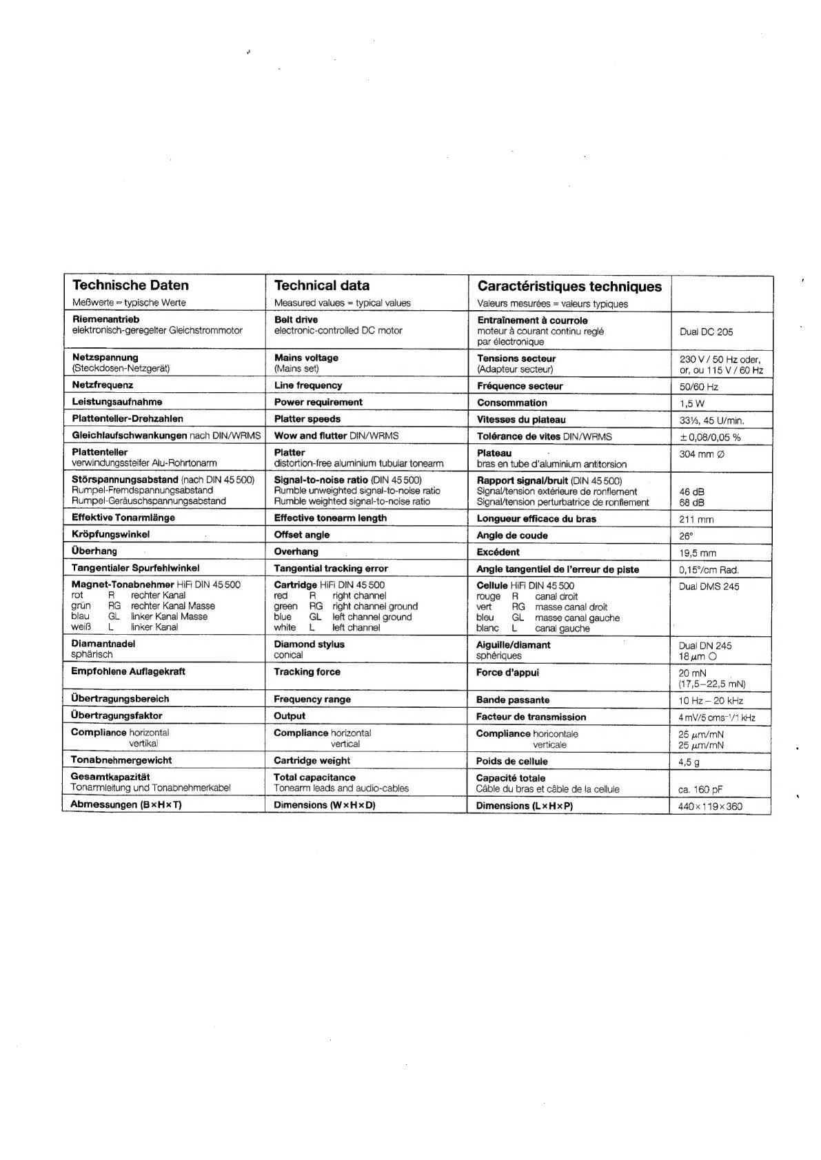
repeat
Sie
durch
seitlichen
Druck
die
beiden
Transportsicherungen
11
(Fig.
1).
—
Plattenteller
aufsetzen
und
die
in
der
Mitte
des
Plattentellers
ange-
brachte
Sicherung
nach
unten
driicken,
bis
sie
in
die
Rille
der
Plattentellerachse
einrastet
(Fig.
2).
Plattentellerbelag
auflegen.
-
ea
2
in
die
dafiir
vorgesehenen
Aussparungen
einstecken
ig.
3).
-
Schieben
Sie
die
Abdeckhaube
1
parallel
zu
der
Stellung
der
Scharniere
2
(Offnungswinkel
ca.
60°)
satt
in
diese
ein.
In
dieser
Stellung
!aBt
sich
die
Andeckhaube
jederzeit
wieder
abnehmen.
AnschliuB
des
Netzgerates
Das
mitgelieferte
Netzgerat
wird
an
die
AnschluBbuchse
14
ange-
schiossen.
Primarseitig
ist
das
Netzgerat
entsprechend
der
Span-
nungsangabe
auf
dem
Typenschild
entweder
in
eine
Netzsteckdose
mit
230
V
/
50
Hz
oder
115
V
/
60
Hz
einzustecken.
AnschiuB
an
den
Verstarker
—
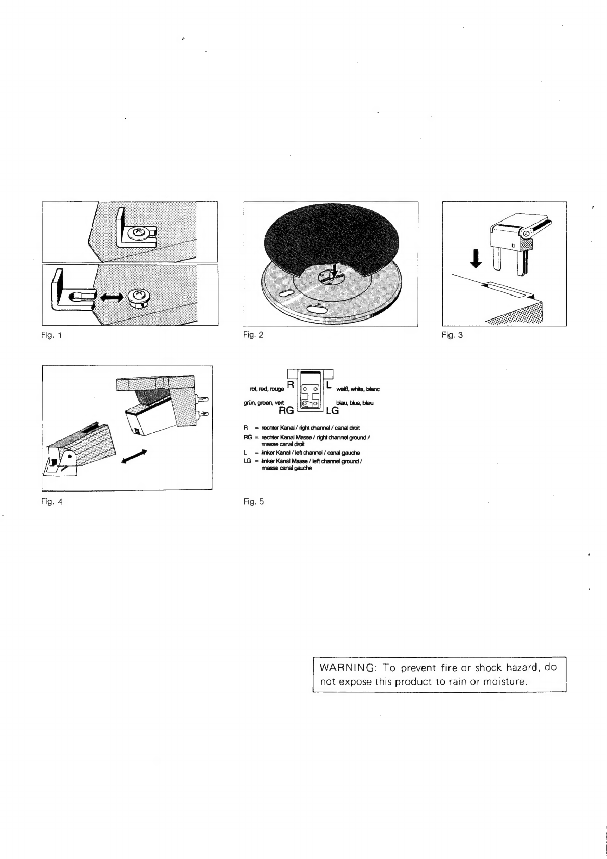
Verbinden
Sie
das
mit
RCA-(Cinch-)Steckern
ausgerlstete
Tonab-
nehmerkabel
12
mit
dem
Phono-Magnet-Eingang
des
Verstarkers
(rot
=
rechter
Kanal,
wei
=
linker
Kanal).
~
Den
Masseanschlu8
13
an
die
Masseschraube
des
Verstarkers
anschlieBen.
Tonarm
ausbalancieren,
Auflage-
und
Antiskatingkraft
einstellen
1.
Antiskating-Einrichtung
5
entgegen
dem
Uhrzeigersinn
bis
an
Anschlag
drehen.
2.
Tonarm-Balancegewicht
3
auf
den
Tonarm
drehen.
Tonarm
entriegeln
und
Uber
die
Tonarmablage
nach
innen
schwen-
ken.
Lifthebel
6
in
Stellung
Z
bringen.
Dabei
Tonarm
festhalten.
3.
Tonarm
durch
Drehen
des
Balancegewichts
exakt
ausbalancieren.
Der
Tonarm
ist
exakt
ausbalanciert,
wenn
er
frei
schwebt.
4.
Tonarm
auf
die
Tonarmstiitze
zurlickfiihren
und
verriegeln.
Tonarm-Balancegewicht
3
festhalten
und
das
vordere
Rad
mit
der
Skalenteilung
4
auf
0"
drehen
(,0“
steht
Uber
der
Markierung
in
Tonarmrohr).
Jetzt
das
komplette
Tonarm-Balancegewicht
entgegen
dem
Uhrzei-
gersinn
verdrehen
und
erforderliche
Auflagekraft
einstellen.
Auflage-
kraft
fir
das
eingebaute
Tonabnehmersystem
DMS
245
=
20
mN.
An
der
Antiskatingeinrichtung
5
stellen
Sie
den
dazugehérigen
Wert
nach
folgender
Tabelle
ein:
Auflagekraft
Antiskating-Einstellung
5
Auflagekraftskala
4
1
=
10mN
1
1,5
=
15mN
1,5
DMS
245-2
=
20mN
2
2,5
=
25mN
2,5
Start,
Tonarmlift
—
Wahlen
Sie
mit
dem
Schalter
8
die
Plattentellerdrehzahl
33
oder
45
U/min,
schwenken
Sie
den
Nadelschutz
nach
vorne
und
bringen
Sie
den
Lifthebel
6
in
Steliung
¥.
—
Nehmen
Sie
den
Tonarm
von
der
Tonarmsttitze
und
schwenken
Sie
ihn
Uber
die
Einlaufrille
der
Schallplatte.
Der
Tonarm
wird
jetzt
mit
dem
Lifthebel
6
bed&ft
und
plattenschonend
abgesenkt
Z.
—
Mit
dem
Lifthebel
kann
der
Tonarm
an
jeder
beliebigen
Stelle
—
auch
zur
kurzzeitigen
Spielunterbrechung
—
abgehoben
werden
(Lifthebel
in
Stellung
©).
Der
Plattenteller
dreht
sich
weiter.
Stop
Am
Ende
der
Schallplatte
wird
der
Tonarm
automatisch
zur
Tonarm-
stiitze
zurtickgeflihrt
und
das
Gerat
abgeschaltet.
;
—
Sie
kénnen
den
Plattenspieler
auch
abschalten,
indem
Sie
den
Lifthebel
6
in
Stellung
¥
bringen
und den
Tonarm
auf
die
Tonarm-
stiitze
zuriickfihren.