Die
Bedienung
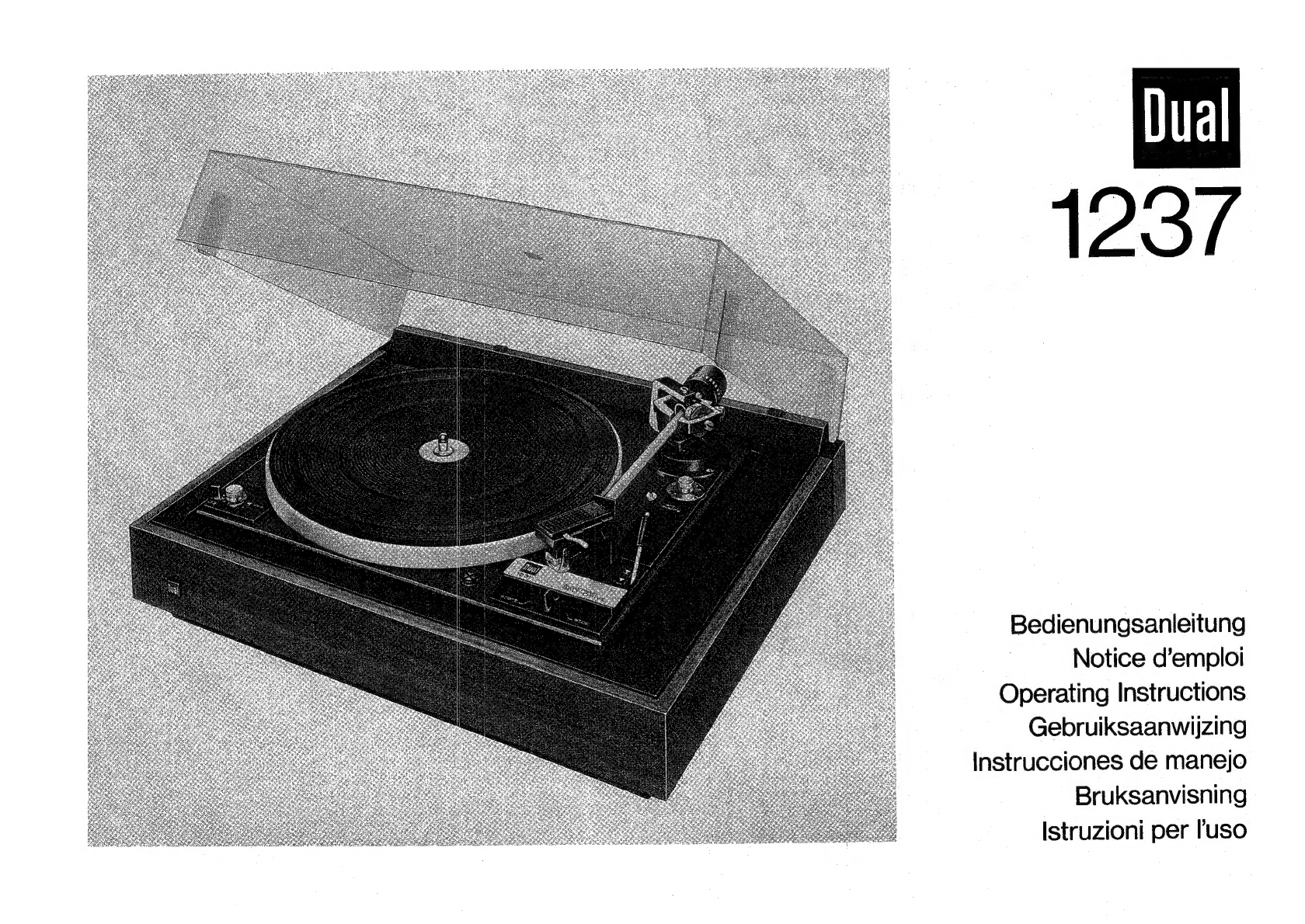
(1)
Plattenteller-DrehzahI-Einstellung
(2)
Tonhéhen-Abstimmung
(3)
Mitlaufachse
fiir
Einzelspiel
(4)
Tonarmgriff,
Tonabnehmerkopf-Verriegelung
(5)
Tonabnehmerkopf
(Systemtrager)
(6)
Tonarmstitze
(7)
Tonarmverriegelung
(8)
Justierschraube
fiir
Tonarmilift
(9)
Tonarmauflagekraft-Einstellung
(10)
Tonarm-Balancegewicht
(11)
Feststellschraube
fiir
Tonarm-
Balancegewicht
(12)
Antiskating-Einstellung
(13)
Tonarmlift
(14)
Justierschraube
fiir
Tonarmauf-
setzpunkt
(unter
der
Zierleiste)
(15)
Steuertaste
fir
“start”
und
“stop”
(17)
Transportsicherungsschraube
(18)
Wechselachse
AW
3
(19)
Zentrierstiick
fiir
17
crm-Schall-
platten
(20)
Abwurfsdule
AS
12
fiir
17
cm-
Schallplatten
(SonderzubehGr)
Commandes
de
l'appareil
(1)
Réglage
de
la
vitesse
(2)
Réglage
de
la
hauteur
du
son
(3)
Axe
pour
un
seul
disque
(4)
Poignée
du
bras
Verrouillage
de
la
téte
de
lecture
(5)
Cellule
(porte
-
cellule)
(6)
Support
du
bras
(7)
Verrouillage
du
bras
(8)
Vis
de
réglage
du
lift
du
bras
(9)
Réglage
de
la
force
d’appui
(10)
Contrepoids
(11)
Vis
de
blocage
pour
le
contre-
poids
oh
(12)
Réglage
de
l’antiskating
(13)
Léve-bras
(14)
Vis
de
réglage
de
point
de
pose
du
bras
(sous
la
réglette
décorative)
(15)
Touche
de
commande
pour
start”
et
,,stop”’
(17)
Vis
de
sécurité
pour
le
transport
(18)
Axe
changeur
AW
3
(19)
Centreur
pour
disques
45
t/min
(20)
Axe
changeur
AS
12
pour
disques
45
t/min
(accessoire
spécial)
.
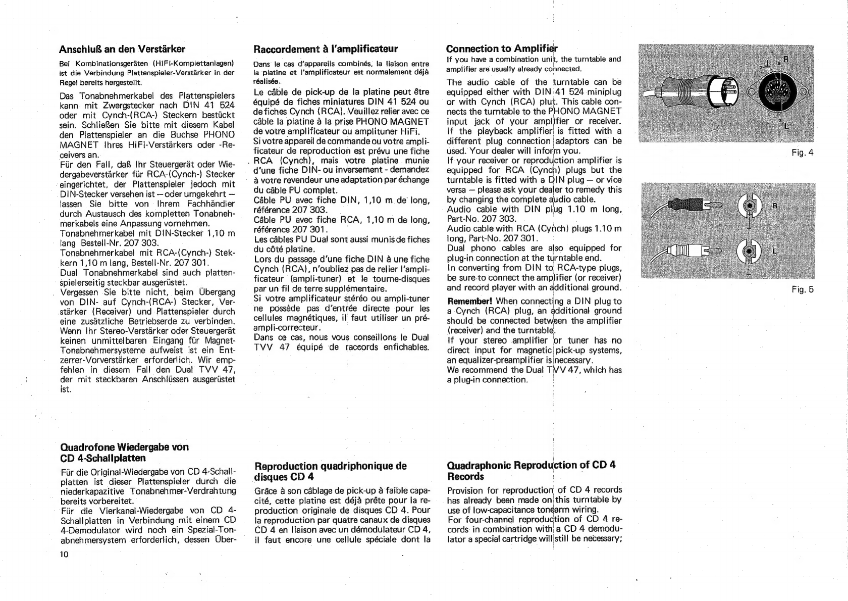
Operating
(1)
Speed-selector
(2)
Pitch
control
(3)
Single-play
spindle
|
(4)
Tonearm
lift
and
cartridge
holder
tock
(5)
Cartridge
holder
(6)
Tonearm
support
(7)
Tonearm
lock
(8)
Cue
control
height
adjustment
(9)
Stylus
force
setting
|
(10)
Tonearm
counterweight
(11)
Set
screw
for
tonearm
counterbalance
(12)
Anti-skating
setting,
(13)
Cue
control
(14)
Adjustment
screw
for
tonearm
set-down
(below
decorating
strip)
(15)
Automatic
start
-
stop
switch
(17)
Transport
safety
(hold
down)
screw
(18)
Multiple-play
spindle
AW
3
(19)
Adapter
for
large-hole
records
(20)
Multiple-play
spindle
AS
12
for
lJarge-hole
records
(special
acces-
sory)
|