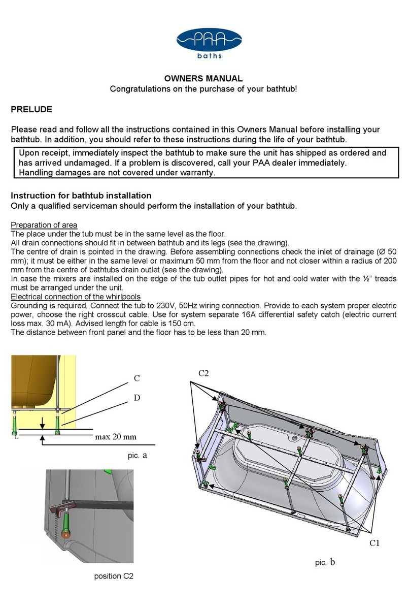
Pre-installation data sheet Duravit No. 1_22.03.1
Pre-installation
INSTALLATION LOCATION / INSTALLATION ROOM
> Make sure that the installation location fulfils the following criteria
Doors / external
access
• Ensure that doors or other access openings are
large enough to accommodate transport dimen-
sions, keeping in mind the weight and need for
sufficient manoeuvring room.
Required area • Allow for enough space around the tub for the in-
stallation.
Floor • Completely level.
• At a right angle to the wall.
• Note the overall strength of the floor structure
including the floor finish.
• There must not be any underfloor heating under
the tub.
• Install tubs after the tiles. (Top edge of finished
floor).
• Depending on the combination of tub and whirl
system it is possible that system components may
protrude beyond the edge of the tub. We there-
fore recommend installation in a support frame.
• Tolerances for acrylic: As a result of the manu-
facturing process, deviations from the nominal
dimensions may occur within the limits specified
in the DIN 198 standard. Please take this into
account in your planning.
Wall • Tiled.
• At a right angle to the tub.
• Completely straight.
• Note the overall strength of the wall structure
including the wall finish.
WATER INSTALLATION
NOTE
Bathtubs without overflow will overflow into the room.
> If a bathtub is installed without an overflow, a floor drain must be
installed to protect the building against overflow water in accordance
with DIN 1986-100.
NOTE
A pipe interrupter is absolutely essential for tubs with a base inlet (DIN
EN 1717).
> Comply with assembly scheme.
Seitenansicht
Lateral view
150
>
=
Gezeichnet
Drafted
Ge ndert
Modified
Gepr ft
Certified
Datum
Date Name Ma§stab
Scale
Name
Bezeichnung
Description
Artikel-Nr.
Model-No.
Technische Verbesserungen und optischeVernderungen an den abgebildeten Produkten behalten wir uns vor.
We reserve the right to make technical improvements and enhance the appearance of the products shown.
1:20
1:10
1:5
X
# W-T-
Allgaier
000000 - 00 - 0
08.10.13
000000
Schematische Zeichnung mit Rohrunterbrecher
Zeichnung
Drawing
Spezial Ab-und berlaufgarnitur mit Bodenzulauf
fr Badewanne
Special waste and overflow with base inlet
for bathtubs
WLT
08.10.13
Water connection
• Connections for the water supply and drains must be in compliance
with the currently valid standards and public regulations.
• Position the water drain (DN 50) flush to the mounting surface or out of
the wall directly above the mounting surface; see drawing for recom-
mended area.
MAINTENANCE OPENINGS AND AIR SUPPLY
NOTE
It is recommended to install the tub with a removable bathtub panel due
to the improved maintenance options.
Tiling the tub
The following maintenance openings must be provided:
• Cable-driven waste and overflow 200 x 200 mm
• Units 500 x 500 mm
(Please see the section on “Maintenance openings”)
• Provide an opening in the panel for the air supply with an effective area
of approx. 15 cm2(e.g. 3 x 5cm or 2 x 7.5cm).
Tub with a panel
• The panel must be removed for maintenance, and with a seamless pan-
el, the tub must be removed from the wall. Your plans should therefore
include a clearance in front of the tub.
• The air supply for the whirl system (ventilation grille/ventilation slot)
must not be covered.
ELECTRICAL INSTALLATION
DANGER Risk of fatal electric shock
> Disconnect the power supply while working on the electrical
components.
> The device must be earthed. Earthed appliances must be permanently
connected to fixed wiring.
> Connect the device only to the designated electrical cable.
> NEVER touch the power supply line with wet hands.
Pre-installation
> Lay a permanent power supply line which must be on a separate
circuit.
• The device itself does not have electrical leakage protection func-
tion. The device must be supplied through a residual current device
(RCD) with a rated residual operating current not exceeding 30 mA.
• Means for disconnection must be incorporated in the fixed wiring
in accordance with the wiring rules and have a contact separation
in all poles that provides full disconnection under overvoltage cat-
egory III conditions outside the prescribed protection zones (0 – 2).
• Leave 3000 mm of the supply line exposed.
> Lay an equipotential bonding cable:
• Leave 3000 mm of cable exposed.
> Select a supply line cross-section based on the connected load on the
identification plate (2.5 mm – 4 mm).
> Confirm that the grounding wire is 10 mm (⅜ ”) longer than the L and
N wire.
> Install a circuit breaker.
3
