manuals.online logo
Brands
  1. Home
  2. •
  3. Brands
  4. •
  5. E2S
  6. •
  7. Marine Equipment
  8. •
  9. E2S BExA120D User manual

E2S BExA120D User manual

__________________________________________________________________________________________________________________________________
EuropeanSafetySystemsLtd. Impress House, MansellRoad, Acton, LondonW37QHsales@e2s.com Tel:+44 (0)2087438880
www.e2s.com Fax:+44 (0)2087404200
DocumentNo. IS2425-PIssueB17-04-02Sheet1of4
INSTRUCTION MANUAL(ATEX)
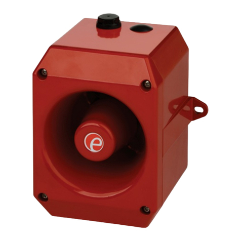
BExA120DandBExA110D
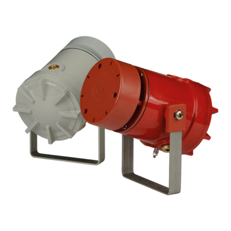
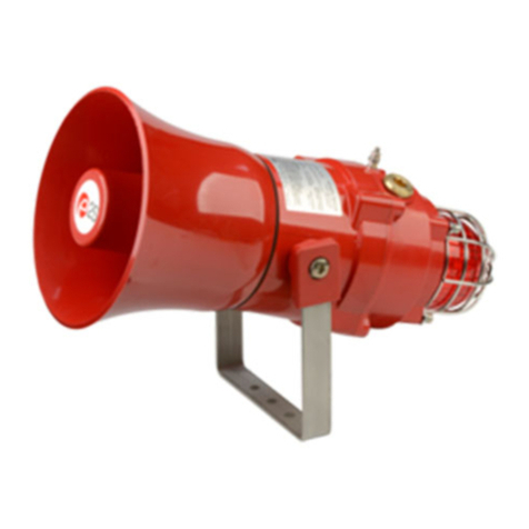
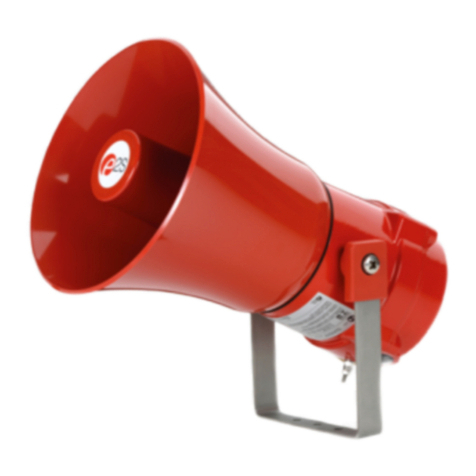
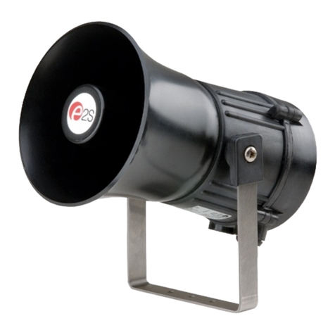
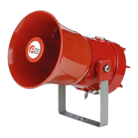
FlameproofAppello Speech Sounder
s
1)Introduction
TheBExA120DandBExA110Daresecondgeneration
flameproof AppelloSpeech Sounders whichare certified to the
European StandardsEN50014:1992andEN50018:1994
andmeet therequirementsof theATEXdirective94/9/EC. The
units,whichhaveafacility to recordamessage ofupto16
secondsin duration,can be used in hazardousareaswhere
potentially flammable atmospheresmaybe present.The
speechmessagecanbeprecededby oneofninedifferent
alarmtones(seetonetableon Page 4). The BExA120D unit
producesoutputlevels in the112dB(A) rangeandthe
BExA110D unit produces output levels in the 110dB(A) range.
Both sounders can beusedinZone 1and Zone 2 areaswith
gasesin groups IIA,IIBandIIC and temperature
ClassificationsofT1,T2,T3andT4.
2)Marking
Allunitshavearating label, whichcarriesthe following
important information:-
UnitType No. BExA120DorBExA110D
Input Voltage: DC Units 24V
AC Units 230V or 115V
Code: EExdIICT4(Tamb. –50to+55°C)
CertificateNo. KEMA99ATEX6312
Warnings:DONOTOPENWHENANEXPLOSIVE
GASATMOSPHEREISPRESENT
COVERBOLTSCLASS A4-80
USEHEATRESISTINGCABLES ANDCABLEGLANDS
(Rated 95ºC)ATAMB.TEMPERATURES OVER40ºC
Year of Construction/
Serial No.i.e. 02 / 1A22000001
3) TypeApprovalStandards
The Appello's have an ECType examination certificate issued
byKEMAandhavebeenapproved tothefollowingstandards:-
EN50014: 1992 +prA1 General Requirements
EN50018: 1994 +prA1 Flameproof Enclosure‘d’
4) InstallationRequirements
The unitsmust beinstalledin accordancewith thelatest issues
oftherelevant parts ofthe BSEN60079 specifications orthe
equivalent IEC specifications –Selection, Installationand
maintenanceof electrical apparatusforuse in potentially
explosiveatmospheres(other thanminingapplicationsor
explosiveprocessing andmanufacture):-
BS EN60079-14 : 1997 ElectricalInstallationsinHazardous
Areas(otherthan mines)
BS EN60079-10 : 1996 Classificationof HazardousAreas
The installationof theunitsmustalsobe in accordance with
anylocal codesthat may apply and should onlybe carried out
byacompetentelectricalengineerwhohasthenecessary
training.
5) Zones,GasGroup,Categoryand Temperature
Classification
The BExA120D and BExA110DAppello’s have been certified
EEx d IIC T4 (Tamb.–50 to +55ºC). Thismeans thatthe units
canbe installed in locationswith thefollowingconditions:-
AreaClassification:
Zone 1 Explosivegasair mixturelikely tooccurin
normal operation.
Zone 2 Explosivegasair mixturenot likely to occur,
andifit does, it will only existfor ashort time.
GasGroupings:
GroupIIA Propane
GroupIIB Ethylene
GroupIIC Hydrogen andAcetylene
EquipmentCategory: 2G
TemperatureClassification:
T1 400oC
T2 300oC
T3 200oC
T4 135oC
Ambient Temperature Range:
-50°C to+55°C
6) LocationandMounting
The locationof the Appello Speech Sounders should be made
withdue regardto thearea overwhich therecorded messages
must be audible.The Appello'sshouldonly be fixedtoservices
that cancarry the weight ofthe unit.
0344
Epsilonx:
GasGroupand
Category:
CE Marking:
NotifiedBody No.
II2G
__________________________________________________________________________________________________________________________________
EuropeanSafetySystemsLtd. Impress House, MansellRoad, Acton, LondonW37QHsales@e2s.com Tel:+44 (0)2087438880
www.e2s.com Fax:+44 (0)2087404200
DocumentNo. IS2425-PIssueB17-04-02Sheet2of4
The units shouldbesecurely bolted toasuitablesurface using
the 7mm diameterboltholesin thestainlesssteelUshaped
mountingbracket(seefigure1). The angle canthen be
adjusted in the directionthat the messageisprimarily required
tocover. Thiscan beachievedbyloosening the two large
bracketscrews in theside of the unit,which allowadjustment
in steps of 18°. Oncompletion of the installation the two large
bracketadjustment screwsontheside of the unit mustbe fully
tightenedto ensurethat theunit cannot moveinservice.
7) SafetyWarning (ElectrostaticHazard)
The acoustic horn sectionis made of ABSPlastic,thereforeto
avoidapossibleELECTROSTACTIC CHARGEthe unitmust
only be cleanedwith a damp cloth.
8) Access totheFlameproofEnclosure
In order to connecttheelectrical supplycablesandto recorda
messageontotheunits,itisnecessary toremovethe
flameproof cover togain accessto theflameproof chamber. To
achieve this removethe four M6 hexagonsocket head screws
(seefigure 2)and withdrawtheflameproofcovertaking
extremecarenottodamagetheflameproofjointsin the
process.
Notethefour M6screwsareClassA4-80stainlesssteel
andonlyscrewsof thiscategorycanbeused on these
units. Itis thereforeimportant thatthesescrews and their
springwashersarekept in a safe place duringinstallation.
Oncompletionofthecable wiringinstallationtheflameproof
jointsshouldbe inspectedto ensurethat theyarecleanand
thatthey havenotbeen damagedduringinstallation.Also
checkthat theearthbondingwirebetweenthetwocasting
sectionsissecureandthe‘O’ringseal isinplace.When
replacingtheflameproof cover casting ensurethat itis square
withthe flameproof chamber castingbefore inserting. Carefully
pushthecoverin placeallowing time fortheairto beexpelled.
Only afterthecover isfullyin placeshould the four M6
Stainless SteelA4-80 coverbolts and theirspringwashers be
insertedand tighteneddown. If the coverjams while it is being
inserted, carefully remove it andtryagain.Never use the cover
boltsto forcethe cover intoposition.
9) PowerSupplySelection
Itis important that asuitable powersupplyisused torunthe
Appello’sandthat thecables usedto connecttheunits tothe
powersupply areselectedtoensurethat theyhavethe
necessary capacity.
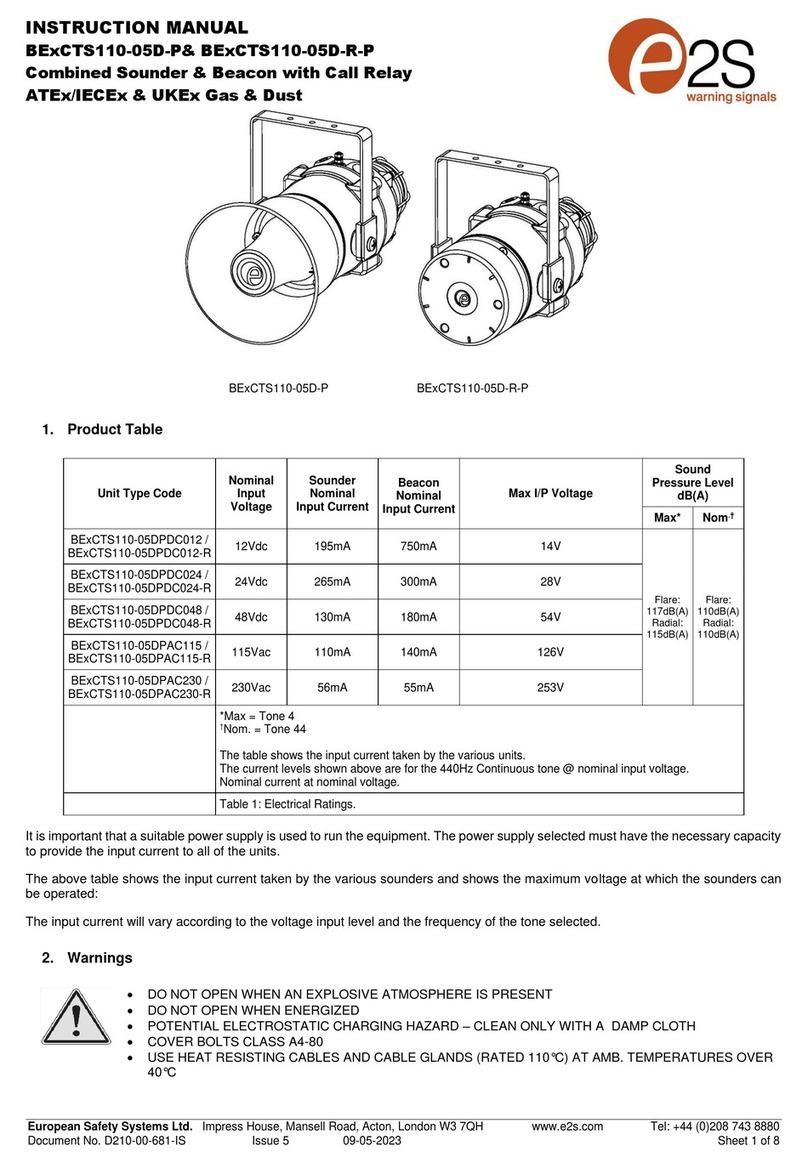
The followingtableshowstheinputcurrent taken by the
various sounderunits:-
UnitTypeInputInputMax.
VoltageCurrentI/PVolts
BExA120D24VDC 480mA30V
BExA120D230VAC45mA253V
BExA120D115VAC90mA126V
BExA110D24VDC 480mA30V
BExA110D230VAC45mA253V
BExA110D115VAC90mA126V
The input currentwillvaryaccordingtothe voltage inputlevel
and the frequencyofthe toneselected.Thecurrent values
shown abovearefor the554/440Hz tone @nominalinput
voltage. The above tablealso shows the maximum voltages at
which theunitscan beoperated.
10) CableSelection
Whenselecting the cable size consideration mustbegivento
the inputcurrentthat each unitdraws (seetableabove), the
numberofunits onthelineandthelengthofthecableruns.
The cablesizeselected musthavethe necessary capacity to
providetheinputcurrenttoalloftheAppello’s connected to
the line.
SAFETY WARNING: If the Appello’s are used athigh ambient
temperatures,i.e.over +40ºC, thenthecableentry
temperature mayexceed +70ºCand thereforesuitable heat
resisting cables mustbeused,witharatedservice
temperature of at least 95ºC.
11) Earthing
Both AC andDCAppellounitsmustbeconnectedto agood
qualityearth. The units are provided with internal and external
Figure 1
Flameproof
Chamber
Flameproof
Cover
S/SMounting
Bracket
Figure2
4off M6CoverScrews
ExternalEarth
Terminal
PlasticAcousticHorn
Pleasesee SafetyWarning
inSection 7of thismanual
__________________________________________________________________________________________________________________________________
EuropeanSafetySystemsLtd. Impress House, MansellRoad, Acton, LondonW37QHsales@e2s.com Tel:+44 (0)2087438880
www.e2s.com Fax:+44 (0)2087404200
DocumentNo. IS2425-PIssueB17-04-02Sheet3of4
earthing terminalswhichare bothlocated ontheflameproof
coversection oftheunit (seefigures2and3).
When using theexternal earthterminala cablecrimp lug must
be used. Thecablelugshouldbe locatedbetween thetwoM5
stainlesssteelflat washers. TheM5stainlesssteel spring
washermust be fixed betweenthe outer flat washerandthe
M5 stainlesssteel nut toensurethat thecablelugissecured
againstlooseningandtwisting.
Theinternalearthbondingwireensures that agoodquality
earth is maintained betweentheflameproofchambercasting
andthe flameproofcovercasting.
12) CableGlands
TheBExA120Dand BExA110D Appellounitshave dualcable
glandentrieswhich haveanM20 x1.5entrythreadasstandard
oraPG13.5thread asaspecial. Onlycableglandsapproved
forEx‘d’applications canbe used, whichmustbe suitable for
the typeof cable beingusedand alsomeettherequirements
of theEx ‘d’ flameproof installationstandard BSEN60079-14:
1997.
SAFETY WARNING: If the Appello’s are used athigh ambient
temperatures,i.e.over +40ºC, thenthe cableentry
temperature mayexceed +70ºCand thereforesuitable heat
resistingcableglands mustbeused, with aratedservice
temperature of at least 95ºC.
Ifahigh IP (Ingress Protection)ratingisrequired thena
suitable sealingwasher mustbe fitted under the cablegland.
Whenonly one cable entry isusedtheother onemustbe
closed with an Ex ‘d’ flameproofblankingplug,which mustbe
suitablyapprovedfortheinstallation requirements.
13) CableConnections
Beforethe Appello isinstalled in ahazardousarea,the
required messageto be broadcast shouldbe recorded onthe
units, see section 14 ofthisinstructionmanual.
The cableconnectionsaremadeinto theterminal blockson
the electronicpcbassembly located in theflameproof
enclosure.Seesection8ofthis manual foraccesstothe
flameproofenclosure. On theACunitsathree-way fused
terminalblockis providedfor the live and neutralmains supply
lines(seefigure 5).Togainaccesstothe terminal block,
remove the terminal cover byunscrewingthenylonnut.The
earth terminal inthe centerofthe three-wayterminal blockis
providedfor usewhenamessage isbeingrecorded, see
section14ofthisinstruction manual. Theinternal earth
terminal in thecovershouldbe usedwhen installingtheunit.
Onthe DC units atwo-way terminal blockis provided for+ve
and –ve supply lines (seefigure4).
A singlewire withacross sectionalarea of up to 4mm² can be
connectedto eachterminal way or ifaninput andoutputwire
isrequired two 2.5mm²wires can be connectedtoeach
terminalway onDCunitsandtwo1.5mm²wirescanbe
connected toeach terminal way on AC units.When connecting
wires to theterminals great care should betaken to dressthe
wiresothatwhen thecoveris insertedintothechamberthe
wires donotexert excesspressure on theterminal blocks. This
isparticularly important whenusingcables with large cross
sectional areassuchas2.5mm² andabove.
2off M20
CableEntries
InternalEarthTerminal
Figure3
InternalBonding
WireTerminal
Figure 5
VolumeControl
Tone andRecord
Headers
Microphone
PushSwitchLED
BExA120D and BExA110DAC Appello
LEN
Terminal Cover
ACTerminals
Figure 4
BExA120D andBExA110D DCAppello
VolumeControl
DCTerminals
Tone andRe
cord
Headers
Microphone
PushSwitch
LED
+
-
A
B
C
R
__________________________________________________________________________________________________________________________________
EuropeanSafetySystemsLtd. Impress House, MansellRoad, Acton, LondonW37QHsales@e2s.com Tel:+44 (0)2087438880
www.e2s.com Fax:+44 (0)2087404200
DocumentNo. IS2425-PIssueB17-04-02Sheet4of4
14) Recording aMessage
Beforeinstalling the Appello unitsinahazardous area the
messagerequiredtobebroadcast mustberecordedontothe
unit. Asinglemessageofup to16 secondscanbe recorded
oneach Appellounit. Themessagemustberecorded while
the unitisstill ina safe area.
TorecordamessagetheAppellomustbeconnected toan
input supplyvoltageappropriatetotheunitbeing used,i.e.
24Vfor DC unitsandeither 230V or 115VforAC units
dependingon theunitvoltage.
1)Set the unittotherecordmode byshortingout the
recordheaderpinsmarkedR,(seefigure4).
2)Switchon thepowersupply to theunit.
3)Pressandholdthe PushSwitchwhile speakinginto
the microphonetorecordamessageof up to16
seconds in duration. NOTE IFTHE LED INDICATOR
GOESOUTBEFORETHEENDOFTHE
RECORDING,THE MESSAGE LENGTHHAS BEEN
EXCEEDED ANDWILL NEEDTOBE RECORDED
AGAIN.
4)Releasethe push switchat the end of themessage.
5)Switchoffthepower supply.
6)Removethe pin headerfrom therecord pinsR.
7)Checkthat themessage hasrecorded correctly by
switchingon thepowersupply and the message
shouldplayback.
15) ToneSelection
Themessagecan be precededbyone ofnineselectable tones
orby a silence period of0.5seconds.
Toselecttherequired toneorthesilence periodtheheader
pinsA B andC(seefigure4) should bepatched asperthe
tonetableon thispage.
TONESELECTIONTABLE
ToneNo. ToneDescription
16) End ofLineMonitoring (DC Units)
OnBExA120DandBExA110DDCAppellounits,dcreverse
line monitoringcan beused ifrequired.All DCunitshavea
blocking diode fitted in their supplyinput lines.Anendofline
monitoringdiode oran endofline monitoringresistorcan be
connectedacross the +ve and –ve terminals.Ifan end ofline
resistorisused it musthave aminimumresistancevalueof
3k3 ohmsandaminimum wattageof 0.5watts oraminimum
resistancevalue of 500 ohmsandaminimum wattageof2
watts.
17) VolumeControl
All BExA120D andBExA110DAppellounitshaveavolume
controlto adjust theoutput level.Tosetthe required output
leveladjust the potentiometeronthepcb. For maximum output
levelthepotentiometershouldbe set to thefully clockwise
position.
SAFETYNOTE
To maintainsafety when recording a message on AC Appello
units, an earthwiremustbe connected totheearth terminal on
the three-way terminal block andtheTerminal Covermust be
replacedbefore thesupply to theunit is switchedon(see
figure5).
1
Alternating 800/1000Hz @2Hz.
4cycles
2
SlowWh
oop500/1200Hz @
0.3Hz with0.5gap.
2cycles
3
Sawtooth 1200/500Hz @1Hz
4cycles
4
Alternating 544/440Hz @
100/400mS intervals.
4cycles
5
Continuous @1000Hz
2seconds
6
Simulated Bell sound
2seconds
7
AustralianAlert420Hz with
0.625secintervals.
4cycles
8
Intermittent 100
0Hz@0.5Hz
3cycles
9
AustralianEvacuate500/1200Hz
3.75sec. ON-0.25secOFF
2cycles
10
Silence0.5sec gap
RCBA
RCBA
RCBA
RCBA
RCBA
RCBA
RCBA
RCBA
RCBA
RCBA

This manual suits for next models

1

Other E2S Marine Equipment manuals

E2S BExDCTS110-05D User manual

E2S

E2S BExDCTS110-05D User manual

E2S A100 AlertAlarm User manual

E2S

E2S A100 AlertAlarm User manual

E2S D2xB1LD2 User manual

E2S

E2S D2xB1LD2 User manual

E2S STExC1 User manual

E2S

E2S STExC1 User manual

E2S D1xS1 Series User manual

E2S

E2S D1xS1 Series User manual

E2S BExCS110-L1 User manual

E2S

E2S BExCS110-L1 User manual

E2S DL105H AlertAlight User manual

E2S

E2S DL105H AlertAlight User manual

E2S STExS1 User manual

E2S

E2S STExS1 User manual

E2S BExS110D-SIL User manual

E2S

E2S BExS110D-SIL User manual

E2S BExS110D User manual

E2S

E2S BExS110D User manual

E2S BExH120DDC024 User manual

E2S

E2S BExH120DDC024 User manual

E2S IS-A105N User manual

E2S

E2S IS-A105N User manual

E2S AL121H Series User manual

E2S

E2S AL121H Series User manual

E2S STExS1 User manual

E2S

E2S STExS1 User manual

E2S A112N User manual

E2S

E2S A112N User manual

E2S E2xS1RDC024 Manual

E2S

E2S E2xS1RDC024 Manual

E2S IS-mA1M User manual

E2S

E2S IS-mA1M User manual

E2S AlertAlight AL112NXDC012 User manual

E2S

E2S AlertAlight AL112NXDC012 User manual

E2S BExCS110-05D-P User manual

E2S

E2S BExCS110-05D-P User manual

E2S DL112H User manual

E2S

E2S DL112H User manual

E2S E2xS121EG Troubleshooting guide

E2S

E2S E2xS121EG Troubleshooting guide

E2S Sontel BExTS110DAC115 User manual

E2S

E2S Sontel BExTS110DAC115 User manual

E2S A105N APPELLO User manual

E2S

E2S A105N APPELLO User manual

E2S IS-AL105NL User manual

E2S

E2S IS-AL105NL User manual

Popular Marine Equipment manuals by other brands

Furuno 1824C-BB installation manual

Furuno

Furuno 1824C-BB installation manual

SurTec Star-vox 22PSER001 manual

SurTec

SurTec Star-vox 22PSER001 manual

Sealite TRIDENT-3000 Installation & service manual

Sealite

Sealite TRIDENT-3000 Installation & service manual

AIS DNVMR10ID3S-M2-5RT user guide

AIS

AIS DNVMR10ID3S-M2-5RT user guide

Trenz PILOT PLUG quick start guide

Trenz

Trenz PILOT PLUG quick start guide

CORRECT CRAFT LINC PANORAY owner's manual

CORRECT CRAFT

CORRECT CRAFT LINC PANORAY owner's manual

Fusion Apollo RA770 installation instructions

Fusion

Fusion Apollo RA770 installation instructions

Reson SeaBat 8160 Operator's manual

Reson

Reson SeaBat 8160 Operator's manual

FLEXPRIN APOLLO-6 user manual

FLEXPRIN

FLEXPRIN APOLLO-6 user manual

Kongsberg EM 710 installation manual

Kongsberg

Kongsberg EM 710 installation manual

SmartCell SC-31-0100-0001-99 installation guide

SmartCell

SmartCell SC-31-0100-0001-99 installation guide

Raymarine autopilot Owner's handbook

Raymarine

Raymarine autopilot Owner's handbook

Apollo Discovery Open Area Voice Sounder installation guide

Apollo

Apollo Discovery Open Area Voice Sounder installation guide

EPAK DivKit VSAT Ri Series manual

EPAK

EPAK DivKit VSAT Ri Series manual

Hatteland HD 15T22 MMD-xxx-F series user manual

Hatteland

Hatteland HD 15T22 MMD-xxx-F series user manual

Yacht Sentinel YS user guide

Yacht Sentinel

Yacht Sentinel YS user guide

Kongsberg Simrad ES80 instruction manual

Kongsberg

Kongsberg Simrad ES80 instruction manual

JRC jue-87 instruction manual

JRC

JRC jue-87 instruction manual

manuals.online logo
manuals.online logoBrands
  • About & Mission
  • Contact us
  • Privacy Policy
  • Terms and Conditions

Copyright 2025 Manuals.Online. All Rights Reserved.