E2S IS-mA1M User manual

_______________________________________________________________________________________________________________________________
European Safety Systems Ltd. Impress House, Mansell Road, Acton, London W3 7QH www.e2s.com Tel: +44 (0)20 8743 8880
Document No. D251-00-051-IS Issue 1 12-08-2022 Sheet 1 of 6
INSTRUCTION MANUAL (ATEX)
IS-mA1M Minialarm
Intrinsically Safe Round Sounder
1) Introduction
The IS-mA1M minialarm is an ATEX and IECEx certified
intrinsically safe sounder which produces a loud warning
signal in a hazardous area. Forty-nine first stage alarm
sounds can be selected by internal switches and each one
can be externally changed to a second or third stage alarm
sound. The sounder is Category M1 equipment for mining
and is designed such that it can stay operational when an
explosive atmosphere is present.
2) Description
Fig 1 shows a simplified block diagram of an IS-mA1M
minialarm sounder. The device operates immediately power
is applied to the + and – terminals which are duplicated to
allow a second sounder to be connected in parallel, or for an
end of line monitoring resistor to be installed. The output tone
is defined by the positions of the six internal switches and this
tone can be changed to a second or third stage alarm tone by
connecting terminals S2 or S3 to 0V. The tone generator is
crystal controlled to ensure that when two sounders
connected to the same power supply are started at the same
time the output tones remain synchronised.
3) Supply Voltage
The IS-mA1M minialarm sounder has been designed to
operate in a hazardous area from a 24V dc supply via a 28V
93mA resistive ATEX and IECEx certified Zener Barrier or
Galvanic isolator. The sounders may be tested or used in
safe areas without a Zener Barrier or Galvanic Isolator, but at
supply voltages above 16V the internal current limit will
function and therefore it is recommended that they are not
operated continuously with a direct supply greater than 16V.
IS-mA1M Sounder
Tone Generator
Tone Selection Switches
Volume Control
_
_
S2
S3
+
+
Fig 1 Simplified block diagram
4) Intrinsic Safety Certification
4.1 ATEX certificate
The IS-mA1M minialarm sounder complies with the following
standards:-
EN IEC 60079-0:2018
EN60079-11:2012
EN60079-26:2014 Ed 3.0
The EC-Type Examination Certificate SIRA 05ATEX2084X
has been issued by the Notified Body Sira. This confirms
compliance with the European ATEX Directive 2014/34/EU
for Group I, Category M1 equipment. The sounder carries
the Community Mark and subject to local codes of practice,
may be installed in any of the EEA member countries. When
designing systems for installation outside the UK, the local
Code of Practice should be consulted.
1) The certification marking is as follows:
2) The equipment may only be used in atmospheres
endangered by fire damp and / or coal dust. The
equipment is intended to remain functional in such
atmospheres.
3) The equipment is only certified for use in ambient
temperatures in the range -40oC to +60oC and
should not be used outside this range.
4) The certificate number has an ‘X’ suffix, which
indicates that the certificate contains one of more
special conditions for safe use. Those installing or
The IS-mA1M sounder is CE marked for
compliance with the European
Explosive Atmospheres Directive
2014/34/EU and the European EMC
Directive 2014/30/EU
I M1 Ex ia I Ma (-40ºC <= Ta <= +60ºC)

_______________________________________________________________________________________________________________________________
European Safety Systems Ltd. Impress House, Mansell Road, Acton, London W3 7QH www.e2s.com Tel: +44 (0)20 8743 8880
Document No. D251-00-051-IS Issue 1 12-08-2022 Sheet 2 of 6
inspecting the equipment should refer to this section
of the certificate.
5) The equipment has not been assessed as a safety-
related device (as referred to by ATEX Directive
2014/34/EU Annex II, clause 1.5).
6) Installation of this equipment shall be carried out by
suitably-trained personnel in accordance with the
applicable code of practice.
7) Repair of this equipment shall only be carried out by
the manufacturer or in accordance with the
applicable code of practice.
8) The certification of this equipment relies on the
following materials used in its construction:
Enclosure: ABS Plastic
If the equipment is likely to come into contact with
aggressive substances, then it is the responsibility of
the user to take suitable precautions that prevent it
from being adversely affected, thus ensuring that the
type of protection is not compromised.
“Aggressive substances” - e.g. acidic liquids or
gases that may attack metals, or solvents that may
affect polymeric materials.
“Suitable precautions” - e.g. regular checks as part
of routine inspections or establishing from the
material’s data sheet that it is resistant to specific
chemicals.
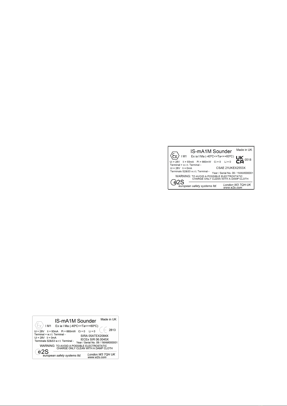
SPECIAL CONDITIONS FOR SAFE USE (as stated in the
EC Type Examination Certificate SIRA 05ATEX2084X)
Conditions for IS-mA1M Sounder
The equipment has an ingress protection rating of IP65.
However, if it has been supplied without cable entry devices,
then the user shall ensure that the devices that are fitted will
provide an ingress protection that is appropriate to the
environment in which it is installed i.e. IP20 or better. If only
one of the two cable entries are used, then the unused entry
'knockout' shall be left intact or fitted with a blanking device
that ensures ingress protection appropriate to the
environment in which it is installed i.e. IP20 or better.
The total capacitance connected to terminals + wrt - (i.e. the
capacitance of the cable plus any other capacitance) shall
not exceed 83nF.
The enclosure is non-conducting and may generate an
ignition-capable level of electrosatic charges under certain
extreme conditions. The user should ensure that the
equipment is not installed in a location where it may be
subjected to external conditions that might cause a build-up
of electrostatic charges on non-conducting surfaces,
additionally, cleaning of the equipment should be done only
with a damp cloth.
The equipment shall only be supplied via Terminals + w.r.t.
Terminals - from a barrier having a maximum open circuit
voltage Uo that is < 28V and a maximum short circuit current
Io that is < 93mA, where Io is resistively limited. The barrier
shall be ATEX certified by a notified body.
4.2 Equipment Category
The IS-mA1M sounder is intended for use in mines
endangered by fire damp and/or coal dust and can remain
functional, even in the event of incidents where an explosive
is atmosphere present.
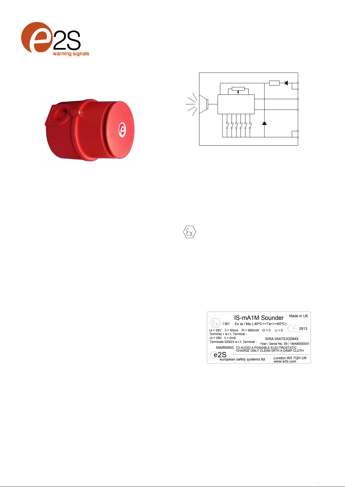
4.3 Terminals + and -
Power is supplied to the sounder via the + and – terminals
which have the following input safety parameters:
Ui = 28V
Ii = 93mA
Pi = 660mW
Ci = 0 Li = 0
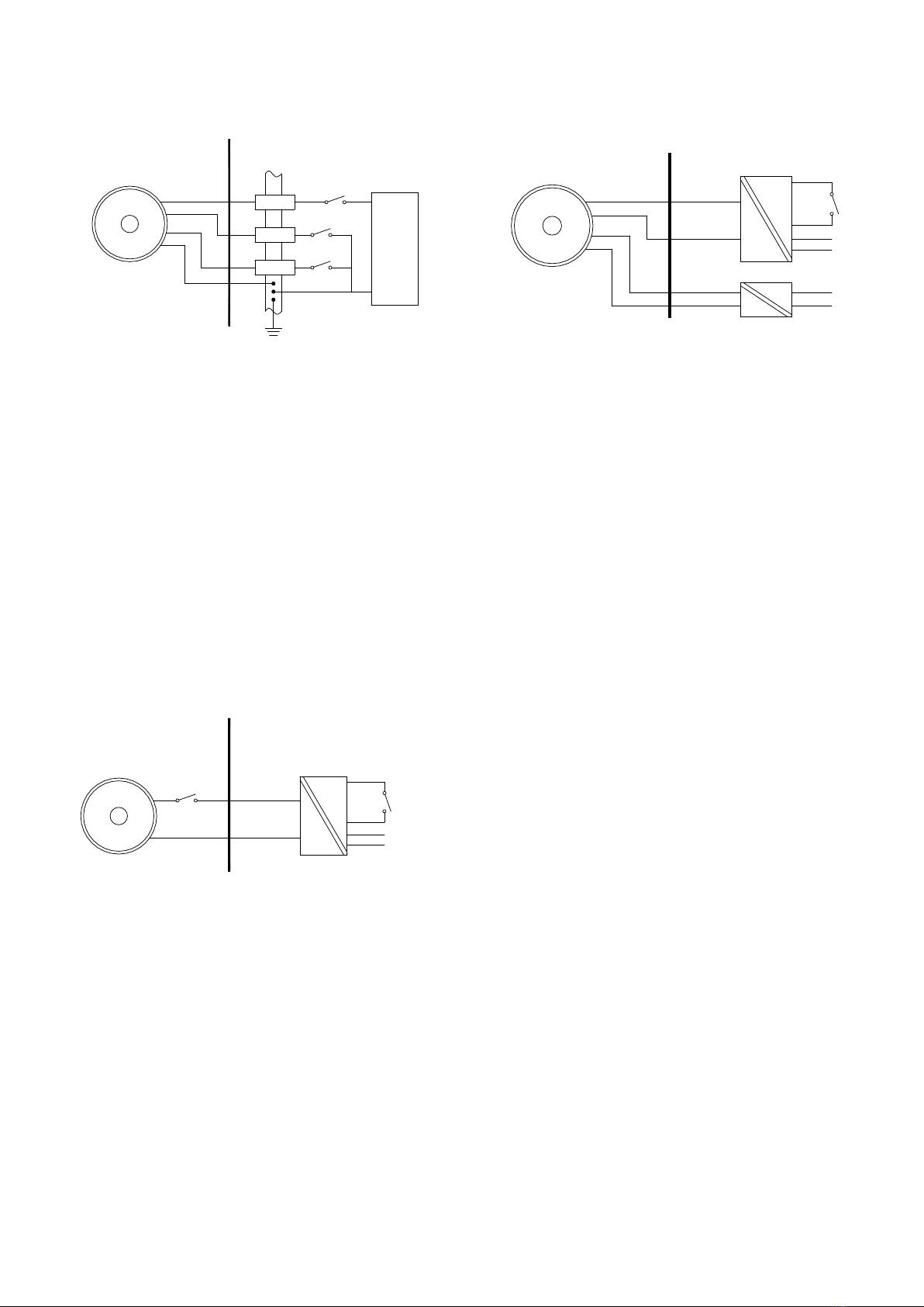
The IS-mA1M sounder may be powered from an ATEX
certified Zener barrier or galvanic isolator which have output
parameters equal to or less than 28V, 93mA and 660mW,
where Io is resistively limited. The cable parameters stated
on the selected Zener barrier or galvanic isolator certificate
must be observed.
Up to three IS-mA1M sounders can be connected in parallel
and powered from a common barrier or isolator. Connecting
two sounders in parallel will reduce the output from each by
about 3dB. Three sounders should only be powered from a
common supply when the maximum supply voltage is
available.
4.4 Terminals S2 and S3
When terminals S2 or S3 are connected to 0V (- terminal) the
sounder output tone changes to the second or third stage
alarm respectively. The input safety parameters for these
terminals are:
Ui = 28V
Ii = 0mA
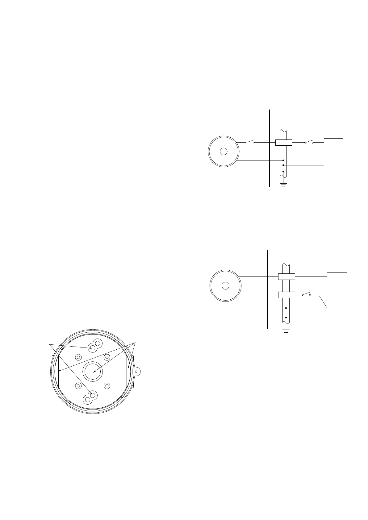
Because the permitted input current is zero, these terminals
may only be connected to a diode return barrier, an
intrinsically safe relay or a galvanic isolator, all of which must
have been certified by an EC Notified Body. Only diode return
barriers with a voltage drop of less than 0.9V may be used.
Alternatively, these terminals may be connected directly to a
mechanically activated switch within the hazardous area.
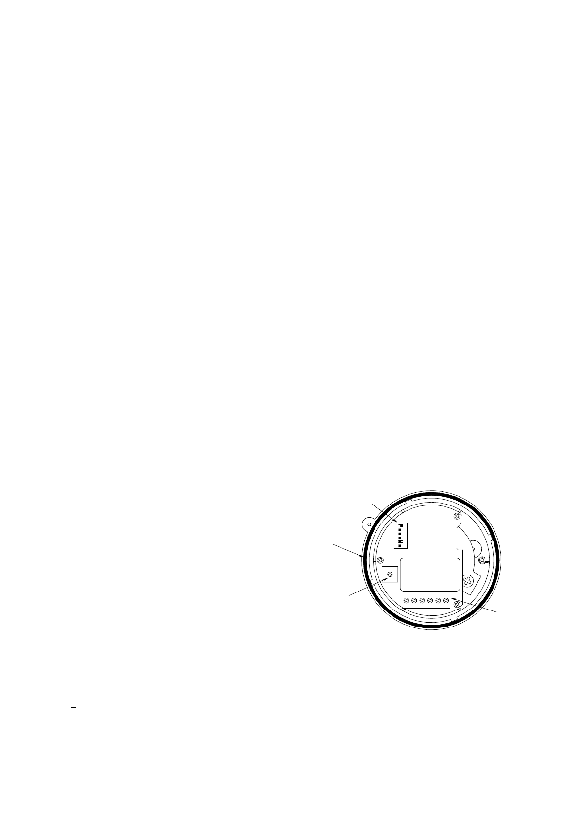
Volume Control
'O' Ring Seal
+ + - - S2 S3
IS-mA1M Sounder
1 2 3 4 5 6
Input Terminals
Tone Setting
Switches 1-6
Fig 2 Location of field terminals and controls.

_______________________________________________________________________________________________________________________________
European Safety Systems Ltd. Impress House, Mansell Road, Acton, London W3 7QH www.e2s.com Tel: +44 (0)20 8743 8880
Document No. D251-00-051-IS Issue 1 12-08-2022 Sheet 3 of 6
Tone Selection – To select the required first stage tone set the tone switches 1 to 6 (see
Fig 2) to the tone setting shown in the table below. The table also shows which 2nd and 3rd
stage tones are available for use with the selected first stage tone if more than one tone
output stage is required.
Tone
Number
Tone Description
Switch
Settings
1 2 3 4 5 6
Second
Stage
Alarm
Third
Stage
alarm
Tone 1
Tone 2
Tone 3
Tone 4
Tone 5
Tone 6
Tone 7
Tone 8
Tone 9
Tone 10
Tone 11
Tone 12
Tone 13
Tone 14
Tone 15
Tone 16
Tone 17
Tone 18
Tone 19
Tone 20
Tone 21
Tone 22
Tone 23
Tone 24
Tone 25
Tone 26
Tone 27
Tone 28
Tone 29
Tone 30
Tone 31
Tone 32
Tone 33
Tone 34
Tone 35
Tone 36
Tone 37
Tone 38
Tone 39
Tone 40
Tone 41
Tone 42
Tone 43
Tone 44
Tone 45
Tone 46
Tone 47
Tone 48
Tone 49
Continuous 340Hz
Alternating 800/1000Hz @ 0.25s intervals
Slow whoop 500/1200Hz @ 0.3Hz with 0.5s gap repeated
Sweeping 500/1000Hz @ 1Hz
Continuous 2400Hz
Sweeping 2400/2900Hz @ 7Hz
Sweeping 2400/2900Hz @ 1Hz
Siren 500/1200/500Hz @ 0.3Hz
Sawtooth 1200/500Hz @ 1Hz - D.I.N.
Alternating 2400/2900Hz @ 2Hz
Intermittent 1000Hz @ 1Hz
Alternating 800/1000Hz @ 0.875Hz
Intermittent 2400Hz @ 1Hz
Intermittent 800Hz 0.25s ON, 1s OFF
Continuous 800Hz
Intermittent 660Hz 150Ns ON, 150ms OFF
Alternating 544Hz (100ms) / 440Hz (400ms) – NFS 32-001
Intermittent 660Hz 1.8s ON, 1.8s OFF
Sweep 1400Hz to1600Hz up 1s 1600Hz to 1400Hz down 0.5s
Continuous 660Hz
Alternating 554/440Hz @ 1Hz
Intermittent 544Hz @ 0.875Hz
Intermittent 800Hz @ 2Hz
Sweeping 800/1000Hz @ 50Hz
Sweeping 2400/2900Hz @ 50Hz
Simulated bell
Continuous 554Hz
Continuous 440Hz
Sweeping 800/1000Hz @ 7Hz
Continuous 300Hz
Sweeping 660/1200 @ 1Hz
Two Tone Chime
Intermittent 745Hz
Alternating 1000/2000Hz @ 0.5s – Singapore
420Hz @ 0.625s - Australian Alert
500-1200Hz 3.75s / 0.25s - Australian Evacuate
Continuous 1000Hz
Continuous 2000Hz
Intermittent 800Hz 0.25s ON 1s OFF
Alternating 544Hz (100ms) / 440Hz (400ms) – NFS 32-001
Motor Siren – Slow rise to 1200Hz
Motor Siren – Slow rise to 800Hz
Continuous 1200Hz
Motor Siren – Slow rise to 2400Hz
Intermittent 1000Hz 1s ON, 1s OFF
Sawtooth 1200/500Hz @ 1Hz - D.I.N. (PFEER P.T.A.P)
Intermittent 1000Hz 1s ON, 1s OFF – PFEER General Alarm
420Hz @ 0.625s - Australian Alert
500-1200Hz 3.75s / 0.25s - Australian Evacuate
0 0 0 0 0 0
1 0 0 0 0 0
0 1 0 0 0 0
1 1 0 0 0 0
0 0 1 0 0 0
1 0 1 0 0 0
0 1 1 0 0 0
1 1 1 0 0 0
0 0 0 1 0 0
1 0 0 1 0 0
0 1 0 1 0 0
1 1 0 1 0 0
0 0 1 1 0 0
1 0 1 1 0 0
0 1 1 1 0 0
1 1 1 1 0 0
0 0 0 0 1 0
1 0 0 0 1 0
0 1 0 0 1 0
1 1 0 0 1 0
0 0 1 0 1 0
1 0 1 0 1 0
0 1 1 0 1 0
1 1 1 0 1 0
0 0 0 1 1 0
1 0 0 1 1 0
0 1 0 1 1 0
1 1 0 1 1 0
0 0 1 1 1 0
1 0 1 1 1 0
0 1 1 1 1 0
1 1 1 1 1 0
0 0 0 0 0 1
1 0 0 0 0 1
0 1 0 0 0 1
1 1 0 0 0 1
0 0 1 0 0 1
1 0 1 0 0 1
0 1 1 0 0 1
1 1 1 0 0 1
0 0 0 1 0 1
1 0 0 1 0 1
0 1 0 1 0 1
1 1 0 1 0 1
0 0 1 1 0 1
1 0 1 1 0 1
0 1 1 1 0 1
1 1 1 1 0 1
0 0 0 0 1 1
Tone 2
Tone 17
Tone 2
Tone 6
Tone 3
Tone 7
Tone 10
Tone 2
Tone 15
Tone 7
Tone 2
Tone 4
Tone 15
Tone 4
Tone 2
Tone 18
Tone 2
Tone 2
Tone 2
Tone 2
Tone 2
Tone 2
Tone 6
Tone 29
Tone 29
Tone 2
Tone 26
Tone 2
Tone 7
Tone 2
Tone 26
Tone 26
Tone 2
Tone 38
Tone 36
Tone 35
Tone 9
Tone 34
Tone 23
Tone 31
Tone 2
Tone 2
Tone 2
Tone 2
Tone 38
Tone 47
Tone 46
Tone 49
Tone 26
Tone 5
Tone 5
Tone 5
Tone 5
Tone 20
Tone 5
Tone 5
Tone 5
Tone 2
Tone 5
Tone 5
Tone 5
Tone 5
Tone 5
Tone 5
Tone 5
Tone 27
Tone 5
Tone 5
Tone 5
Tone 5
Tone 5
Tone 5
Tone 5
Tone 5
Tone 15
Tone 5
Tone 5
Tone 5
Tone 5
Tone 5
Tone 15
Tone 5
Tone 45
Tone 5
Tone 5
Tone 45
Tone 45
Tone 17
Tone 27
Tone 5
Tone 5
Tone 5
Tone 5
Tone 34
Tone 37
Tone 37
Tone 5
Tone 37

_______________________________________________________________________________________________________________________________
European Safety Systems Ltd. Impress House, Mansell Road, Acton, London W3 7QH www.e2s.com Tel: +44 (0)20 8743 8880
Document No. D251-00-051-IS Issue 1 12-08-2022 Sheet 4 of 6
4.5 Other intrinsic safety certifications
Please contact European Safety Systems Ltd. for details of
non-European intrinsic safety approvals.
5) Installation
IS-mA1M minialarm sounders should only be installed by
trained competent personnel.
5.1 Mounting
The IS-mA1M minialarm sounder may be secured to any flat
surface by inserting two mounting screws through the back of
the round base (see figure 3). The enclosure provides IP65
protection and is suitable for installation in exterior locations
provided that the area around the two mounting screws
through the back of the base moulding has been sealed and
that suitable cable glands with the required IP rating have
been used.
5.2 Installation procedure
a. Unscrew the sounder unit security screw and remove
the sounder section from the base by turning it anti-
clockwise. Ensure that the ‘O’ ring seal remains in
place.
b. Remove the required 20mm knockout section(s)
depending on system wiring and mount the base to a
flat surface by inserting two screws through the back
of the base.
c. Fit the required number of 20mm cable glands or
conduit entries into the base and connect the field
wiring to the appropriate sounder terminals as shown
in section 6 and fig 2 of this manual. The power supply
terminals + and - are duplicated so that sounders may
be connected in parallel, or an end of line monitoring
resistor may be fitted.
d. Select the required output tone by positioning the six
switches as shown in Table 1 and Fig 2.
e. Apply power to the sounder and adjust the internal
volume control to provide the required sound level.
f. Check that the ‘O’ ring seal is correctly located on the
sounder section (see Fig. 2) and insert the sounder
section into the base. Push it fully home and turn it
clockwise to align the mouldings before tightening the
security screw.
Fit mounting screws
through base 20mm knockouts
Fig 3 Mounting Sounder Base.
6) Electrical System Design For Installation In
Hazardous Areas Using Zener Barriers
6.1 Single stage alarm
If the control switch is in the positive supply, or the power
supply is being turned on and off, only a single channel Zener
barrier is required as shown in Fig 4. This circuit may also be
used if the sounder is being controlled by a mechanically
activated switch on the hazardous area side of the barrier.
Safe Area
Hazardous Area
+
-
IS-mA1M
Sounder
0V
+
Power
Supply
Barrier
On/Off
28V 93mA
Positive
Fig 4 Single stage alarm using single channel barrier.
If the control switch must be in the negative supply, the circuit
shown in Fig 5 may be used. Any diode return barrier certified
Ex ia by a EC Notified Body may be used, providing its
voltage drop is less than 0.9V.
Safe Area
Hazardous Area
-
IS-mA1M
Sounder
+
0V
+
Power
Supply
Diode Return
Barrier
Barrier
On/Off
28V 93mA
Positive
Fig 5 Single stage alarm using two channel barrier.
6.2 Multi-stage alarm
Connecting terminal S2 to 0V activates the second stage
alarm, and similarly terminal S3 for the third stage alarm. Fig
6 shows how the diode return barriers may be used. If only
two stages of alarm are required the third stage barrier
should be omitted, the 28V 93mA barrier and the single diode
return channel may then be contained in one package.

_______________________________________________________________________________________________________________________________
European Safety Systems Ltd. Impress House, Mansell Road, Acton, London W3 7QH www.e2s.com Tel: +44 (0)20 8743 8880
Document No. D251-00-051-IS Issue 1 12-08-2022 Sheet 5 of 6
S3
S2
-
IS-mA1M
Sounder
+
0V
+
Power
Supply
Diode Return
Barrier
Diode Return
Barrier
Barrier
3rd Stage
2nd Stage
On/Off
28V 93mA
Positive
Hazardous Area Safe Area
Fig 6 Multi stage alarm using Zener barriers.
7) Electrical System Design For Installation In
Hazardous Areas Using Galvanic Isolators
Galvanic isolators do not require a high integrity earth
connection. For small systems where a high integrity earth is
not already available, the use of galvanic isolators often
reduces the overall installation cost and simplifies design.
7.1 Single stage alarm
The IS-mA1M minialarm sounder may be powered by any
galvanic isolator having output parameters within the limits
specified in section 4.3, which has been certified Ex ia by an
EC Notified Body. The sounder may be controlled by turning
the galvanic isolator on and off, or by a mechanically
activated switch on the hazardous area side of the isolator.
Safe Area
Hazardous Area
IS-mA1M
Sounder
+
--
+
Galvanic
Isolator
Power
Fig 7 Single stage alarm using galvanic isolator.
7.2 Multi stage alarm
The IS-mA1M sounder second and third stages may be
activated by using Galvanically Isolated Relays that have
output parameters within the limits specified in section 4.4.
which have been certified Ex ia by an EC Notified Body.
Safe Area
Hazardous Area
S2
-
IS-mA1M
Sounder
+
-
Galvanic Isolated Relay
-
Galvanic Isolator
+
Power
Power
Fig 8 Multi stage alarm using galvanic isolated relays
8) Cable Parameters
The maximum permitted cable parameters are as specified
on the certificate of the Zener barrier or galvanic isolator that
has been selected for the installation. Normally the limits are
not restrictive, but care should be taken not to exceed a
capacitive limit of 83nF for installations when very long cables
are used.
9) Volume Control
The output level of the IS-mA1M sounder can be set by
adjusting the volume control potentiometer (see Fig 2).
10) Maintenance
The sounder should be regularly inspected to ensure that it
has not been damaged. Frequency of inspection depends
upon environmental conditions, but initially we recommend
that this should be done annually.
No attempt should be made to repair a faulty ISmA1M
sounder. Suspect sounders must be returned to
European Safety Systems Ltd. or to your local agent for
repair.
11) Guarantee
Sounders that fail within the guarantee period should be
returned to European safety Systems Ltd. It is helpful if a
brief description of the fault symptoms is provided.
12) Customer Comments
European Safety Systems Ltd. is always pleased to receive
comments from customers about our products and services.
All communications are acknowledged and whenever
possible, suggestions are implemented.

_______________________________________________________________________________________________________________________________
European Safety Systems Ltd. Impress House, Mansell Road, Acton, London W3 7QH www.e2s.com Tel: +44 (0)20 8743 8880
Document No. D251-00-051-IS Issue 1 12-08-2022 Sheet 6 of 6
IECEx Approval
The IS-mA1M Sounder has also been approved to the IECEx
scheme.
The installation requirements for IS-mA1M sounders
approved to the IECEx scheme are the same as the
installation requirements for IS-mA1M sounders approved to
the ATEX directive.
Certificate No. IECEx SIR 06.0045X
Marking: Ex ia I Ma (-40ºC <= Ta <= +60ºC)
Standards: IEC 60079-0:2017
IEC 60079-11:2011
IEC 60079-26:2014-10
CONDITIONS OF CERTIFICATION (as stated on the IECEx
Certificate of Conformity IECEx SIR 06.0045X)
The equipment has an ingress protection rating of IP65.
However, if it has been supplied without cable entry
devices, then the user shall ensure that the devices that
are fitted will provide an ingress protection that is
appropriate to the environment in which it is installed i.e.
IP20 or better. If only one of the two cable entries are
used, then the unused entry ‘knockout’ shall be left intact
or fitted with a blanking device that ensures ingress
protection appropriate to the environment in which it is
installed i.e. IP20 or better
The total capacitance connected to Terminal + w.r.t. –
(i.e. the capacitance of the cable plus any other
capacitance) shall not exceed 83 nF.
The enclosure is non-conducting and may generate an
ignition-capable level of electrostatic charges under
certain extreme condition. The user should ensure that
the equipment is not installed in a location where it may
be subjected to external conditions that might cause a
build-up of electrostatic charges on non-conducting
surfaces, additionally, cleaning of the equipment should
be done only with a damp cloth.
The equipment shall only be supplied via Terminals +
w.r.t. Terminal – from a barrier having a maximum open
circuit voltage Uo that is ≤28 V and a maximum short
circuit current Io that is ≤93 mA, where Io is resistively
limited. The barrier shall be ATEX certified by a notified
body.
The IS-mA1 sounders are marked with the certification
requirements for the ATEX and IECEx and approvals.
UKEX Approval
The IS-mA1M Sounder has also been approved to the UKEX
scheme.
The installation requirements for IS-mA1M sounders
approved to the UKEX scheme are the same as the
installation requirements for IS-mA1M sounders approved to
the ATEX directive.
Certificate No. CSAE 21UKEX2553X
Marking: Ex ia I Ma (-40ºC <= Ta <= +60ºC)
Standards: EN IEC 60079-0:2018
EN60079-11:2012
EN60079-26:2014 Ed 3.0
The IS-mA1M sounders are marked with the certification
requirements for the UKEX approval.

E2S Telephone: +44 (0)20 8743 8880 Fax: +44 (0)20 8740 4200 Email: sale[email protected] www.e2s.com DC-011_Issue_J (IS-Mini) - Page 1 of 2 - QAF_252_Issue_5
EU Declaration of Conformity
Manufacturer: European Safety Systems Ltd.
Impress House, Mansell Road, Acton
London, W3 7QH
United Kingdom
Authorised Representative: E2S Warnsignaltechnik UG
Charlottenstrasse 45-51
72764 Reutlingen
Germany
Equipment Type: IS-mA1, IS-mA2, IS-mA3, IS-mB1, IS-mC1, IS-mA1M
Directive 2014/34/EU: Equipment and Protective Systems for use in Potentially Explosive Atmospheres (ATEX)
Notified Body for EU type Examination (Module B):
Sira Certification Service
Notified Body No.: 2813
CSA Group Netherlands B.V, Utrechtseweg 310, 6812 AR, Arnhem, Netherlands
EU-type Examination Certificate (Module B):
SIRA 05ATEX2084X
Notified Body for Quality Assurance Notification / Conformity to EU-type
based on
quality assurance of the production process (Module D):
Sira Certification Service
Notified Body No.: 2813
CSA Group Netherlands B.V, Utrechtseweg 310, 6812 AR, Arnhem, Netherlands
Quality Assurance Notification (Module D):
SIRA 05 ATEX M342
Provisions fulfilled by the equipment:
II 1 G Ex ia IIC T4 Ga (-40 °C ≤ Ta ≤ +60 °C) or
I M1 Ex ia I Ma (-40 °C ≤ Ta ≤ +60 °C)
Standards applied:
EN IEC 60079-0:2018
EN 60079-11:2012
IEC 60079-26:2014
Regulation EU No. 305/2011: Construction Products Regulation (CPR) –IS-mA1 (tones 2, 3, 9, 15, 16, 17) only
Notified Product Certification Body for Certificate of Constancy of
Performance or EC Type Examination Certificate and continuous
surveillance, assessment and evaluation of factory production control:
VdS Schadensverhütung GmbH
Notified Body No.: 0786
Amsterdamer Str 172-174, 50735 Köln, Germany
Certificate of Constancy of Performance or EC Type Examination
Certificate:
0786-CPD-20338
Standards applied:
EN 54-3:2001 + A1:2002 + A2:2006
Directive 2014/30/EU: Electromagnetic Compatibility Directive (EMC)
Standards applied:
EN 61000-6-1:2007
EN 61000-6-2:2005
EN 61000-6-3:2007 / A1:2011 / AC: 2012
EN 61000-6-4:2007 / A1: 2011
Directive 2011/65/EU: Restriction of the use of certain hazardous substances in electrical and electronic equipment (RoHS)
The product and all the components contained within it are in accordance with the restriction of the use of hazardous substances in electrical and electronic
equipment, including amendment by Directive 2015/863/EU.
Regulation (EC) 1907/2006: Registration, Evaluation, Authorisation and Restriction of Chemicals (REACH)
The product and all the components contained within it are free from substances of very high concern.
Other Standards and Regulations
EN 60529:1992+A2:2013 - Degrees of protection provided by enclosures (IP code) –enclosure rated IP65

E2S Telephone: +44 (0)20 8743 8880 Fax: +44 (0)20 8740 4200 Email: sale[email protected] www.e2s.com DC-011_Issue_J (IS-Mini) - Page 2 of 2 - QAF_252_Issue_5
Martin Streetz
Document No.:
DC-011_Issue_J
Quality Assurance Manager
Date and Place of Issue:
London, 23/12/2020
EU Declaration of Conformity
On behalf of European Safety Systems Ltd., I declare that, on the date the equipment accompanied by this declaration is placed on the market, the equipment
conforms with all technical and regulatory requirements of the above listed directives, regulations and standards.
This Declaration is issued under the sole responsibility of the manufacturer.

E2S Telephone: +44 (0)20 8743 8880 Fax: +44 (0)20 8740 4200 Email: sal[email protected] www.e2s.com DC-088_Issue_A (IS-Mini) - Page 1 of 2 - QAF_252_Issue_5
UKCA Declaration of Conformity
Manufacturer: European Safety Systems Ltd.
Impress House, Mansell Road, Acton
London, W3 7QH
United Kingdom
Equipment Type: IS-mA1, IS-mA2, IS-mA3, IS-mB1, IS-mC1, IS-mA1M
Directive UKSI 2016:1107 (as amended by UKSI 2019:696) – Schedule 3A, Part 1 : Product or Protective System Intended for use in Potentially Explosive Atmospheres
(UKCA)
Notified Body for UK
type Examination
(Module B)
:
Sira Certification Service
Notified Body No.: 0518
Rake Lane, Eccleston, Chester CH4 9JN, UK
UK
-
type Examination Certificate
(Module B)
:
CSAE 21
UKEX2553X
Notified Body for Quality Assurance
Notification
/ Conformity to EU
-
type
based on
quality assurance of the production process (Module D):
Sira Certification Service
Notified Body No.: 0518
Rake Lane, Eccleston, Chester CH4 9JN, UK
Quality Assurance Notification
(Module D)
:
CSAE 22UKQAN0046
Provisions fulfilled by the equipment:
II 1 G Ex ia IIC T4 Ga (
-
40 °C
≤ Ta ≤ +60 °C) or
I M1 Ex ia I Ma (-40 °C ≤ Ta ≤ +60 °C)
Standards applied:
EN
IEC
60079
-
0:201
8
EN 60079-11:2012
IEC 60079-26:2014
Regulation EU No. 305/2011: Construction Products Regulation (CPR) – IS-mA1 (tones 2, 3, 9, 15, 16, 17) only
Notified
Product Certification
Body for
Certificate of Constancy of
Performance or EC Type Examination Certificate and continuous
surveillance, assessment and evaluation of factory production control:
VdS Schadensverhütung GmbH
Notified Body No.: 0786
Amsterdamer Str 172-174, 50735 Köln, Germany
Certificate of Constancy of Performance or EC Type Examination
Certificate:
0786
-
CPD
-
20338
Standards applied:
EN 54
-
3:2001
+
A1:2002
+
A2:2006
Directive 2014/30/EU: Electromagnetic Compatibility Directive (EMC)
Standards applied:
EN 61000
-
6
-
1:2007
EN 61000-6-2:2005
EN 61000-6-3:2007 / A1:2011 / AC: 2012
EN 61000-6-4:2007 / A1: 2011
Directive 2011/65/EU: Restriction of the use of certain hazardous substances in electrical and electronic equipment (RoHS)
The product and all the components contained within it are in accordance with the restriction of the use of hazardous substances in electrical and electronic
equipment, including amendment by Directive 2015/863/EU.
Regulation (EC) 1907/2006: Registration, Evaluation, Authorisation and Restriction of Chemicals (REACH)
The product and all the components contained within it are free from substances of very high concern.
Other Standards and Regulations
EN 60529:1992+A2:2013 - Degrees of protection provided by enclosures (IP code) – enclosure rated IP65

E2S Telephone: +44 (0)20 8743 8880 Fax: +44 (0)20 8740 4200 Email: sal[email protected] www.e2s.com DC-088_Issue_A (IS-Mini) - Page 2 of 2 - QAF_252_Issue_5
Martin Streetz Document No.: DC-088_Issue_A
Quality Assurance Manager Date and Place of Issue: London, 04/02/2022
UKCA Declaration of Conformity
On behalf of European Safety Systems Ltd., I declare that, on the date the equipment accompanied by this declaration is placed on the market, the equipment
conforms with all technical and regulatory requirements of the above listed directives, regulations and standards.
This Declaration is issued under the sole responsibility of the manufacturer.
Other manuals for IS-mA1M
1
Table of contents
Other E2S Marine Equipment manuals

E2S
E2S D105 AlertAlarm User manual

E2S
E2S D2xB1LD2 User manual

E2S
E2S STExC1 User manual

E2S
E2S DL112H User manual

E2S
E2S Minialarm IS-mA1 User manual

E2S
E2S E2xS1RDC024 Manual

E2S
E2S A105N APPELLO User manual

E2S
E2S D1xS1RDC024-D User manual

E2S
E2S SONF1 Series User manual

E2S
E2S BExCS110-05D-PDC012 User manual
Popular Marine Equipment manuals by other brands

New Age
New Age PRM 302D Workshop manual

Bennett
Bennett HIGH FLOW H35 instruction manual

AML Oceanographic
AML Oceanographic AML-1 RT user manual

Lecomble & Schmitt
Lecomble & Schmitt VHM 26 DTP Mounting instructions

System Sensor
System Sensor MASS12LO Installation and maintenance instructions

B&G
B&G H5000 Pilot installation guide