7.3. Cable Selection and Connections
When selecting the cable size, consideration must be given to
the input current that each unit draws (see table 1), the number
of sounders on the line and the length of the cable runs. The
cable size selected must have the necessary capacity to
provide the input current to all of the sounders connected to
the line.
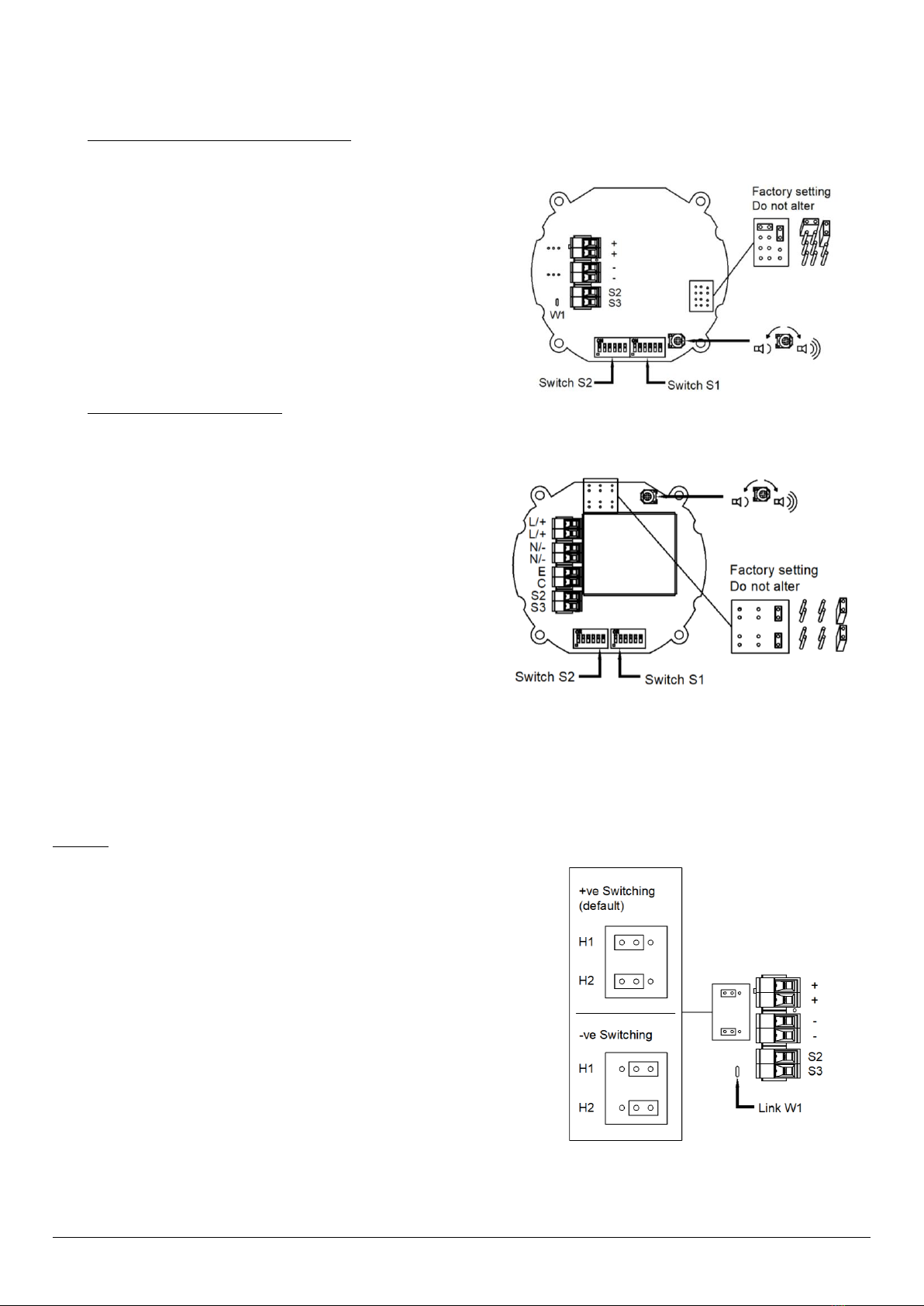
Electrical connections are to be made into the terminal blocks
on the PCBA located in the flameproof enclosure using solid
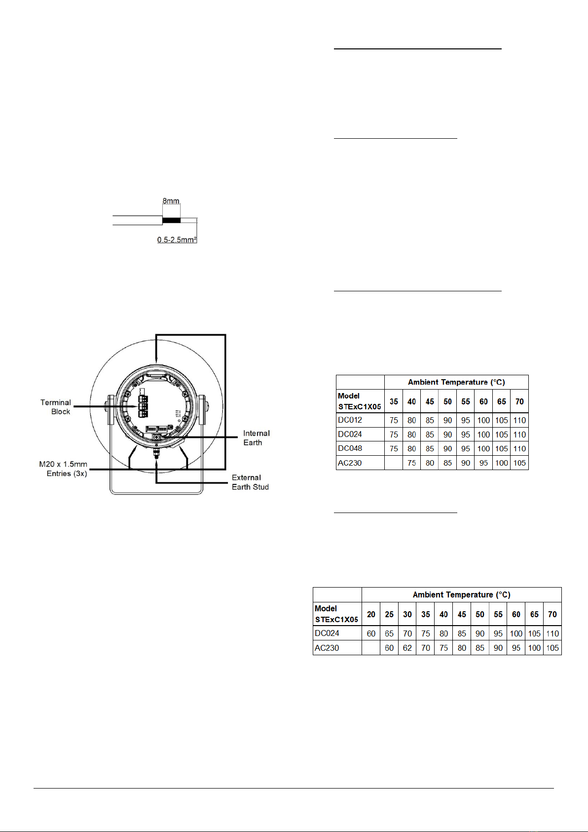
wire 0.5-4mm² / AWG 20-12 or stranded wire, sizes 0.5-
2.5mm² / AWG 24-14. Wire insulation needs to be stripped
8mm. Wires may be fitted securely with crimped ferrules.
Figure 5: Wire Preparation.
Terminal screws need to be tightened down with a tightening
torque of 0.45 Nm / 5 Lb-in. An 8-way terminal block is
provided on the AC Sounder, and a 6-way terminal block is
provided on the DC Sounder.
Figure 6: STExC1 Entries and Terminal Block Location.
When connecting wires to the terminals great care should be
taken to dress the wires so that when the cover is inserted into
the chamber the wires do not exert excess pressure on the
terminal blocks. This is particularly important when using
cables with large cross-sectional areas such as 2.5mm².
Earthing
Both AC and DC combined sounder-beacon units must be
connected to an earth according to EN/IEC 60079/14. The
units are provided with internal and external earth terminals
which are both located on the terminal chamber section of the
unit (see figure 6).
External earthing connections should be made to the M5 earth
stud, using a ring crimp terminal to secure the earth conductor
to the earth stud between the two M5 stainless steel flat
washers, then reassemble the M5 spring washer and tighten
the M5 nut to ensure that the cable lug is secured against
loosening and twisting. The external earth conductor should be
at least 4mm2in size.
ATEX / IECEx & UKEx Requirements Only
Internal earthing connections should be made to the
Internal Earth terminal in the base of the housing using
a ring crimp terminal to secure the earth conductor under
the earth clamp. The earth conductor should be at least
equal in size and rating to the incoming power
conductors.
NEC / CEC Requirements Only
Internal earthing connections should be made to the
Internal Earth terminal in the base of the housing using
a ring crimp terminal to secure the earth conductor under
the earth clamp. The earth conductor should be at least
equal in size and rating to the incoming power
conductors but at least a mini mum of 0.82mm2 / 18AWG
in size.
7.4. Cable Glands, Blanking Elements & Adapters
Follow the minimum temperature ratings of cables and cable
glands according to the approvals applied.
ATEX / IECEx & UKEx Requirements Only
For high ambient temperatures the cable entry
temperature may exceed 70ºC or the cable branching
point temperature may exceed 80ºC and therefore
suitable heat resisting cables and cable glands must be
used, with a rated service temperature at least as stated
below:
Table 2: ATEX / IECEx & UKEx Min. Ratings of Cables &
Cable Glands.
NEC / CEC Requirements Only
For high ambient temperatures the cable entry
temperature may exceed 60ºC or the cable branching
point temperature may exceed 60ºC and therefore
suitable heat resisting cables and cable glands must be
used, with a rated service temperature at least as stated
below:
Table 3: NEC / CEC Min. Ratings of Cables & Cable Glands.