E2S IS-A105N User manual

_______________________________________________________________________________________________________________________________
EuropeanSafetySystemsLtd. Impress House, MansellRoad, Acton, London W37QHsales@e2s.com Tel: +44 (0)20 8743 8880
www.e2s.com Fax: +44 (0)20 8740 4200
DocumentNo. IS4501 Issue E27-11-09 Sheet 1of6
INSTRUCTIONMANUAL
IS-A105N
IntrinsicallySafeSounder
1)Introduction
TheIS-A105Nisan ATEX andIECExcertifiedintrinsically
safesounderwhichproducesaloudwarningsignalina
hazardousarea.Forty-ninefirststagealarmsoundscan be
selected byinternalswitchesandeachonecan be externally
changed toasecondorthirdstage alarmsound.The
soundermaybe usedinall gasgroupsIIA,IIBandIIC.The
IS-A105Nsoundermaybeused inconjunctionwithan IS-
L101Lintrinsicallysafebeacon,allowingacombinedaudible
andvisualalarmtobe constructed.
2)Description
Fig1showsasimplifiedblockdiagramofan IS-A105N
sounder.Thedeviceoperatesimmediatelypowerisapplied
tothe+and–terminalswhichareduplicated toallowa
secondsoundertobeconnectedinparallel,orforan end of
linemonitoringresistortobeinstalled.Theoutputtoneis
defined bythepositionsofthesixinternalswitchesandthis
tonecan be changedtoasecondorthirdstage alarmtoneby
connectingterminalsS2orS3to0V.The tone generatoris
crystalcontrolledtoensurethatwhentwosoundersare
started atthesametimetheoutputtonesremain
synchronised.
3) SupplyVoltage
TheIS-A105Nsounderhasbeendesigned tooperateina
hazardousareafroma24Vdcsupplyvia28V93mAresistive
ATEXandIECExcertifiedZenerBarriersorGalvanic
Isolators.Thesoundersmaybe testedorused insafeareas
withoutaZenerbarrierorgalvanicisolator,butatsupply
voltagesabove16Vtheinternalcurrentlimit willfunctionand
thereforeitisrecommendedthattheyarenotoperated
continuouslywithadirect supplygreaterthan16V.
-
-
IS-A105NSounder
VolumeControl
ToneSelection Switches
ToneGenerator
+
+
S2
S3
Fig1Simplifiedblockdiagram
4) IntrinsicSafetyCertification
4.1ATEXcertificate
TheIS-A105Nsounder complieswith thefollowing
standards:-
EN60079-0:2006
EN60079-11:2007
EN60079-26:2007
IEC60079-0:2007 (usedforguidanceinrespectofmarking)
TheEC-TypeExaminationCertificateSIRA04ATEX2301X
hasbeenissued bytheNotified BodySira.Thisconfirms
compliancewiththeEuropean ATEX Directive94/9/ECfor
GroupII,Category1Gequipment. Thesoundercarriesthe
CommunityMarkandsubjecttolocalcodesof practice,may
beinstalled inanyofthe EEAmembercountries.This
instructionsheetdescribesinstallationswhichconformto
EN60079:Part14:2008ElectricalInstallationinHazardous
Areas.Whendesigningsystemsforinstallationoutside the
UK, thelocalCodeofPracticeshouldbeconsulted.
1) Thecertificationmarkingisasfollows:
e2S european safetysystemsltd.
SIRA04ATEX2301X
0518
IS-A105NSounder
London W37QHUK
www.e2s.com
Year/ SerialNo.
09/ 1S000001
WARNINGS:
IECExSIR04.0038X
Term. +w.r.t. Term. -Ui=28VIi=93mA
Pi=660mWCi=0Li=0
Term. S2&S3w.r.t. Term. -Ui=28VIi=0mA
FM
APPROVED
Toavoid apossible electrostatic
charge onlyclean withadampcloth
Topreventignitionofflammable orcombustible
atmospheres,disconnectpowerbeforeservicing
Substitution ofcomponentsmayimpairsafety
ISClassI,Zone 0,AExia IICT4
ISClassl,Division 1,GroupsA,B,C,D
II1GEx ia IICT4Ga(-40ºC<=Ta<= +60°C)
Control Drawing No.D4528
TheIS
-
A105NsounderisCEmarked for
compliancewith theEuropean
Explosive AtmospheresDirective
94/9/ECand theEuropean EMC
Directive89/336/EEC
II1GExiaIICT4Ga(-40ºC<= Ta<= +60ºC)

_______________________________________________________________________________________________________________________________
EuropeanSafetySystemsLtd. Impress House, MansellRoad, Acton, London W37QHsales@e2s.com Tel: +44 (0)20 8743 8880
www.e2s.com Fax: +44 (0)20 8740 4200
DocumentNo. IS4501 Issue E27-11-09 Sheet 2of6
2) Theequipmentmaybeused inzones0,1and2
withflammablegasesandvapourswithapparatus
groupsIIA,IIB&IICandwithtemperatureclasses
T1, T2, T3andT4.
3) Theequipmentisonlycertifiedforuseinambient
temperaturesintherange -40oCto+60oCand
shouldnot be usedoutsidethisrange.
4) Thecertificatenumberhasan ‘X’suffix,which
indicatesthatthecertificatecontainsoneofmore
specialconditionsforsafeuse.Thoseinstallingor
inspectingtheequipmentshouldrefertothissection
ofthecertificate.
5) Theequipmenthasnotbeenassessedasasafety-
related device(asreferred tobyDirective94/9/EC
AnnexII, clause1.5).
6) Installationofthisequipment shall be carried out by
suitably-trained personnelinaccordancewiththe
applicablecodeofpractice.
7) Repairofthisequipment shall onlybe carried out by
themanufacturerorinaccordancewiththe
applicablecodeofpractice.
8) Thecertificationofthisequipment reliesonthe
followingmaterialsused initsconstruction:
Enclosure: ABSPlastic
Iftheequipment islikelytocomeintocontact with
aggressivesubstances, thenit istheresponsibilityof
theusertotakesuitableprecautionsthat prevent it
frombeingadverselyaffected, thusensuringthat the
type ofprotectionisnot compromised.
“Aggressivesubstances”-e.g. acidicliquidsor
gasesthat mayattackmetals, orsolventsthat may
affect polymericmaterials.
“Suitableprecautions”-e.g. regularchecksaspart
ofroutineinspectionsorestablishingfromthe
material’sdatasheet that itisresistant tospecific
chemicals.
SPECIALCONDITIONSFORSAFEUSE (asstatedonthe
ECTypeExamination CertificateSIRA 04ATEX2301X)
Theequipmentshall onlybe supplied viaTerminals+w.r.t.
Terminals-fromabarrierhavingamaximumopencircuit
voltage Uothatis< 28Vandamaximumshort circuitcurrent
Iothatis< 93 mA,whereIoisresistivelylimited.Thebarrier
shall be ATEXcertifiedbyanotified body.
Thetotalcapacitanceconnectedtoterminals+wrt–(i.e.the
capacitanceofthecableplusanyothercapacitance)shall
not exceed83nF.
Theenclosureisnon-conductingand maygeneratean
ignition-capablelevelofelectrosaticchargesundercertain
extremeconditions.The usershouldensurethatthe
equipmentisnotinstalled inalocationwhereitmaybe
subjectedtoexternalconditionsthatmightcauseabuild-up
ofelectrostaticchargesonnon-conductingsurfaces,
additionally,cleaningofthe equipmentshouldbedoneonly
withadampcloth.
Theequipmenthasaningress protectionratingofIP66;
however,if ithasbeensuppliedwithoutacableentrydevice,
thentheusershall ensurethatthedevicethatisfittedwill
provide an ingressprotectionthatisappropriatetothe
environment inwhichit isinstalled i.e. IP20orbetter.
4.2Zones, Gas GroupsandTemperatureClassification
TheIS-A105NsounderhasbeencertifiedExiaIICT4Ga.
Whenconnectedtoan approvedsystemitmaybeinstalled
in:
Zone0 explosivegasairmixture
continuouslypresent.
Zone1 explosivegasairmixturelikelytooccurin
normaloperation.
Zone2 explosivegasairmixturenotlikelytooccur,
andifit does, it willonlyexist forashort time.
Beusedwithgasesingroups:
GroupA propane
GroupB ethylene
GroupC hydrogen
Having atemperatureclassification of:
T1 450ºC
T2 300ºC
T3 200ºC
T4 135ºC
4.3Terminals+and -
Powerissuppliedtothesounderviathe+and–terminals
whichhavethefollowinginput safetyparameters:
Ui = 28V
Ii = 93mA
Pi = 660mW
Ci=0 Li=0
TheIS-A105Nsoundermaybepoweredfroman ATEX
certified Zenerbarrierorgalvanicisolatorwhichhaveoutput
parametersequaltoorlessthan 28V,93mAand 660mW
whereIoisresistivelylimited.Thecableparametersstated
ontheselectedZenerbarrierorgalvanicisolatorcertificate
must beobserved.
Uptothree IS-A105Nsounderscan be connected inparallel
andpoweredfromacommonbarrierorisolator.Connecting
twosoundersinparallelwill reducetheoutputfromeachby
about3dB.Three soundersshouldonlybe poweredfroma
commonsupplywhenthemaximumsupplyvoltage is
available.
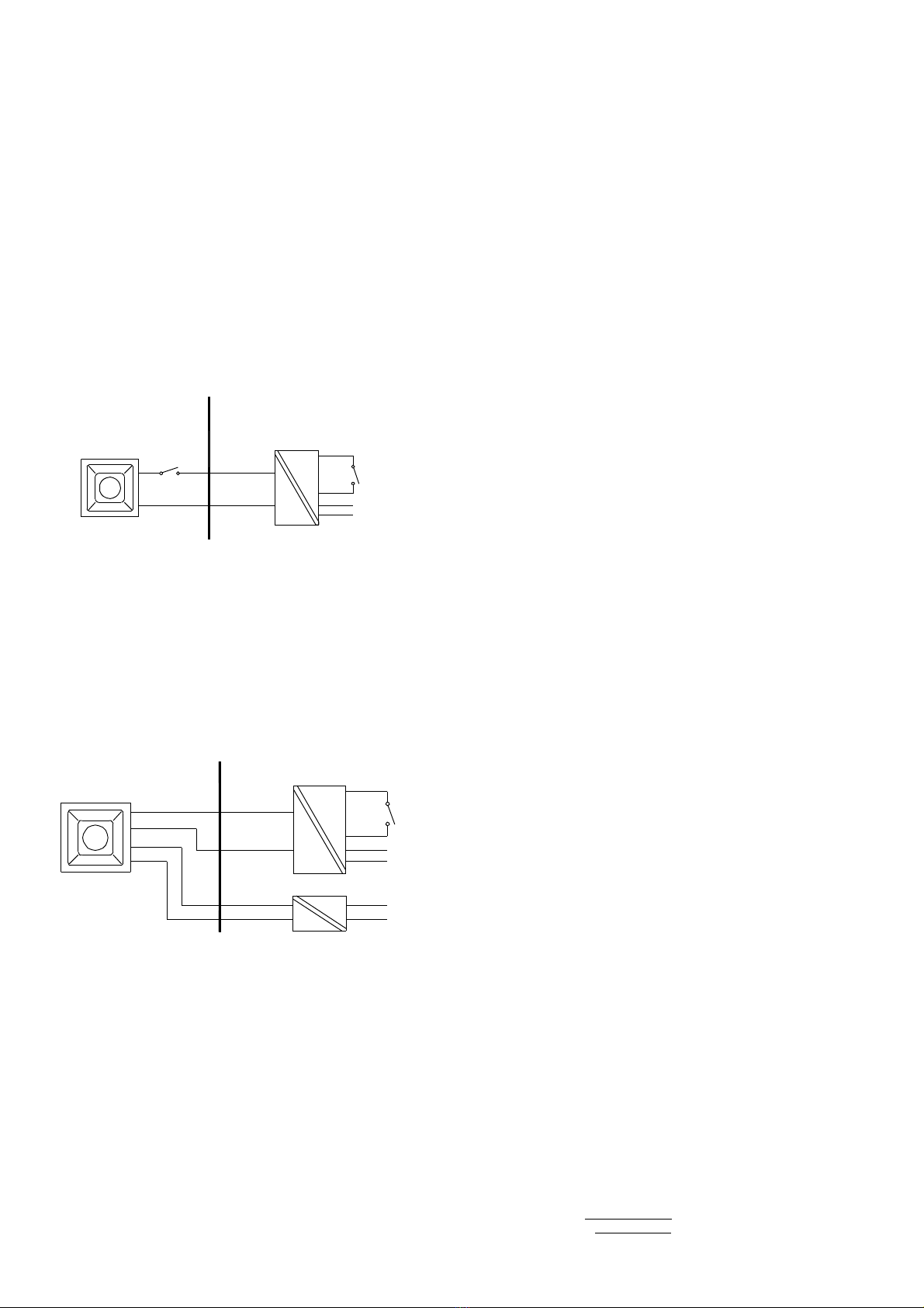
4.4TerminalsS2and S3
WhenterminalsS2orS3areconnectedto0V(- terminal)the
sounderoutputtonechangestothesecondorthirdstage
alarmrespectively.Theinputsafetyparametersforthese
terminalsare:
Ui = 28V
Ii = 0mA
Becausethepermitted inputcurrentiszero,theseterminals
mayonlybe connected toadiodereturnbarrier,an

_______________________________________________________________________________________________________________________________
EuropeanSafetySystemsLtd. Impress House, MansellRoad, Acton, London W37QHsales@e2s.com Tel: +44 (0)20 8743 8880
www.e2s.com Fax: +44 (0)20 8740 4200
DocumentNo. IS4501 Issue E27-11-09 Sheet 3of6
intrinsicallysaferelayoragalvanicisolator,all of whichmust
havebeencertifiedbyan ECNotified Body.Onlydiode
returnbarrierswithavoltage dropoflessthan 0.9Vmaybe
used.Alternatively,theseterminalsmaybeconnected
directlytoamechanicallyactivated switchwithinthe
hazardousarea.
++-- S2S3 123456
InputTerminals Volume
Control Tone Setting
Switches1-6
ON
Fig2Locationoffieldterminalsandcontrols.
4.5Otherintrinsicsafetycertifications
PleasecontactEuropean SafetySystemsLtd.fordetailsof
non-European intrinsicsafetyapprovals.
5) Installation
IS-A105Nsoundersshouldonlybeinstalled bytrained
competent personnel.
5.1Mounting
TheIS-A105Nsoundermaybe securedtoanyflatsurface
usingthetwo7mm diameterfixingholes.Theenclosure
providesIP66protectionandissuitableforinstallationin
exteriorlocationsprovidingitispositionedsothatwatercan
not collect inthehorn, andthecableentryissealed.
5.2Installationprocedure
a.SecuretheIS-A105Nsoundertoaflatsurfaceviathe
two7mm diafixingholesinthemountingfeet.
b.Removethefrontofthe sounderbyunscrewingthe
fourcaptive‘A’screwsandpullingthefrontawayfrom
theenclosure.
c.Fita20mmcableglandorconduitentryintothe
untappedholeintheenclosureandconnectthefield
wiringtotheappropriatesounderterminalsasshown
insection6andfig2ofthismanual.Thepowersupply
terminals+and-areduplicatedsothatsoundersmay
be connected inparallel,oran endoflinemonitoring
resistormaybe fitted.
d.Selecttherequired outputtonebypositioningthesix
switchesasshowninTable1andFig2.
e. Applypowertothesounderandadjustthe internal
volumecontroltoprovide therequiredsoundlevel.
f. Replacethefrontof thesounderandtightenthefour
‘A’screws.
6) ElectricalSystem Design ForInstallation In
HazardousAreasUsing ZenerBarriers
6.1Singlestagealarm
Ifthecontrolswitchisinthepositivesupply,orthepower
supplyisbeingturned onandoff, onlyasinglechannelZener
barrierisrequiredasshowninFig3.Thiscircuitmayalsobe
used ifthesounderisbeing controlled byamechanically
activated switchonthehazardousareaside ofthebarrier.
Power
Supply
+
0V
Barrier
On/Off
IS-A105N
Sounder
+
-
28V93mA
Positive
HazardousArea SafeArea
Fig3Singlestagealarmusingsinglechannelbarrier.
Ifthecontrolswitchmust be inthenegativesupply, thecircuit
showninFig4maybe used. Anydiodereturnbarriercertified
ExiabyaECNotifiedBodymaybeused,providing its
voltage dropisless than 0.9V.
Power
Supply
+
0V
Barrier
IS-A105N
Sounder
+
-
28V93mA
Positive
HazardousArea SafeArea
Diode Return
Barrier On/Off
Fig4Singlestagealarmusingtwochannelbarrier.
6.2Multi-stagealarm
ConnectingterminalS2to0Vactivatesthesecondstage
alarm,andsimilarlyterminalS3forthethirdstage alarm.Fig
5showshowthediode returnbarriersmaybe used.Ifonly
twostagesofalarmarerequired thethirdstage barrier
shouldbeomitted, the28V93mAbarrierandthesinglediode
returnchannelmaythenbe contained inonepackage.
Power
Supply
+
0V
Barrier
IS-A105N
Sounder
+
-
28V93mA
Positive
HazardousArea SafeArea
Diode Return
Barrier 2ndStage
On/Off
Diode Return
Barrier 3rd Stage
S2
S3
Fig5Multistage alarmusingZenerbarriers.

_______________________________________________________________________________________________________________________________
EuropeanSafetySystemsLtd. Impress House, MansellRoad, Acton, London W37QHsales@e2s.com Tel: +44 (0)20 8743 8880
www.e2s.com Fax: +44 (0)20 8740 4200
DocumentNo. IS4501 Issue E27-11-09 Sheet 4of6
Tone
Number
ToneDescription
Switch
Settings
123456
Second
Stage
Alarm
Third
Stage
alarm
Tone 1
Tone 2
Tone 3
Tone 4
Tone 5
Tone 6
Tone 7
Tone 8
Tone 9
Tone 10
Tone 11
Tone 12
Tone 13
Tone 14
Tone 15
Tone 16
Tone 17
Tone 18
Tone 19
Tone 20
Tone 21
Tone 22
Tone 23
Tone 24
Tone 25
Tone 26
Tone 27
Tone 28
Tone 29
Tone 30
Tone 31
Tone 32
Tone 33
Tone 34
Tone 35
Tone 36
Tone 37
Tone 38
Tone 39
Tone 40
Tone 41
Tone 42
Tone 43
Tone 44
Tone 45
Tone 46
Tone 47
Tone 48
Tone 49
Continuous340Hz
Alternating 800/1000Hz@0.25sintervals
Slowwhoop 500/1200Hz@0.3Hzwith0.5sgap repeated
Sweeping 500/1000Hz@1Hz
Continuous2400Hz
Sweeping 2400/2900Hz@7Hz
Sweeping 2400/2900Hz@1Hz
Siren 500/1200/500Hz@0.3Hz
Sawtooth1200/500Hz@1Hz- D.I.N.
Alternating 2400/2900Hz@2Hz
Intermittent1000Hz@1Hz
Alternating 800/1000Hz@0.875Hz
Intermittent2400Hz@1Hz
Intermittent800Hz0.25sON, 1sOFF
Continuous800Hz
Intermittent660Hz150NsON, 150msOFF
Alternating 544Hz(100ms)/ 440Hz(400ms)– NFS32-001
Intermittent660Hz1.8sON, 1.8sOFF
Sweep 1400Hzto1600Hzup1s1600Hzto1400Hzdown0.5s
Continuous660Hz
Alternating 554/440Hz@1Hz
Intermittent544Hz@0.875Hz
Intermittent800Hz@2Hz
Sweeping 800/1000Hz@50Hz
Sweeping 2400/2900Hz@50Hz
Simulated bell
Continuous554Hz
Continuous440Hz
Sweeping 800/1000Hz@7Hz
Continuous300Hz
Sweeping 660/1200@1Hz
TwoTone Chime
Intermittent745Hz
Alternating1000/2000Hz@0.5s– Singapore
420Hz@0.625s- Australian Alert
500-1200Hz3.75s/ 0.25s- Australian Evacuate
Continuous1000Hz
Continuous2000Hz
Intermittent800Hz0.25sON1sOFF
Alternating544Hz(100ms)/ 440Hz(400ms)– NFS32-001
MotorSiren –Slowriseto1200Hz
MotorSiren –Slowriseto800Hz
Continuous1200Hz
MotorSiren –Slowriseto2400Hz
Intermittent1000Hz1sON, 1sOFF
Sawtooth1200/500Hz@1Hz- D.I.N. (PFEERP.T.A.P)
Intermittent1000Hz1sON, 1sOFF – PFEERGeneralAlarm
420Hz@0.625s- Australian Alert
500-1200Hz3.75s/ 0.25s- Australian Evacuate
000000
100000
010000
110000
001000
101000
011000
111000
000100
100100
010100
110100
001100
101100
011100
111100
000010
100010
010010
110010
001010
101010
011010
111010
000110
100110
010110
110110
001110
101110
011110
111110
000001
100001
010001
110001
001001
101001
011001
111001
000101
100101
010101
110101
001101
101101
011101
111101
000011
Tone 2
Tone 17
Tone 2
Tone 6
Tone 3
Tone 7
Tone 10
Tone 2
Tone 15
Tone 7
Tone 2
Tone 4
Tone 15
Tone 4
Tone 2
Tone 18
Tone 2
Tone 2
Tone 2
Tone 2
Tone 2
Tone 2
Tone 6
Tone 29
Tone 29
Tone 2
Tone 26
Tone 2
Tone 7
Tone 2
Tone 26
Tone 26
Tone 2
Tone 38
Tone 36
Tone 35
Tone 9
Tone 34
Tone 23
Tone 31
Tone 2
Tone 2
Tone 2
Tone 2
Tone 38
Tone 47
Tone 46
Tone 49
Tone 26
Tone 5
Tone 5
Tone 5
Tone 5
Tone 20
Tone 5
Tone 5
Tone 5
Tone 2
Tone 5
Tone 5
Tone 5
Tone 5
Tone 5
Tone 5
Tone 5
Tone 27
Tone 5
Tone 5
Tone 5
Tone 5
Tone 5
Tone 5
Tone 5
Tone 5
Tone 15
Tone 5
Tone 5
Tone 5
Tone 5
Tone 5
Tone 15
Tone 5
Tone 45
Tone 5
Tone 5
Tone 45
Tone 45
Tone 17
Tone 27
Tone 5
Tone 5
Tone 5
Tone 5
Tone 34
Tone 37
Tone 37
Tone 5
Tone 37
ToneSelection
–Toselecttherequiredfirststagetonesetthetoneswitches1to6(see
Fig2)tothetonesetting showninthetablebelow. Thetablealsoshowswhich2nd and 3rd
stagetonesareavailableforusewiththeselectedfirststagetoneif morethanonetone
output stageisrequired.

_______________________________________________________________________________________________________________________________
EuropeanSafetySystemsLtd. Impress House, MansellRoad, Acton, London W37QHsales@e2s.com Tel: +44 (0)20 8743 8880
www.e2s.com Fax: +44 (0)20 8740 4200
DocumentNo. IS4501 Issue E27-11-09 Sheet 5of6
7) ElectricalSystem Design ForInstallation In
HazardousAreasUsing GalvanicIsolators
Galvanicisolatorsalthoughmoreexpensivethan Zener
barriers,donotrequireahighintegrityearthconnection.For
small systemswhereahighintegrityearthisnotalready
available,theuseofgalvanicisolatorsoftenreducesthe
overall installationcost andsimplifiesdesign.
7.1Singlestagealarm
TheIS-A105Nsoundermaybe powered byanygalvanic
isolatorhavingoutput parameterswithinthelimitsspecified in
section4.3,whichhasbeencertified ExiabyanECNotified
Body. Thesoundermaybe controlledbyturningthegalvanic
isolatoronandoff,orbyamechanicallyactivated switchon
thehazardousareaside oftheisolator.
+
IS-A105N
Sounder
+
-
HazardousArea SafeArea
-Power
Galvanic
Isolator
Fig6Singlestagealarmusinggalvanicisolator.
7.2Multi stagealarm
TheIS-A105Nsoundersecondandthirdstagesmaybe
activated byusingGalvanicallyIsolated Relaysthathave
outputparameterswithinthelimitsspecifiedinsection4.4.
whichhavebeencertifiedExiabyanECNotifiedBody.
SafeArea
HazardousArea
-
S2
IS-A105N
Sounder +
-
GalvanicIsolatedRelay
-
GalvanicIsolator
+
Power
Power
Fig7Multistage alarmusinggalvanicisolated relays
8) CableParameters
Themaximumpermittedcableparametersareasspecified
onthecertificateof theZenerbarrierorgalvanicisolatorthat
hasbeenselected fortheinstallation. Normallythelimitsare
notrestrictive,butcareshouldbe takennottoexceeda
capacitivelimit of83nFforinstallationswhenverylongcables
areused.
9) Volume Control
TheoutputleveloftheIS-A105Nsoundercan be setby
adjustingthevolumecontrolpotentiometer(seeFig2).
10) Servicing
Noattemptshouldbe madetorepairafaultyIS-A105N
sounder.Suspectsoundersshouldbereturned toEuropean
SafetySystemsLtd.forrepair.
11) Guarantee
Soundersthatfail withintheguarantee periodshouldbe
returned toEuropean safetySystemsLtd.Itishelpfulifa
briefdescriptionofthefault symptomsisprovided.
12) CustomerComments
European SafetySystemsLtd.isalwayspleasedtoreceive
commentsfromcustomersaboutourproductsandservices.
All communicationsareacknowledgedandwhenever
possible, suggestionsareimplemented.

_______________________________________________________________________________________________________________________________
EuropeanSafetySystemsLtd. Impress House, MansellRoad, Acton, London W37QHsales@e2s.com Tel: +44 (0)20 8743 8880
www.e2s.com Fax: +44 (0)20 8740 4200
DocumentNo. IS4501 Issue E27-11-09 Sheet 6of6
TheIS-A105NSounderhasalsobeenapprovedtotheIECEx
scheme.
TheinstallationrequirementsforIS-A105Nsounders
approvedtotheIECExschemearethesameasthe
installationrequirementsforIS-A105Nsoundersapprovedto
theATEXdirective.
CertificateNo. IECExSIR04.0038X
Marking:ExiaIICT4Ga(Ta=-40ºCto+60ºC)
Standards: IEC60079-0:2004 Edition 4
IEC60079-11:2006 Edition 5
IEC60079-26:2006 Edition 2
CONDITIONSOFCERTIFICATION(as statedon theIECEx
CertificateofConformityIECExSIR04.0038X)
1. Theequipmentshall onlybesuppliedviaTerminals
+w.r.t.Terminals-fromacertifiedbarrierhavinga
maximumopencircuit voltage Uothatisless than or
equalto28 Vandamaximumshort circuit current Io
thatisless than orequalto93mA,whereIois
resistivelylimited.
2. Thetotalcapacitanceconnectedtoterminals+wrt–
(i.e.thecapacitanceofthecableplusanyother
capacitance)shall not exceed83nF.
3. Theequipmenthasan ingressprotectionratingof
IP66;however,ifithasbeensuppliedwithouta
cableentrydevice,thentheusershall ensurethat
thedevicethatisfitted will providean ingress
protectionthatisappropriatetotheenvironmentin
whichit isinstalled i.e. IP20orbetter.
4. Theenclosureisnon-conductingandmaygenerate
an ignition-capablelevelofelectrosaticcharges
undercertainextremeconditions.The usershould
ensurethattheequipmentisnotinstalled ina
locationwhereitmaybe subjectedtoexternal
conditionsthatmightcauseabuild-upof
electrostaticchargesonnon-conductingsurfaces,
additionally,cleaningoftheequipmentshouldbe
doneonlywithadampcloth.
TheIS-A105NSounderhasalsobeenFMListed.
Marking:ISClassI, Zone0, AExiaIICT4
ISClassI, Division1, GroupsA, B, C, D
SeetheControlDrawingsD4528Sheets1and2for
installationdetailsandentityparameters.
TheIS-A105Nsoundersaremarked withthecertification
requirementsfortheATEX, IECExandFMapprovals.
e2S european safetysystemsltd.
SIRA04ATEX2301X
0518
IS-A105NSounder
LondonW37QHUK
www.e2s.com
Year/ SerialNo.
09/ 1S000001
WARNINGS:
IECEx SIR04.0038X
Term. +w.r.t. Term.-Ui=28VIi=93mA
Pi=660mWCi=0Li=0
Term. S2&S3w.r.t. Term. -Ui=28VIi=0mA
FM
APPROVED
Toavoidapossible electrostatic
charge onlyclean withadampcloth
Topreventignitionof flammable orcombustible
atmospheres,disconnectpowerbeforeservicing
Substitutionofcomponentsmayimpairsafety
ISClass I,Zone0, AExiaIICT4
ISClass l,Division 1,GroupsA,B, C,D
II 1GEx iaIICT4Ga(-40ºC<=Ta<=+60°C)
Control Drawing No. D4528
IECExCertification
FMApproval


Table of contents
Other E2S Marine Equipment manuals

E2S
E2S STExC1 User manual

E2S
E2S AlertAlight AL105N Series User manual

E2S
E2S STExC1 User manual

E2S
E2S A100 AlertAlarm User manual

E2S
E2S IS-mA1M User manual

E2S
E2S GNExS2FDC024-S User manual

E2S
E2S A105N APPELLO DC User manual

E2S
E2S Sontel BExTS110DAC115 User manual

E2S
E2S E2xS1RDC024 Manual

E2S
E2S DL112H User manual

E2S
E2S D1xS1 Series User manual

E2S
E2S BE DCS110-L1D Series User manual

E2S
E2S D1xS2FDC024-D User manual

E2S
E2S AL121H Series User manual

E2S
E2S BE*H120D User manual

E2S
E2S GNExS2F User manual

E2S
E2S BExCTS110-05D-P User manual

E2S
E2S BExDCTS110-05D User manual

E2S
E2S D105 AlertAlarm User manual

E2S
E2S STExS1 User manual